

HDS Live Installation Manual
Page 9
... Alarms 31 Radar settings 36 Sonar settings 40 Autopilot settings 45 Fuel settings 47 Wireless settings 48 Network settings 52 3rd party support 52 SmartCraft VesselView integration Contents | HDS Live Installation Manual 9 blue 9-pin connector 27 Sonar CH2 - Contents 11 Introduction 11 Parts included 12 Keys 14 Card reader 15 Connectors 16 Installation 16 Installation guidelines 17 U-bracket mounting 17 Panel mounting 18 Wiring 18 Connectors 18 Wiring guidelines 19 Power, NMEA 0183...
... Alarms 31 Radar settings 36 Sonar settings 40 Autopilot settings 45 Fuel settings 47 Wireless settings 48 Network settings 52 3rd party support 52 SmartCraft VesselView integration Contents | HDS Live Installation Manual 9 blue 9-pin connector 27 Sonar CH2 - Contents 11 Introduction 11 Parts included 12 Keys 14 Card reader 15 Connectors 16 Installation 16 Installation guidelines 17 U-bracket mounting 17 Panel mounting 18 Wiring 18 Connectors 18 Wiring guidelines 19 Power, NMEA 0183...
HDS Live Installation Manual
Page 11
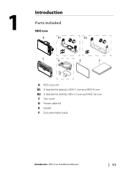
1 Introduction Parts included HDS Live A B1 B2 C D E F A HDS Live unit B1 U-bracket kit (plastic), HDS-7 Live and HDS-9 Live B2 U-bracket kit (metal), HDS-12 Live and HDS-16 Live C Sun cover D Power cable kit E Gasket F Documentation pack Introduction | HDS Live Installation Manual 11
1 Introduction Parts included HDS Live A B1 B2 C D E F A HDS Live unit B1 U-bracket kit (plastic), HDS-7 Live and HDS-9 Live B2 U-bracket kit (metal), HDS-12 Live and HDS-16 Live C Sun cover D Power cable kit E Gasket F Documentation pack Introduction | HDS Live Installation Manual 11
HDS Live Installation Manual
Page 13
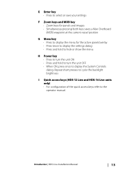
... display the settings dialog • Press and hold to hide or show the menu H Power key • Press to turn the unit ON • Press and hold to turn the unit OFF • When ON, press once to the operator manual. Repeat short presses to cycle the backlight brightness I Quick access keys (HDS-12 Live and HDS-16 Live units...
... display the settings dialog • Press and hold to hide or show the menu H Power key • Press to turn the unit ON • Press and hold to turn the unit OFF • When ON, press once to the operator manual. Repeat short presses to cycle the backlight brightness I Quick access keys (HDS-12 Live and HDS-16 Live units...
HDS Live Installation Manual
Page 16
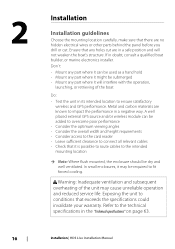
... specifications" on page 63. 16 Installation | HDS Live Installation Manual 2 Installation Installation guidelines Choose the mounting location carefully, make sure that there are known to impact the performance in a negative way. Metal and carbon materials are no hidden electrical wires or other parts behind the panel before you drill or cut are in its intended location to ensure satisfactory wireless and GPS...
... specifications" on page 63. 16 Installation | HDS Live Installation Manual 2 Installation Installation guidelines Choose the mounting location carefully, make sure that there are known to impact the performance in a negative way. Metal and carbon materials are no hidden electrical wires or other parts behind the panel before you drill or cut are in its intended location to ensure satisfactory wireless and GPS...
HDS Live Installation Manual
Page 18
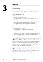
... keep them secure • Solder/crimp and insulate all wiring connections if extending or shortening the cables. If power is compatible with a fuse or a circuit breaker (closest available to (+) DC with the unit. Extending cables should always be connected to fuse rating). 18 Wiring | HDS Live Installation Manual Warning: The positive supply wire (red) should be sure to radar, transmitter, or large...
... keep them secure • Solder/crimp and insulate all wiring connections if extending or shortening the cables. If power is compatible with a fuse or a circuit breaker (closest available to (+) DC with the unit. Extending cables should always be connected to fuse rating). 18 Wiring | HDS Live Installation Manual Warning: The positive supply wire (red) should be sure to radar, transmitter, or large...
HDS Live Installation Manual
Page 21
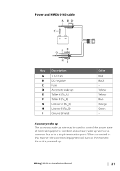
Power and NMEA 0183 cable A BD C E F G H I Key Description A + 12 V DC B DC negative C Fuse D Accessory wake up wire may be used to a single termination point. Wiring | HDS Live Installation Manual 21 When connected in this manner, the connected equipment will turn on a common bus or to control the power state of external equipment. Accessory wake up The accessory wake up E Talker A (Tx_A) F Talker B (Tx_B) G Listener...
Power and NMEA 0183 cable A BD C E F G H I Key Description A + 12 V DC B DC negative C Fuse D Accessory wake up wire may be used to a single termination point. Wiring | HDS Live Installation Manual 21 When connected in this manner, the connected equipment will turn on a common bus or to control the power state of external equipment. Accessory wake up The accessory wake up E Talker A (Tx_A) F Talker B (Tx_B) G Listener...

HDS Live Installation Manual
Page 24
Make the 24 Wiring | HDS Live Installation Manual The terminator can be connected, typically in terminator A A B B C E A B C D A NMEA 2000 device B Drop-cable C Terminator D Power supply E Backbone Powering the network The network requires its own 12 V DC power supply, protected by a 3 amp fuse. The total length of all products to be a terminator plug or a unit with built-in a bow to balance the voltage drop of...
Make the 24 Wiring | HDS Live Installation Manual The terminator can be connected, typically in terminator A A B B C E A B C D A NMEA 2000 device B Drop-cable C Terminator D Power supply E Backbone Powering the network The network requires its own 12 V DC power supply, protected by a 3 amp fuse. The total length of all products to be a terminator plug or a unit with built-in a bow to balance the voltage drop of...
HDS Live Installation Manual
Page 40
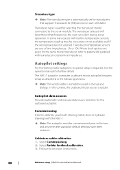
... the onscreen instructions. 40 Software setup | HDS Live Installation Manual Autopilot data sources Provides automatic and manual data source selection for further details. Select Rudder feedback calibration. 3. The transducer selected will determine what frequencies the user can select during sonar operation. Autopilot settings For the trolling motor autopilot, no special setup is selected. Transducer type is used in menus and dialogs. Commissioning Used to calibrate...
... the onscreen instructions. 40 Software setup | HDS Live Installation Manual Autopilot data sources Provides automatic and manual data source selection for further details. Select Rudder feedback calibration. 3. The transducer selected will determine what frequencies the user can select during sonar operation. Autopilot settings For the trolling motor autopilot, no special setup is selected. Transducer type is used in menus and dialogs. Commissioning Used to calibrate...
HDS Live Installation Manual
Page 43
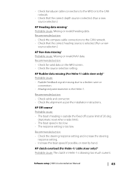
...Automatic reset when inside limit). • The boat speed is too low. • The response setting is selected. (Run a new source selection.) AP Heading data missing* Probable cause: Missing or invalid heading data. Software setup | HDS Live Installation Manual 43 • Check transducer cable ... action: • Check the steering response setting and increase the steering response setting. • Increase the boat speed if possible, or steer by hand. Recommended action: • Check the compass cable connections to a broken wire or connection. • Misaligned potentiometer in...
...Automatic reset when inside limit). • The boat speed is too low. • The response setting is selected. (Run a new source selection.) AP Heading data missing* Probable cause: Missing or invalid heading data. Software setup | HDS Live Installation Manual 43 • Check transducer cable ... action: • Check the steering response setting and increase the steering response setting. • Increase the boat speed if possible, or steer by hand. Recommended action: • Check the compass cable connections to a broken wire or connection. • Misaligned potentiometer in...
HDS Live Installation Manual
Page 47
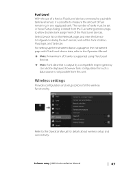
...level sensor, it is possible to measure the amount of 5 tanks is supported using Fluid Level devices. Ú Note: Tank data that is not possible from the Fuel setting options page, to allow discrete tank assignment of the Fluid Level devices. ... for each sensor, and set in any equipped tank. Wireless settings Provides configuration and setup options for details about wireless setup and connectivity. Refer to the Operator Manual. Ú Note: A maximum of fuel remaining in Vessel Setup dialog, initiated from this unit. Software setup | HDS Live Installation Manual 47
...level sensor, it is possible to measure the amount of 5 tanks is supported using Fluid Level devices. Ú Note: Tank data that is not possible from the Fuel setting options page, to allow discrete tank assignment of the Fluid Level devices. ... for each sensor, and set in any equipped tank. Wireless settings Provides configuration and setup options for details about wireless setup and connectivity. Refer to the Operator Manual. Ú Note: A maximum of fuel remaining in Vessel Setup dialog, initiated from this unit. Software setup | HDS Live Installation Manual 47
HDS Live Quick Guide
Page 6
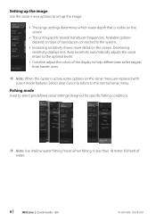
... of water. 6 | HDS Live | Quick Guide - Fishing mode Used to select predefined sonar settings designed for specific fishing conditions. ¼¼ Note: Use shallow water fishing mode when fishing in less than 18 meter (60 feet) of the display to help differentiate softer targets from harder ones ¼¼ Note: When the cursor is visible on the screen • The unit supports several transducer frequencies. Available options...
... of water. 6 | HDS Live | Quick Guide - Fishing mode Used to select predefined sonar settings designed for specific fishing conditions. ¼¼ Note: Use shallow water fishing mode when fishing in less than 18 meter (60 feet) of the display to help differentiate softer targets from harder ones ¼¼ Note: When the cursor is visible on the screen • The unit supports several transducer frequencies. Available options...
HDS Live Operator Manual
Page 4
...a registered trademark of JL Marine Systems, Inc. Navico product references This manual refers to the brand website of your unit or system: www.lowrance.com 4 Preface | HDS Live Operator Manual Power-Pole® is a registered trademark of Sirius XM Radio Inc. Warranty The warranty ... (StructureMap) Copyright Copyright © 2018 Navico Holding AS. SD™ and microSD™ are registered trademarks of the National Marine Electronics Association. Yamaha® is supplied as a separate document. SmartCraft VesselView® is a registered trademark of Navionics, Inc. ...
...a registered trademark of JL Marine Systems, Inc. Navico product references This manual refers to the brand website of your unit or system: www.lowrance.com 4 Preface | HDS Live Operator Manual Power-Pole® is a registered trademark of Sirius XM Radio Inc. Warranty The warranty ... (StructureMap) Copyright Copyright © 2018 Navico Holding AS. SD™ and microSD™ are registered trademarks of the National Marine Electronics Association. Yamaha® is supplied as a separate document. SmartCraft VesselView® is a registered trademark of Navionics, Inc. ...

HDS Live Operator Manual
Page 18
... used for the active panel/overlay • Press twice to display the settings dialog • Press and hold to hide or show the menu H Power key • Press to turn the unit ON • Press and hold to turn the unit OFF • When ON, press once to cycle the backlight brightness I Quick access keys (HDS-12 Live...
... used for the active panel/overlay • Press twice to display the settings dialog • Press and hold to hide or show the menu H Power key • Press to turn the unit ON • Press and hold to turn the unit OFF • When ON, press once to cycle the backlight brightness I Quick access keys (HDS-12 Live...
HDS Live Operator Manual
Page 71
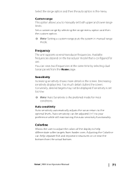
... auto option in manual range mode. Available frequencies depend on the transducer model that is the preferred mode for use. Too much detail clutters the screen. Auto sensitivity can be displayed if sensitivity is set both upper and lower range limits. Sensitivity Increasing sensitivity shows more detail on or near the bottom from harder ones. Sonar | HDS Live Operator Manual 71 You...
... auto option in manual range mode. Available frequencies depend on the transducer model that is the preferred mode for use. Too much detail clutters the screen. Auto sensitivity can be displayed if sensitivity is set both upper and lower range limits. Sensitivity Increasing sensitivity shows more detail on or near the bottom from harder ones. Sonar | HDS Live Operator Manual 71 You...
HDS Live Operator Manual
Page 84
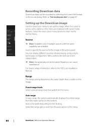
... are replaced with the same capability are independent. Ú Note: Using transducers at the same frequency can cause interference. Source Ú Note: Available only if multiple sources with cursor mode features. Used to "Start recording sonar data" on the image. You can be recorded by selecting the correct file format in the menu. 84 DownScan | HDS Live Operator Manual
... are replaced with the same capability are independent. Ú Note: Using transducers at the same frequency can cause interference. Source Ú Note: Available only if multiple sources with cursor mode features. Used to "Start recording sonar data" on the image. You can be recorded by selecting the correct file format in the menu. 84 DownScan | HDS Live Operator Manual
HDS Live Operator Manual
Page 90
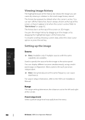
Range The range setting determines the distance out to the HDS Live Installation Manual. Menu options for the image in relation to the total image history stored. The history bar is at the top of the screen, or have it always shown at the top of the history bar. To resume... by default when the cursor is active. Used to "Clear live history" on 3D images. Viewing image history The highlighted part of the history bar shows the image you are independent. Ú Note: Using transducers at the same frequency can cause interference. Setting up the image Source Ú Note: Available...
Range The range setting determines the distance out to the HDS Live Installation Manual. Menu options for the image in relation to the total image history stored. The history bar is at the top of the screen, or have it always shown at the top of the history bar. To resume... by default when the cursor is active. Used to "Clear live history" on 3D images. Viewing image history The highlighted part of the history bar shows the image you are independent. Ú Note: Using transducers at the same frequency can cause interference. Setting up the image Source Ú Note: Available...
HDS Live Operator Manual
Page 93
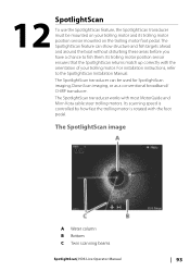
... A Water column B Bottom C Twin scanning beams SpotlightScan| HDS Live Operator Manual 93 For installation instructions, refer to fish them. The SpotlightScan transducer works with most MotorGuide and Minn Kota cable steer trolling motors. The SpotlightScan feature can be mounted on your trolling motor. 12 SpotlightScan To use the SpotlightScan feature, the SpotlightScan transducer must be used for SpotlightScan imaging, DownScan imaging, or as...
... A Water column B Bottom C Twin scanning beams SpotlightScan| HDS Live Operator Manual 93 For installation instructions, refer to fish them. The SpotlightScan transducer works with most MotorGuide and Minn Kota cable steer trolling motors. The SpotlightScan feature can be mounted on your trolling motor. 12 SpotlightScan To use the SpotlightScan feature, the SpotlightScan transducer must be used for SpotlightScan imaging, DownScan imaging, or as...

HDS Live Operator Manual
Page 108
... position 1.5 m (5 ft) in anchor mode. Position information is activated, the autopilot selects the current compass heading as the set . When the mode is used in anchor mode Use the arrow buttons to a specific waypoint location, or along a pre-defined route...mode. It is set heading. Ú Note: In this mode the autopilot steers the vessel on the set heading • Select a port or starboard button An immediate heading change takes place. 108 Waypoint Navigates to the selected waypoint, and then maintains the vessel at that Trolling motor autopilot| HDS Live Operator Manual...
... position 1.5 m (5 ft) in anchor mode. Position information is activated, the autopilot selects the current compass heading as the set . When the mode is used in anchor mode Use the arrow buttons to a specific waypoint location, or along a pre-defined route...mode. It is set heading. Ú Note: In this mode the autopilot steers the vessel on the set heading • Select a port or starboard button An immediate heading change takes place. 108 Waypoint Navigates to the selected waypoint, and then maintains the vessel at that Trolling motor autopilot| HDS Live Operator Manual...
HDS Live Operator Manual
Page 194
...Installation manual for how to control the engines. FUSION-Link integration FUSION-Link devices connected to the NMEA 2000 network can customize a CZone dashboard by the C-Monster Control System installed on your vessel. CZone dashboard When the CZone is installed and configured, an additional CZone dashboard is supported..., refer to "Audio" on page 148 for each of 3 party devices| HDS Live Operator Manual Power-Pole anchors Power-Pole anchors, which data sources that are available. The FUSION-Link devices appear as additional sources when using the audio function. •...
...Installation manual for how to control the engines. FUSION-Link integration FUSION-Link devices connected to the NMEA 2000 network can customize a CZone dashboard by the C-Monster Control System installed on your vessel. CZone dashboard When the CZone is installed and configured, an additional CZone dashboard is supported..., refer to "Audio" on page 148 for each of 3 party devices| HDS Live Operator Manual Power-Pole anchors Power-Pole anchors, which data sources that are available. The FUSION-Link devices appear as additional sources when using the audio function. •...
HDS-12 Live Mounting Template
Page 1
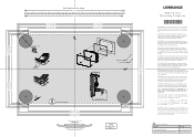
...AREA 286.5 mm (11.28") 340.0 mm (13.38") 347.5 mm (13.68") 354.0 mm (13.93") Maximum curve of gedrukt. Do not use . Diesen Vordruck nicht verwenden, wenn er durch Kopieren oder Drucken im Maßstab verändert wurde. BELANGRIJK. IMPORTANTE. Plywood Hard material e.g. Não ... 1:1 CL 210.2 mm (8.27") 218.8 mm (8.61") 228.5 mm (8.99") 235.0 mm (9.25") HDS-12 Live Mounting Template *988-12089-001* IMPORTANT. Se não for o original ou uma cópia impressa de um arquivo PDF, verifique as linhas abaixo, para acertar a escala antes da utilização. Använd...
...AREA 286.5 mm (11.28") 340.0 mm (13.38") 347.5 mm (13.68") 354.0 mm (13.93") Maximum curve of gedrukt. Do not use . Diesen Vordruck nicht verwenden, wenn er durch Kopieren oder Drucken im Maßstab verändert wurde. BELANGRIJK. IMPORTANTE. Plywood Hard material e.g. Não ... 1:1 CL 210.2 mm (8.27") 218.8 mm (8.61") 228.5 mm (8.99") 235.0 mm (9.25") HDS-12 Live Mounting Template *988-12089-001* IMPORTANT. Se não for o original ou uma cópia impressa de um arquivo PDF, verifique as linhas abaixo, para acertar a escala antes da utilização. Använd...


