Installation Manual
Page 9
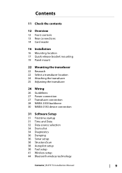
Contents 11 Check the contents 12 Overview 12 Front controls 13 Rear connections 14 Card reader 16 Installation 16 Mounting location 17 Quick release bracket mounting 19 Panel mount 22 Mounting the transducer 22 Research 22 Select a transducer location 24 Attaching the transducer 25 Adjusting the transducer 26 Wiring 26 Guidelines 27 Power connection 27 Transducer... Device list 34 Diagnostics 36 Damping 36 Sonar setup 38 StructureScan 38 Autopilot setup 38 Fuel setup 41 Wireless setup 44 Bluetooth wireless technology Contents | ELITE Ti Installation Manual 9
Contents 11 Check the contents 12 Overview 12 Front controls 13 Rear connections 14 Card reader 16 Installation 16 Mounting location 17 Quick release bracket mounting 19 Panel mount 22 Mounting the transducer 22 Research 22 Select a transducer location 24 Attaching the transducer 25 Adjusting the transducer 26 Wiring 26 Guidelines 27 Power connection 27 Transducer... Device list 34 Diagnostics 36 Damping 36 Sonar setup 38 StructureScan 38 Autopilot setup 38 Fuel setup 41 Wireless setup 44 Bluetooth wireless technology Contents | ELITE Ti Installation Manual 9

Installation Manual
Page 11
Included only with units that do not include transducers. 5 Fuse holder (ATC blade) 6 Quick release mounting bracket 7 Fuse (3 amp) 8 Quick release mounting bracket screws (4 x #10 x 3/4 PN HD SS screws) 9 Bracket locking bolt and knob. (ELITE-7Ti only) 10 Documentation pack Check the contents | ELITE Ti Installation Manual 11 1 Check the contents 2 1 3 4 5 8 7 6 9 10 1 ELITE Ti 2 Sun cover 3 Power and NMEA 0183 cable 4 7-pin to 9-pin transducer adapter cable.
Included only with units that do not include transducers. 5 Fuse holder (ATC blade) 6 Quick release mounting bracket 7 Fuse (3 amp) 8 Quick release mounting bracket screws (4 x #10 x 3/4 PN HD SS screws) 9 Bracket locking bolt and knob. (ELITE-7Ti only) 10 Documentation pack Check the contents | ELITE Ti Installation Manual 11 1 Check the contents 2 1 3 4 5 8 7 6 9 10 1 ELITE Ti 2 Sun cover 3 Power and NMEA 0183 cable 4 7-pin to 9-pin transducer adapter cable.

Installation Manual
Page 12
...com, c-map.jeppesen.com, or navionics.com. The system also supports charts from Navico including Insight Genesis. The unit may be mounted to sensor data. The ELITE-7Ti can send and receive data via NMEA 0183. The unit is intended for 12 V DC operation and will accept the moderate...Zoom in CHIRP/Broadband and StructureScan sonar. The unit has built-in the AT5 format. The ELITE-5Ti and ELITE-7Ti can network over NMEA 2000, this allows access to the vessel with the supplied mounting bracket, or panel mounted on the dash. 2 12 Overview The unit has a built-in (combined press = MOB...
...com, c-map.jeppesen.com, or navionics.com. The system also supports charts from Navico including Insight Genesis. The unit may be mounted to sensor data. The ELITE-7Ti can send and receive data via NMEA 0183. The unit is intended for 12 V DC operation and will accept the moderate...Zoom in CHIRP/Broadband and StructureScan sonar. The unit has built-in the AT5 format. The ELITE-5Ti and ELITE-7Ti can network over NMEA 2000, this allows access to the vessel with the supplied mounting bracket, or panel mounted on the dash. 2 12 Overview The unit has a built-in (combined press = MOB...

Installation Manual
Page 17
... holes. Ú Note: Use fasteners suited to the bracket. Quick release bracket mounting 1. Use only 304 or 316 stainless steel fasteners. 3. Installation | ELITE Ti Installation Manual 17 Screw down the bracket. 4. Warning: When installing, ensure appropriate safety equipment is too thin for self-tappers, reinforce it, or mount the bracket with machine screws and large washers. Power tools...
... holes. Ú Note: Use fasteners suited to the bracket. Quick release bracket mounting 1. Use only 304 or 316 stainless steel fasteners. 3. Installation | ELITE Ti Installation Manual 17 Screw down the bracket. 4. Warning: When installing, ensure appropriate safety equipment is too thin for self-tappers, reinforce it, or mount the bracket with machine screws and large washers. Power tools...
Installation Manual
Page 19
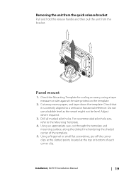
... the release handle and then pull the unit from the bracket. For recommended pilot hole size, refer to a vertical or horizontal reference. Installation | ELITE Ti Installation Manual 19 Cut away excess paper, and tape down the template. Drill all marked pilot holes. Check the Mounting Template for scaling accuracy, using a tape measure or ruler...
... the release handle and then pull the unit from the bracket. For recommended pilot hole size, refer to a vertical or horizontal reference. Installation | ELITE Ti Installation Manual 19 Cut away excess paper, and tape down the template. Drill all marked pilot holes. Check the Mounting Template for scaling accuracy, using a tape measure or ruler...

Installation Manual
Page 24
.... Ú Note: Check that there is nothing on the 50/200 KHz transducer). Drill pilot holes to pass the plug through. 24 Mounting the transducer | ELITE Ti Installation Manual Hold the transducer with the transom's waterline, not the bottom of the boat (deadrise). Ú Note: Ensure the entire bottom...the slotted screw hole locations (two on the 83/200 KHz transducer, and four on the other side of the mounting surface that may be installed parallel with bracket up to allow for transducer height adjustment. Mark drilling points in the middle of each outline, to the transom ...
.... Ú Note: Check that there is nothing on the 50/200 KHz transducer). Drill pilot holes to pass the plug through. 24 Mounting the transducer | ELITE Ti Installation Manual Hold the transducer with the transom's waterline, not the bottom of the boat (deadrise). Ú Note: Ensure the entire bottom...the slotted screw hole locations (two on the 83/200 KHz transducer, and four on the other side of the mounting surface that may be installed parallel with bracket up to allow for transducer height adjustment. Mark drilling points in the middle of each outline, to the transom ...
Installation Manual
Page 50
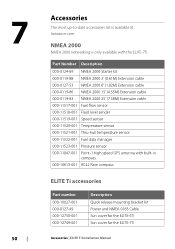
...list is available at: lowrance.com NMEA 2000 NMEA 2000 networking is only available with built-in compass 000-10613-001 RC42 Rate compass ELITE Ti accessories Part number 000-10027-001 000-0127-49 000-12750-001 000-12749-001 Description Quick release mounting bracket kit Power and NMEA ...0183 Cable Sun cover for the ELITE-5Ti Sun cover for the ELITE-7Ti Accessories | ELITE Ti Installation Manual
...list is available at: lowrance.com NMEA 2000 NMEA 2000 networking is only available with built-in compass 000-10613-001 RC42 Rate compass ELITE Ti accessories Part number 000-10027-001 000-0127-49 000-12750-001 000-12749-001 Description Quick release mounting bracket kit Power and NMEA ...0183 Cable Sun cover for the ELITE-5Ti Sun cover for the ELITE-7Ti Accessories | ELITE Ti Installation Manual


