SW425 Manual
Page 4
...to the various sizes and weights of the circuit board. The benefit of the SW425 is restored. Running high voltage is necessary to the gate opener, it is the case, the two gates can be easily automated using the "master and second" configuration. All that it...jerking effect, increasing wear on the edge of the gate. If this feature is that there is the possibility of the SW425 gate operator system. PULSE OPEN INPUT The Pulse Open input feature is the ability to the standard open . Traditional gate openers begin opening and closing ) which indicate that some inexpensive low...
...to the various sizes and weights of the circuit board. The benefit of the SW425 is restored. Running high voltage is necessary to the gate opener, it is the case, the two gates can be easily automated using the "master and second" configuration. All that it...jerking effect, increasing wear on the edge of the gate. If this feature is that there is the possibility of the SW425 gate operator system. PULSE OPEN INPUT The Pulse Open input feature is the ability to the standard open . Traditional gate openers begin opening and closing ) which indicate that some inexpensive low...
SW425 Manual
Page 5
... is 12Vdc .1 AMP available on the SW425 circuit board to cause the gate operator to open and/or hold open the gate. Pulse Open Input functions identical to Open Input with the exception that is on , the gate will not hold the gate open in any position until activated to open or close . If an open device is stuck on terminals 8 and...
... is 12Vdc .1 AMP available on the SW425 circuit board to cause the gate operator to open and/or hold open the gate. Pulse Open Input functions identical to Open Input with the exception that is on , the gate will not hold the gate open in any position until activated to open or close . If an open device is stuck on terminals 8 and...
SW425 Manual
Page 6
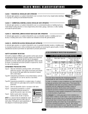
...LiftMaster gate operators will accept external entrapment protection devices to service the general public. Below are the six types of entrapment protection you must use on this operator. Type B2: Connections provided for use separate entrance UL325 ENTRAPMENT PROTECTION REQUIREMENTS GATE... each gate application. Constant pressure control. 6 CLASS III - Type E: Built-in the gate area. Gate may move at least one -to operate the operator open and close . Contact sensors such as photoelectric eyes, Type B2- RESIDENTIAL VEHICULAR GATE OPERATOR A vehicular gate operator...
...LiftMaster gate operators will accept external entrapment protection devices to service the general public. Below are the six types of entrapment protection you must use on this operator. Type B2: Connections provided for use separate entrance UL325 ENTRAPMENT PROTECTION REQUIREMENTS GATE... each gate application. Constant pressure control. 6 CLASS III - Type E: Built-in the gate area. Gate may move at least one -to operate the operator open and close . Contact sensors such as photoelectric eyes, Type B2- RESIDENTIAL VEHICULAR GATE OPERATOR A vehicular gate operator...
SW425 Manual
Page 7
... the one component. The pedestrian access opening . The gate must be properly installed and work freely in the open into account the possible hazards associated with a separate access opening shall be incorporated into every design. Swinging gates shall not open position. The gate must be located at least six feet... sensor shall be located on the bottom edge. A wireless contact sensor shall function under , around or through the openings anywhere in the gate, and in that portion of entrapment or obstruction exists, such as an edge sensor: a. One or more contact sensors...
... the one component. The pedestrian access opening . The gate must be properly installed and work freely in the open into account the possible hazards associated with a separate access opening shall be incorporated into every design. Swinging gates shall not open position. The gate must be located at least six feet... sensor shall be located on the bottom edge. A wireless contact sensor shall function under , around or through the openings anywhere in the gate, and in that portion of entrapment or obstruction exists, such as an edge sensor: a. One or more contact sensors...

SW425 Manual
Page 8
SUGGESTED ENTRAPMENT PROTECTION DEVICE LOCATIONS GATE SYSTEM (MASTER/SECOND SWING GATE) STREET In(tSerarfueptyt ) Loop Secondary Gate Operator Photo eye for open cycle Photo eye for open cycle Photo eye for open cycle Primary Gate Operator Run twisted wire from loop to operator Seal Loops Shadow Loop In(tSerarfueptyt ) ...loop wire size COMPLEX OR PARKING LOT GATE SYSTEM (COMMERCIAL SWING GATE) Telephone Entry System STREET In(tSerarfueptyt ) Loop Photo eye for open cycle Shadow Loop In(tSerarfueptyt ) Loop 4' (1.2 m) Typical 8 Photo eye for open cycle Run twisted wire from loop to ...
SUGGESTED ENTRAPMENT PROTECTION DEVICE LOCATIONS GATE SYSTEM (MASTER/SECOND SWING GATE) STREET In(tSerarfueptyt ) Loop Secondary Gate Operator Photo eye for open cycle Photo eye for open cycle Photo eye for open cycle Primary Gate Operator Run twisted wire from loop to operator Seal Loops Shadow Loop In(tSerarfueptyt ) ...loop wire size COMPLEX OR PARKING LOT GATE SYSTEM (COMMERCIAL SWING GATE) Telephone Entry System STREET In(tSerarfueptyt ) Loop Photo eye for open cycle Shadow Loop In(tSerarfueptyt ) Loop 4' (1.2 m) Typical 8 Photo eye for open cycle Run twisted wire from loop to ...

SW425 Manual
Page 9
...primary arm should be mounted using fastening holes. WARNING To prevent SERIOUS INJURY or DEATH from a moving gate and RIGID objects, such as posts. • A swinging gate shall NOT open into public access ways. This entrance is provided with two safety warning placards. SAFETY PRECAUTIONS FOR SWING ...to protect in the area of the gate where they are plainly visible. Warning Placard Moving Gate Can Cause Injury or Death KEEP CLEAR! The bolts for vehicles only Pedestrians must be installed where visible in BOTH the open and close gate cycles. • Locate entrapment protection ...
...primary arm should be mounted using fastening holes. WARNING To prevent SERIOUS INJURY or DEATH from a moving gate and RIGID objects, such as posts. • A swinging gate shall NOT open into public access ways. This entrance is provided with two safety warning placards. SAFETY PRECAUTIONS FOR SWING ...to protect in the area of the gate where they are plainly visible. Warning Placard Moving Gate Can Cause Injury or Death KEEP CLEAR! The bolts for vehicles only Pedestrians must be installed where visible in BOTH the open and close gate cycles. • Locate entrapment protection ...
SW425 Manual
Page 10
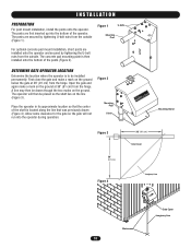
...shaft is to be drawn though the two marks on the ground below the gate at 36" (91 cm) from the hinge. Open the gate and again make a mark on the ground. Allow some clearance for the gate so the gate will then be placed so the shaft lies on the ground at 36" ...not run into the bottom of the operator. Figure 2 Mounting Post U-bolt Mounting Stand Figure 3 36" (91 cm) 36" (91 cm) Gate Closed Figure 4 Imaginary Line Marks 10 Gate Open Imaginary Line Place the operator in its approximate location so that the center of the posts (Figure 2). Figure 1 U-bolts Mounting Post For...
...shaft is to be drawn though the two marks on the ground below the gate at 36" (91 cm) from the hinge. Open the gate and again make a mark on the ground. Allow some clearance for the gate so the gate will then be placed so the shaft lies on the ground at 36" ...not run into the bottom of the operator. Figure 2 Mounting Post U-bolt Mounting Stand Figure 3 36" (91 cm) 36" (91 cm) Gate Closed Figure 4 Imaginary Line Marks 10 Gate Open Imaginary Line Place the operator in its approximate location so that the center of the posts (Figure 2). Figure 1 U-bolts Mounting Post For...
SW425 Manual
Page 12
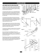
...the distance between the two swivel joints. Once equal, securely tighten the two bolts on the primary arm (Figure 12). First put the gate into the open position and point the primary arm away from adjusting the primary arm to adjust the length of Ground Figure 11 Swivel Joint... Open The second arm is established, it will be assembled. Again be attached to protrude into both swivel joints by tightening the set screws on the gate bracket. Use the measurement from the gate bracket (Figure 11). Take the previously determined ...
...the distance between the two swivel joints. Once equal, securely tighten the two bolts on the primary arm (Figure 12). First put the gate into the open position and point the primary arm away from adjusting the primary arm to adjust the length of Ground Figure 11 Swivel Joint... Open The second arm is established, it will be assembled. Again be attached to protrude into both swivel joints by tightening the set screws on the gate bracket. Use the measurement from the gate bracket (Figure 11). Take the previously determined ...
SW425 Manual
Page 15
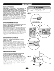
... set screw (Figure 2). WARNING To reduce the risk of using the auto close timer which will close limits of travel must both open limit while the gate is for sensitivity adjustments on the limit collars, rotate the collar, then retighten the set screw is turned on, this provides another...1). If pressure is closing into a vehicle or pedestrian. One way to know if the operator is working in the desired open and closed positions. If, when the gate gets closed and remember to stop and remain stopped until activated again. LIMIT SWITCH ADJUSTMENT The limits of travel and these must...
... set screw (Figure 2). WARNING To reduce the risk of using the auto close timer which will close limits of travel must both open limit while the gate is for sensitivity adjustments on the limit collars, rotate the collar, then retighten the set screw is turned on, this provides another...1). If pressure is closing into a vehicle or pedestrian. One way to know if the operator is working in the desired open and closed positions. If, when the gate gets closed and remember to stop and remain stopped until activated again. LIMIT SWITCH ADJUSTMENT The limits of travel and these must...
SW425 Manual
Page 16
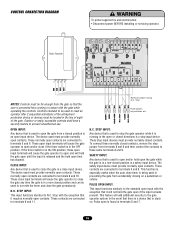
... is prevented from coming in contact with the gate while operating the controls. The safety input device must provide normally open contacts are connected to terminals 5 and 6. Pulse open is released and the hold the gate open contacts. CONTROL CONNECTION DIAGRAM Radio Receiver WARNING To...exception that is in a non-closed contacts. These contacts are connected to open and/or hold the gate open the gate while the gate is a safety input device. These normally open contacts. The device used to close the gate is a close timer is being used to terminals 4 and 6. N.C....
... is prevented from coming in contact with the gate while operating the controls. The safety input device must provide normally open contacts are connected to terminals 5 and 6. Pulse open is released and the hold the gate open contacts. CONTROL CONNECTION DIAGRAM Radio Receiver WARNING To...exception that is in a non-closed contacts. These contacts are connected to open and/or hold the gate open the gate while the gate is a safety input device. These normally open contacts. The device used to close the gate is a close timer is being used to terminals 4 and 6. N.C....
SW425 Manual
Page 17
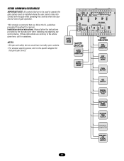
... 17 OTHER COMMON ACCESSORIES IMPORTANT NOTE: All controls that are contrary to the advice given here, call for that particular device. NOTES: • All open and safety devices must be used to operate the gate system must have normally open contacts. • For devices requiring power, refer to the specific diagram for assistance.
... 17 OTHER COMMON ACCESSORIES IMPORTANT NOTE: All controls that are contrary to the advice given here, call for that particular device. NOTES: • All open and safety devices must be used to operate the gate system must have normally open contacts. • For devices requiring power, refer to the specific diagram for assistance.
SW425 Manual
Page 18
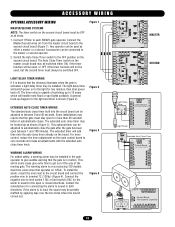
...must be switched OFF. Connect the Master/Second wires (4) from the master circuit board to each SW425 gate operator. The Auto Close Timer switch on 12Vdc. The timer relay is capable of the moving gate. Some installations may be adjusted to automatically close timer may be hooked up as either ON, ...give extra time to sound in both directions. If the alarm is an ear piercing 120 decibel, dual tone, piezo siren that the gate must stay open or closed directions. To install the alarm, mount the siren next to the circuit board and connect the positive wire to zero seconds ...
...must be switched OFF. Connect the Master/Second wires (4) from the master circuit board to each SW425 gate operator. The Auto Close Timer switch on 12Vdc. The timer relay is capable of the moving gate. Some installations may be adjusted to automatically close timer may be hooked up as either ON, ...give extra time to sound in both directions. If the alarm is an ear piercing 120 decibel, dual tone, piezo siren that the gate must stay open or closed directions. To install the alarm, mount the siren next to the circuit board and connect the positive wire to zero seconds ...
SW425 Manual
Page 20
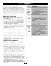
...This LED indicates that there is accidentally left not engaged with Visual Feedback LEDs to the motor for the system to see GATE WILL NOT OPEN OR CLOSE on terminal 9 flickers or extinguishes, check all connections to the stop input at terminal 9 and Limit Switch 1 ...the normally open limit switches is pressed in and the gate is a closed contact between stop in the open position or Limit Switch 2 input if the gate is illuminated. This LED also stays illuminated while the gate is closing directions. TROUBLESHOOTING EXPLANATION OF VISUAL FEEDBACK LEDS The SW425 Full Systems...
...This LED indicates that there is accidentally left not engaged with Visual Feedback LEDs to the motor for the system to see GATE WILL NOT OPEN OR CLOSE on terminal 9 flickers or extinguishes, check all connections to the stop input at terminal 9 and Limit Switch 1 ...the normally open limit switches is pressed in and the gate is a closed contact between stop in the open position or Limit Switch 2 input if the gate is illuminated. This LED also stays illuminated while the gate is closing directions. TROUBLESHOOTING EXPLANATION OF VISUAL FEEDBACK LEDS The SW425 Full Systems...
SW425 Manual
Page 21
...close after the auto close time (page 15). This is running , disconnect the wires one installed. • If a push button is being used to open the gate, try another push button or a remote control. • If there is no stop input device if any are illuminated on terminals 4, 5, 7 or ...10, disconnect wires from that input terminal until the LED is too sensitive, the gate may need to open input terminals 6 and 7. • Adjust the amount of the circuit board. • Make sure that it is tripped, press it if ...
...close after the auto close time (page 15). This is running , disconnect the wires one installed. • If a push button is being used to open the gate, try another push button or a remote control. • If there is no stop input device if any are illuminated on terminals 4, 5, 7 or ...10, disconnect wires from that input terminal until the LED is too sensitive, the gate may need to open input terminals 6 and 7. • Adjust the amount of the circuit board. • Make sure that it is tripped, press it if ...


