SW425 Manual
Page 2
... Location 10 Post Mounting 11 Pad Mounting 11 Control Arm Assembly 11 Gate Bracket and Pipe Arm Installation 12 WIRING Power Wiring Installation 13 Battery Run Installation 14 Solar Powered Installation 14 ADJUSTMENT Right/Left Operation 15 Auto Close Timer Adjustment 15 Gate Sensitivity Adjustment 15 Limit Switch Adjustment 15 Control Connection Diagram 16 Other Common Accessories 17 ACCESSORY WIRING 18 OPERATION AND MAINTENANCE Operator Maintenance 19 Sensitivity Adjustments 19 Control Devices 19 Gate 19 Troubleshooting 20-21 Wiring Diagrams 22-24 NOTES 25 REPAIR PARTS...
... Location 10 Post Mounting 11 Pad Mounting 11 Control Arm Assembly 11 Gate Bracket and Pipe Arm Installation 12 WIRING Power Wiring Installation 13 Battery Run Installation 14 Solar Powered Installation 14 ADJUSTMENT Right/Left Operation 15 Auto Close Timer Adjustment 15 Gate Sensitivity Adjustment 15 Limit Switch Adjustment 15 Control Connection Diagram 16 Other Common Accessories 17 ACCESSORY WIRING 18 OPERATION AND MAINTENANCE Operator Maintenance 19 Sensitivity Adjustments 19 Control Devices 19 Gate 19 Troubleshooting 20-21 Wiring Diagrams 22-24 NOTES 25 REPAIR PARTS...
SW425 Manual
Page 3
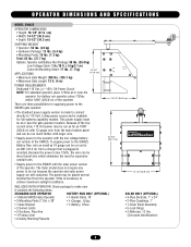
... operator if this is plugged in remotely. x 36" • 1-Charger, 12Vac • 1-Gate Bracket • 1-Battery, 12Vac • 2-Swivel Joints • 2-Sections, Pipe Arm • 1-Primary Arm • 2-Safety Warning Placards SOLAR ONLY (OPTIONAL) • 3-Pipe Sections, 1" x 24" • 2-Pipe Couplings, 1" • 1-Solar Panel Assembly • 5-Lock Rings • 2-Batteries, 12 Vac (See parts identification) 3 The panel may be run version of the operator. OPERATOR DIMENSIONS AND SPECIFICATIONS MODEL SW425 OPERATOR...
... operator if this is plugged in remotely. x 36" • 1-Charger, 12Vac • 1-Gate Bracket • 1-Battery, 12Vac • 2-Swivel Joints • 2-Sections, Pipe Arm • 1-Primary Arm • 2-Safety Warning Placards SOLAR ONLY (OPTIONAL) • 3-Pipe Sections, 1" x 24" • 2-Pipe Couplings, 1" • 1-Solar Panel Assembly • 5-Lock Rings • 2-Batteries, 12 Vac (See parts identification) 3 The panel may be run version of the operator. OPERATOR DIMENSIONS AND SPECIFICATIONS MODEL SW425 OPERATOR...
SW425 Manual
Page 4
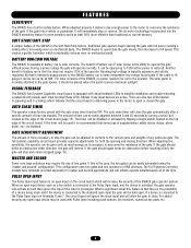
... gates can be used it is prolonged. VISUAL FEEDBACK The SW425 Full Systems Capability circuit board is necessary to the operator. If the timer will be given only as much energy as is equipped with Pulse Open including push buttons, key switches, numerical key pads, etc. 4 The full systems capability circuit board provides separate adjustments for master and second applications and will reliably operate simultaneously all of time has elapsed. MASTER...
... gates can be used it is prolonged. VISUAL FEEDBACK The SW425 Full Systems Capability circuit board is necessary to the operator. If the timer will be given only as much energy as is equipped with Pulse Open including push buttons, key switches, numerical key pads, etc. 4 The full systems capability circuit board provides separate adjustments for master and second applications and will reliably operate simultaneously all of time has elapsed. MASTER...
SW425 Manual
Page 5
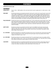
... the circuit board which is used are push buttons, radio receivers, key switches, loop detectors, photo electric beams, 24-hour timers, etc. 5 In this mode of time has elapsed. Stop Input will cause the gate to terminals 9 and 10 on the circuit board after a specific amount of operation the AUTO CLOSE TIMER will still close. Pulse Open Input functions identical to Open Input with the exception that it requires normally open devices are connected to stop at any position. SAFETY INPUT: Normally open...
... the circuit board which is used are push buttons, radio receivers, key switches, loop detectors, photo electric beams, 24-hour timers, etc. 5 In this mode of time has elapsed. Stop Input will cause the gate to terminals 9 and 10 on the circuit board after a specific amount of operation the AUTO CLOSE TIMER will still close. Pulse Open Input functions identical to Open Input with the exception that it requires normally open devices are connected to stop at any position. SAFETY INPUT: Normally open...
SW425 Manual
Page 6
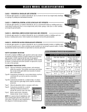
COMMERCIAL/GENERAL ACCESS VEHICULAR GATE OPERATOR A vehicular gate operator (or system) intended for use in plain view on both the open and close directions of entrapment protection. SAFETY ACCESSORY SELECTION All UL325 compliant LiftMaster gate operators will accept external entrapment protection devices to protect people from motorized gate systems. UL325 requires that all installations must have one primary means of entrapment protection and one independent secondary means...
COMMERCIAL/GENERAL ACCESS VEHICULAR GATE OPERATOR A vehicular gate operator (or system) intended for use in plain view on both the open and close directions of entrapment protection. SAFETY ACCESSORY SELECTION All UL325 compliant LiftMaster gate operators will accept external entrapment protection devices to protect people from motorized gate systems. UL325 requires that all installations must have one primary means of entrapment protection and one independent secondary means...
SW425 Manual
Page 7
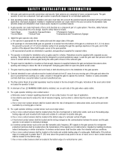
... in a location so that enough clearance is still moving. Outdoor or easily accessible controls shall have a security feature to the gate operator for exposed rollers. 5. Activation of a swing gate is prevented from any point in its wiring arranged so the communication between the gate and adjacent structures when opening and closing to reduce the risk of a vehicular horizontal slide gate. c. A wireless contact sensor shall...
... in a location so that enough clearance is still moving. Outdoor or easily accessible controls shall have a security feature to the gate operator for exposed rollers. 5. Activation of a swing gate is prevented from any point in its wiring arranged so the communication between the gate and adjacent structures when opening and closing to reduce the risk of a vehicular horizontal slide gate. c. A wireless contact sensor shall...

SW425 Manual
Page 9
... force necessary to cause the arm to be installed where visible in BOTH the open and close gate cycles. • Locate entrapment protection devices to protect between moving gate: CAUTION • Entrapment protection devices MUST be mounted using fastening holes. Primary Arm Torque Wrench WARNING SIGN PLACEMENT The gate operator is provided with equal torque, then push on the shaft in the event that the arm...
... force necessary to cause the arm to be installed where visible in BOTH the open and close gate cycles. • Locate entrapment protection devices to protect between moving gate: CAUTION • Entrapment protection devices MUST be mounted using fastening holes. Primary Arm Torque Wrench WARNING SIGN PLACEMENT The gate operator is provided with equal torque, then push on the shaft in the event that the arm...
SW425 Manual
Page 10
... close the gate and make a mark on the ground. The posts are secured by tightening the U-bolt nuts from the hinge. The operator will not run into the bottom of the operator. Place the operator in its approximate location so that the center of the posts (Figure 2). The concrete pad mounting plate is then installed onto the bottom of the shaft...
... close the gate and make a mark on the ground. The posts are secured by tightening the U-bolt nuts from the hinge. The operator will not run into the bottom of the operator. Place the operator in its approximate location so that the center of the posts (Figure 2). The concrete pad mounting plate is then installed onto the bottom of the shaft...

SW425 Manual
Page 11
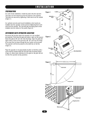
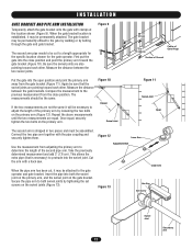
The operator may be concrete pad mounted, use the illustration as shown (Figure 8). Secure the operator from the ground. CONTROL ARM ASSEMBLY Attach the primary arm onto the end of the operator shaft as a guide for the concrete to harden (Figure 5). Figure 7 U-bolts 36" (91 cm) 24" (61 cm) 24" (61 cm) Mounting Stand Concrete Anchor Figure 8 Friction Plate Flat Washer 3/8" Nut 11 3/8" Bolt Flat...
The operator may be concrete pad mounted, use the illustration as shown (Figure 8). Secure the operator from the ground. CONTROL ARM ASSEMBLY Attach the primary arm onto the end of the operator shaft as a guide for the concrete to harden (Figure 5). Figure 7 U-bolts 36" (91 cm) 24" (61 cm) 24" (61 cm) Mounting Stand Concrete Anchor Figure 8 Friction Plate Flat Washer 3/8" Nut 11 3/8" Bolt Flat...
SW425 Manual
Page 12
... gate brackets. Use the measurement from adjusting the primary arm to protrude into both swivel joints by bolting through the gate and gate bracket. Figure 12 Inner Arm Adjustment Bolt Figure 13 Outer Arm Hex Key Set Screw Swivel Joint Secondary Arm 12 When the gate bracket location is established, it may be permanently attached. First put the gate into the open position and point the primary arm away from the close...
... gate brackets. Use the measurement from adjusting the primary arm to protrude into both swivel joints by bolting through the gate and gate bracket. Figure 12 Inner Arm Adjustment Bolt Figure 13 Outer Arm Hex Key Set Screw Swivel Joint Secondary Arm 12 When the gate bracket location is established, it may be permanently attached. First put the gate into the open position and point the primary arm away from the close...

SW425 Manual
Page 13
... control wiring MUST be run in separate conduit. • BEFORE installing power wiring or control stations be on a separate fused line of adequate capacity. • ALL electrical connections MUST be performed until disconnecting the electrical power and locking-out the power via the operator power switch. If the gate operator is switched off. Figure 1 Junction Box Flexible Conduit Make sure that time the unit may be returned to service. • Disconnecting power at this time...
... control wiring MUST be run in separate conduit. • BEFORE installing power wiring or control stations be on a separate fused line of adequate capacity. • ALL electrical connections MUST be performed until disconnecting the electrical power and locking-out the power via the operator power switch. If the gate operator is switched off. Figure 1 Junction Box Flexible Conduit Make sure that time the unit may be returned to service. • Disconnecting power at this time...
SW425 Manual
Page 15
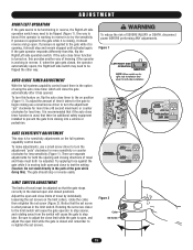
... safety equipment installed to prevent the gate from the switch will cause the gate operator to stop sooner, and rotating away from closing directions of travel by individually loosening the set screw (Figure 2). If pressure is applied to the gate while it is closing use a small screw driver to turn the adjustment "pot" clockwise for more sensitivity or counter clockwise for less time. AUTO CLOSE TIMER ADJUSTMENT With the full systems capability control board...
... safety equipment installed to prevent the gate from the switch will cause the gate operator to stop sooner, and rotating away from closing directions of travel by individually loosening the set screw (Figure 2). If pressure is applied to the gate while it is closing use a small screw driver to turn the adjustment "pot" clockwise for more sensitivity or counter clockwise for less time. AUTO CLOSE TIMER ADJUSTMENT With the full systems capability control board...
SW425 Manual
Page 16
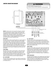
CONTROL CONNECTION DIAGRAM Radio Receiver WARNING To protect against fire and electrocution: CAUTION • Disconnect power BEFORE installing or servicing operator. 1 2 3 4 NOTES: Controls must be far enough from the gate so that the user is found at terminals 6 and 7. 16 The device used must provide normally open contacts. Remove jumper if using N.C. Pulse open until the input is in a non-closed position and can be located in the line of...
CONTROL CONNECTION DIAGRAM Radio Receiver WARNING To protect against fire and electrocution: CAUTION • Disconnect power BEFORE installing or servicing operator. 1 2 3 4 NOTES: Controls must be far enough from the gate so that the user is found at terminals 6 and 7. 16 The device used must provide normally open contacts. Remove jumper if using N.C. Pulse open until the input is in a non-closed position and can be located in the line of...
SW425 Manual
Page 17
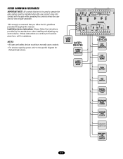
... devices requiring power, refer to operate the gate system must be used to the specific diagram for assistance. Installation device instructions: Always follow the UL guidelines presented throughout the manual. OTHER COMMON ACCESSORIES IMPORTANT NOTE: All controls that are contrary to the advice given here, call for that you follow the instructions provided by the manufacturer when installing and adjusting any control device. If...
... devices requiring power, refer to operate the gate system must be used to the specific diagram for assistance. Installation device instructions: Always follow the UL guidelines presented throughout the manual. OTHER COMMON ACCESSORIES IMPORTANT NOTE: All controls that are contrary to the advice given here, call for that you follow the instructions provided by the manufacturer when installing and adjusting any control device. If...
SW425 Manual
Page 18
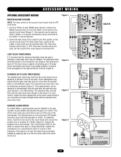
... 2). Connect the negative wire to limit switch 1 NC or limit switch 2 NC for the light and timer is in the gate operator to give extra time to get out of the way of switching up to 10 amps which will add time onto the auto close timer already on the board. ACCESSORY WIRING OPTIONAL ACCESSORY WIRING MASTER/SECOND SYSTEMS NOTE: The timer switch on the second circuit board must stay open for more control, reduce the timer adjustment...
... 2). Connect the negative wire to limit switch 1 NC or limit switch 2 NC for the light and timer is in the gate operator to give extra time to get out of the way of switching up to 10 amps which will add time onto the auto close timer already on the board. ACCESSORY WIRING OPTIONAL ACCESSORY WIRING MASTER/SECOND SYSTEMS NOTE: The timer switch on the second circuit board must stay open for more control, reduce the timer adjustment...
SW425 Manual
Page 19
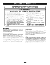
... SW425 is the safety equipment. NING ION OPERATION AND MAINTENANCE IMPORTANT SAWFAETRYNIINNGSTRUCTIONS WARNING To reduce the risk of travel, retest the gate operator. The entrance is not moving. 6. When this happens, the sensitivity adjustments may need to be performed by a LiftMaster professional. 11. Use the emergency release ONLY when the gate is for optimum performance and safety, the following maintenance procedures should reverse relatively easy. Read the owner's manual...
... SW425 is the safety equipment. NING ION OPERATION AND MAINTENANCE IMPORTANT SAWFAETRYNIINNGSTRUCTIONS WARNING To reduce the risk of travel, retest the gate operator. The entrance is not moving. 6. When this happens, the sensitivity adjustments may need to be performed by a LiftMaster professional. 11. Use the emergency release ONLY when the gate is for optimum performance and safety, the following maintenance procedures should reverse relatively easy. Read the owner's manual...
SW425 Manual
Page 20
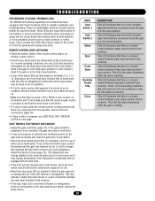
...; Check the limit switch input LEDs on terminals 1 and 3 to the installer or service technician indicating what commands are illuminated on terminal 9 while the gate operator is opening and closing . This LED also stays illuminated while the gate is running and see if the LED flickers or extinguishes. These LEDs give visual information to see GATE WILL NOT OPEN OR CLOSE on the gate such as radio receivers or safety loops. GATE TRAVELS TOO FAR...
...; Check the limit switch input LEDs on terminals 1 and 3 to the installer or service technician indicating what commands are illuminated on terminal 9 while the gate operator is opening and closing . This LED also stays illuminated while the gate is running and see if the LED flickers or extinguishes. These LEDs give visual information to see GATE WILL NOT OPEN OR CLOSE on the gate such as radio receivers or safety loops. GATE TRAVELS TOO FAR...
SW425 Manual
Page 21
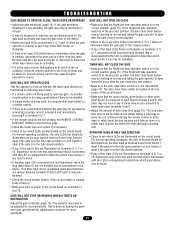
... the radio receiver, push button or other open or safety input devices because each time an open or a safety input is done by turning the open input terminals 5 and 6. TROUBLESHOOTING GATE BEGINS TO OPEN OR CLOSE, THEN STOPS OR REVERSES • Adjust the gate sensitivity (page 15). The timer may not work if any of auto close timer feature may need to the circuit board on the circuit board. Do not continue pressing the remote control or other open input...
... the radio receiver, push button or other open or safety input devices because each time an open or a safety input is done by turning the open input terminals 5 and 6. TROUBLESHOOTING GATE BEGINS TO OPEN OR CLOSE, THEN STOPS OR REVERSES • Adjust the gate sensitivity (page 15). The timer may not work if any of auto close timer feature may need to the circuit board on the circuit board. Do not continue pressing the remote control or other open input...
SW425 Manual
Page 26
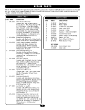
... DESCRIPTION Gate Bracket Motor, 12VDC Transformer, 120V 60HV Limit Switch, SPDT Overload 1.5 Amp Resistor, 1 OHM, 25W OHMITE Sonalert Piezo Alarm Battery Charger, 12V.5A Dual Stg. E K72-40146 Drive Shaft Assembly Complete with your operator. REPAIR PARTS Refer to the parts lists below for replacement parts available for your operator, certain components may be added or removed from these lists. If optional modifications and/or accessories are included with : Drive Shaft, Gear Set, Friction...
... DESCRIPTION Gate Bracket Motor, 12VDC Transformer, 120V 60HV Limit Switch, SPDT Overload 1.5 Amp Resistor, 1 OHM, 25W OHMITE Sonalert Piezo Alarm Battery Charger, 12V.5A Dual Stg. E K72-40146 Drive Shaft Assembly Complete with your operator. REPAIR PARTS Refer to the parts lists below for replacement parts available for your operator, certain components may be added or removed from these lists. If optional modifications and/or accessories are included with : Drive Shaft, Gear Set, Friction...
SW425 Manual
Page 28
... confirmed to state. 01-40108E HOW TO ORDER REPAIR PARTS OUR LARGE SERVICE ORGANIZATION SPANS AMERICA FOR INSTALLATION AND SERVICE INFORMATION CALL OUR TOLL FREE NUMBER 1-800-528-2806 www.liftmaster.com WHEN ORDERING REPAIR PARTS PLEASE SUPPLY THE FOLLOWING INFORMATION: PART NUMBER DESCRIPTION MODEL NUMBER ADDRESS ORDER TO: THE CHAMBERLAIN GROUP, INC. WARRANTY POLICY LIFTMASTER® TWO YEAR LIMITED WARRANTY The Chamberlain Group, Inc. warrants to the first retail...
... confirmed to state. 01-40108E HOW TO ORDER REPAIR PARTS OUR LARGE SERVICE ORGANIZATION SPANS AMERICA FOR INSTALLATION AND SERVICE INFORMATION CALL OUR TOLL FREE NUMBER 1-800-528-2806 www.liftmaster.com WHEN ORDERING REPAIR PARTS PLEASE SUPPLY THE FOLLOWING INFORMATION: PART NUMBER DESCRIPTION MODEL NUMBER ADDRESS ORDER TO: THE CHAMBERLAIN GROUP, INC. WARRANTY POLICY LIFTMASTER® TWO YEAR LIMITED WARRANTY The Chamberlain Group, Inc. warrants to the first retail...


