Installation Manual
Page 16
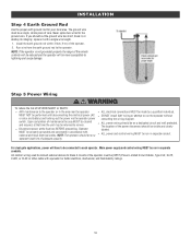
...unit may be made by a qualified individual. Main power supply and control wiring MUST be run the operator without or solar and battery) and locking-out the power via the operator power consulting the wiring diagram. If you should be on a dedicated circuit and well protected. INSTALLATION Step... 4 Earth Ground Rod Use the proper earth ground rod for the ground wire. Install the earth ground rod within 3 feet (.9 m) of wire. MUST NOT be (QPTZ) Power...
...unit may be made by a qualified individual. Main power supply and control wiring MUST be run the operator without or solar and battery) and locking-out the power via the operator power consulting the wiring diagram. If you should be on a dedicated circuit and well protected. INSTALLATION Step... 4 Earth Ground Rod Use the proper earth ground rod for the ground wire. Install the earth ground rod within 3 feet (.9 m) of wire. MUST NOT be (QPTZ) Power...
Installation Manual
Page 45
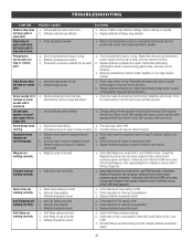
... needed. Defective Expansion board a. Constant pressure to conduct the obstruction test and perform the proper force adjustment that activating edge sensor causes moving gate to Wiring Diagrams). Replace defective expansion board or defective main board a. Check that opens first). Check that Solenoid has power (do not power maglock from control board accessory...
... needed. Defective Expansion board a. Constant pressure to conduct the obstruction test and perform the proper force adjustment that activating edge sensor causes moving gate to Wiring Diagrams). Replace defective expansion board or defective main board a. Check that opens first). Check that Solenoid has power (do not power maglock from control board accessory...
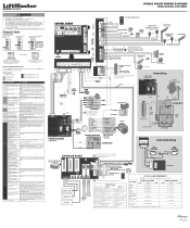
SL585UL SL595UL Three Phase Wiring Diagram
Page 1
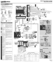
... cycle PHOTOELECTRIC SENSORS for shorts. Black RESET BUTTON ALARM Red Black COM Yellow Yellow HORSE POWER ID 1/2 HP - THREE PHASE WIRING DIAGRAM Models SL585UL and SL595UL To reduce the risk of INJURY or DEATH: • DISCONNECT power BEFORE installing or servicing operator. • Replace... NO C Black Yellow Red 4 4 3 3 Black 2 2 Green 1 1 OPEN Limit Switch Blue NC Black NO C RPM BOARD LiftMaster.com © 2018, LiftMaster All Rights Reserved 01-39240-7 CLOSE EYE/INTERRUPT IF an obstruction occurred, no start condition Motor failed to "20"). If an 73 triggered,...
... cycle PHOTOELECTRIC SENSORS for shorts. Black RESET BUTTON ALARM Red Black COM Yellow Yellow HORSE POWER ID 1/2 HP - THREE PHASE WIRING DIAGRAM Models SL585UL and SL595UL To reduce the risk of INJURY or DEATH: • DISCONNECT power BEFORE installing or servicing operator. • Replace... NO C Black Yellow Red 4 4 3 3 Black 2 2 Green 1 1 OPEN Limit Switch Blue NC Black NO C RPM BOARD LiftMaster.com © 2018, LiftMaster All Rights Reserved 01-39240-7 CLOSE EYE/INTERRUPT IF an obstruction occurred, no start condition Motor failed to "20"). If an 73 triggered,...
SL585UL SL595UL 575V Three Phase Wiring Diagram
Page 1
...required safety testing. If so, erase limits, enter limit setup mode and set switch 1 on AUX RELAY 1 to ON LiftMaster.com © 2018, LiftMaster All Rights Reserved 01-39240-8 If not, disconnect all power, wait 15 seconds, then reconnect power before changing product ID ... between the main board and the 82 (expansion board) expansion board. Nonmonitored contact closure devices are not supported. 575V THREE PHASE WIRING DIAGRAM Models SL585UL and SL595UL To reduce the risk of INJURY or DEATH: • DISCONNECT power BEFORE installing or servicing operator. • Replace...
...required safety testing. If so, erase limits, enter limit setup mode and set switch 1 on AUX RELAY 1 to ON LiftMaster.com © 2018, LiftMaster All Rights Reserved 01-39240-8 If not, disconnect all power, wait 15 seconds, then reconnect power before changing product ID ... between the main board and the 82 (expansion board) expansion board. Nonmonitored contact closure devices are not supported. 575V THREE PHASE WIRING DIAGRAM Models SL585UL and SL595UL To reduce the risk of INJURY or DEATH: • DISCONNECT power BEFORE installing or servicing operator. • Replace...
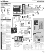
SL585UL SL595UL Single Phase Wiring Diagram
Page 1
... light ON/FLASH Green light OFF * For red light ON when gate is connected to the main control board. SINGLE PHASE WIRING DIAGRAM Models SL585UL and SL595UL To reduce the risk of INJURY or DEATH: • DISCONNECT power BEFORE installing or servicing operator. • Replace... CLS STP COM WIRELESS EDGE KIT Model LMWEKITU PHOTOELECTRIC SENSORS PHOTOELECTRIC SENSORS or EDGE SENSORS SINGLE BUTTON CONTROL STATION N.C. Use ONLY LiftMaster approved entrapment protection devices (refer to start capacitor connections and condition. Product ID Failure 37 Unplug product ID harness then plug...
... light ON/FLASH Green light OFF * For red light ON when gate is connected to the main control board. SINGLE PHASE WIRING DIAGRAM Models SL585UL and SL595UL To reduce the risk of INJURY or DEATH: • DISCONNECT power BEFORE installing or servicing operator. • Replace... CLS STP COM WIRELESS EDGE KIT Model LMWEKITU PHOTOELECTRIC SENSORS PHOTOELECTRIC SENSORS or EDGE SENSORS SINGLE BUTTON CONTROL STATION N.C. Use ONLY LiftMaster approved entrapment protection devices (refer to start capacitor connections and condition. Product ID Failure 37 Unplug product ID harness then plug...


