
SL585UL Product Guide - English
Page 2
...°C) GATE TRAVEL SPEED 11" per Hour - All Rights Reserved. Operator Weight: 240 lbs. Detects Obstructions and Reverses Gate When Closing or Stops/Reverses Gate When Opening MECHANICAL LIMIT SYSTEM - Simplifies Installation and Tr o u b l e s h o o t i n g PROGRAMMABLE AUXILIARY RELAYS - Adjustable Friction Clutch: Helps to 120 Seconds INHERENT REVERSING SENSOR - Supplied) SL585UL AC HEAVY-DUTY INDUSTRIAL SLIDE GATE OPERATOR POWER - 115/208/230VAC Single-Phase; 208/230/460/575VAC 3-Phase (575V Includes Factory-Installed Heater) - c o m / S o l u t i o n - HomeLink®...
...°C) GATE TRAVEL SPEED 11" per Hour - All Rights Reserved. Operator Weight: 240 lbs. Detects Obstructions and Reverses Gate When Closing or Stops/Reverses Gate When Opening MECHANICAL LIMIT SYSTEM - Simplifies Installation and Tr o u b l e s h o o t i n g PROGRAMMABLE AUXILIARY RELAYS - Adjustable Friction Clutch: Helps to 120 Seconds INHERENT REVERSING SENSOR - Supplied) SL585UL AC HEAVY-DUTY INDUSTRIAL SLIDE GATE OPERATOR POWER - 115/208/230VAC Single-Phase; 208/230/460/575VAC 3-Phase (575V Includes Factory-Installed Heater) - c o m / S o l u t i o n - HomeLink®...
Installation Manual
Page 2
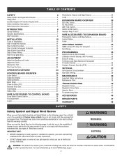
... Sensors 32 Control Station 32 Loops 33 ADDITIONAL WIRING 33 SAMS wiring with relays not energized 33 Field Wiring 34 PROGRAMMING 35 Remote Controls (Not Provided 35 LiftMaster Internet Gateway (Not Provided 36 Erase All Codes 36 To Remove and Erase Monitored Entrapment Protection Devices 36 Constant Pressure Override (CPO 36 SETTINGS 37 Gate Operator Setup Examples 37 Dual Gate Settings 38 MAINTENANCE 39 Important Safety Instructions 39 Maintenance Chart 39 TROUBLESHOOTING 40 Diagnostic Codes 40 Diagnostic Codes...
... Sensors 32 Control Station 32 Loops 33 ADDITIONAL WIRING 33 SAMS wiring with relays not energized 33 Field Wiring 34 PROGRAMMING 35 Remote Controls (Not Provided 35 LiftMaster Internet Gateway (Not Provided 36 Erase All Codes 36 To Remove and Erase Monitored Entrapment Protection Devices 36 Constant Pressure Override (CPO 36 SETTINGS 37 Gate Operator Setup Examples 37 Dual Gate Settings 38 MAINTENANCE 39 Important Safety Instructions 39 Maintenance Chart 39 TROUBLESHOOTING 40 Diagnostic Codes 40 Diagnostic Codes...
Installation Manual
Page 5
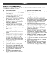
... to limit travel to ASTM F2200 for barbed wire shall not be less than 16 in contact with this specification. 5 The pedestrian gate shall be installed in a location such that the gate covers in accordance with a powered gate operator. Exception: All other than the exceptions listed in the vicinity of an automated vehicular gate, a separate pedestrian gate shall be provided. Vehicular horizontal slide gate. pedestrian access and...
... to limit travel to ASTM F2200 for barbed wire shall not be less than 16 in contact with this specification. 5 The pedestrian gate shall be installed in a location such that the gate covers in accordance with a powered gate operator. Exception: All other than the exceptions listed in the vicinity of an automated vehicular gate, a separate pedestrian gate shall be provided. Vehicular horizontal slide gate. pedestrian access and...
Installation Manual
Page 21
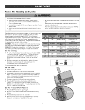
... MODE EXPLANATION Control board not powered Handing not set Handing set to the direction of the solid LED Handing set to allow for each operator. Gate MUST reverse on which direction the gate should be set for additional travel. 4. The force is set the limits but should be set where the gate will have to be set to flash and the operator beeps. 2. For dual gate applications the limits will stop in the open the gate. 2. Press and release...
... MODE EXPLANATION Control board not powered Handing not set Handing set to the direction of the solid LED Handing set to allow for each operator. Gate MUST reverse on which direction the gate should be set for additional travel. 4. The force is set the limits but should be set where the gate will have to be set to flash and the operator beeps. 2. For dual gate applications the limits will stop in the open the gate. 2. Press and release...
Installation Manual
Page 31
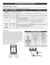
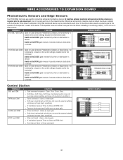
... display, connect an external light (low voltage). Green light wired to control external devices, for Aux Relay 1. The 1, 2, and 3 LEDs will sound. Red/green light functionality, see below . Cycle count cannot be reset or changed. Function of relay contact activation determined by being pushed off . Use with SAMS (Sequenced Access Management System, jointly with by switch settings. NOTE: The expansion board will flash the cycle count 3 times then all the LEDs will blink out...
... display, connect an external light (low voltage). Green light wired to control external devices, for Aux Relay 1. The 1, 2, and 3 LEDs will sound. Red/green light functionality, see below . Cycle count cannot be reset or changed. Function of relay contact activation determined by being pushed off . Use with SAMS (Sequenced Access Management System, jointly with by switch settings. NOTE: The expansion board will flash the cycle count 3 times then all the LEDs will blink out...
Installation Manual
Page 32
... the operator at OPEN limit l Overrides an Open or Close command WIRING EXAMPLE 32 Open, Stop, Close, Stop, ... closes an open gate l Close command - l Soft Open, Soft Close, Soft Stop (maintained switch does not override external safeties and does not reset alarm condition) l Open command - Only ONE monitored device may be connected to -Close at the time of the device. TERMINALS FUNCTION EYE ONLY and COM Open or Close Direction Photoelectric Sensors, the functionality is based on the switch settings (located...
... the operator at OPEN limit l Overrides an Open or Close command WIRING EXAMPLE 32 Open, Stop, Close, Stop, ... closes an open gate l Close command - l Soft Open, Soft Close, Soft Stop (maintained switch does not override external safeties and does not reset alarm condition) l Open command - Only ONE monitored device may be connected to -Close at the time of the device. TERMINALS FUNCTION EYE ONLY and COM Open or Close Direction Photoelectric Sensors, the functionality is based on the switch settings (located...
Installation Manual
Page 35
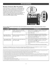
... the range of the remote controls DO NOT straighten the antenna. PROGRAMMING Remote Controls (Not Provided) A total of 50 Security+ 2.0® remote controls or KPW250 keypads and 2 keyless entries (1 PIN for each remote control button as an open, close, and stop . 1. The memory will time out of programming mode after 30 seconds. 2. The operator will automatically exit learn mode (operator will beep and green XMITTER LED will time out of programming mode after 30 seconds. 2. This equipment generates, uses and can be determined by turning...
... the range of the remote controls DO NOT straighten the antenna. PROGRAMMING Remote Controls (Not Provided) A total of 50 Security+ 2.0® remote controls or KPW250 keypads and 2 keyless entries (1 PIN for each remote control button as an open, close, and stop . 1. The memory will time out of programming mode after 30 seconds. 2. The operator will automatically exit learn mode (operator will beep and green XMITTER LED will time out of programming mode after 30 seconds. 2. This equipment generates, uses and can be determined by turning...
Installation Manual
Page 36
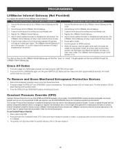
... the open " or "closed . 7. Use the feature only in learn mode for three minutes. 6. The operator will stop when either "open limit press and release the reset button 3 times (on primary gate) to put primary operator into High Band Learn Mode (the operator will beep as it enters learn mode). Press and release the LEARN button (operator will beep and green XMITTER LED will stay in line of sight of the gate when no obstructions to travel are not working properly. To Remove...
... the open " or "closed . 7. Use the feature only in learn mode for three minutes. 6. The operator will stop when either "open limit press and release the reset button 3 times (on primary gate) to put primary operator into High Band Learn Mode (the operator will beep as it enters learn mode). Press and release the LEARN button (operator will beep and green XMITTER LED will stay in line of sight of the gate when no obstructions to travel are not working properly. To Remove...
Installation Manual
Page 37
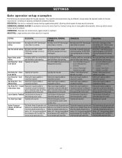
... or more gated entrances/exits, allowing vehicle access trumps security concerns COMMERCIAL: Business site where security (gate closed) is important INDUSTRIAL: Large business site where security is manually tampered with by being pushed off of close limit. CLOSE EYES/Interrupt loop reverses a closing gate. In attempt to indicate if gate is required SETTING RESIDENTIAL COMMERCIAL/GENERAL ACCESS COMMERCIAL INDUSTRIAL Quick Close switch setting Normally set to ON for the gate operator. Use with SAMS (Sequence Access 1. light). 2. light). Aux Relay Out - Aux...
... or more gated entrances/exits, allowing vehicle access trumps security concerns COMMERCIAL: Business site where security (gate closed) is important INDUSTRIAL: Large business site where security is manually tampered with by being pushed off of close limit. CLOSE EYES/Interrupt loop reverses a closing gate. In attempt to indicate if gate is required SETTING RESIDENTIAL COMMERCIAL/GENERAL ACCESS COMMERCIAL INDUSTRIAL Quick Close switch setting Normally set to ON for the gate operator. Use with SAMS (Sequence Access 1. light). 2. light). Aux Relay Out - Aux...
Installation Manual
Page 39
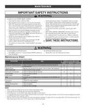
... servicing. To tighten the drive chain adjust either of same type and rating. Operator moving. l ALL maintenance MUST be taken at that time the unit may have no obstructions to gate hardware. Read the owner's manual. Keep the remote control away from the gate. To protect against fire: l Replace ONLY with gate controls. For continued protection against fire and electrocution: l DISCONNECT power (AC or solar and battery) BEFORE installing or servicing operator...
... servicing. To tighten the drive chain adjust either of same type and rating. Operator moving. l ALL maintenance MUST be taken at that time the unit may have no obstructions to gate hardware. Read the owner's manual. Keep the remote control away from the gate. To protect against fire: l Replace ONLY with gate controls. For continued protection against fire and electrocution: l DISCONNECT power (AC or solar and battery) BEFORE installing or servicing operator...
Installation Manual
Page 41
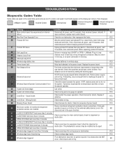
... Error Product ID Failure Exit Loop Error Shadow Loop Error Interrupt Loop Error Wireless edge battery low Power board fault Run-Distance Error Brownout occurred Wireless Second Operator Communication Error System AC Overvoltage System AC Undervoltage Limit Error - Failure or missing loop (SHORT or OPEN - LiftMaster Plug-in wireless edge. Replace batteries in Loop Detector only) Check loop wiring throughout connection. Relay fault detected in . Check limit positions and proper switch function. If rebooting, ensure enough time for presence of power to force a fresh boot. Replace...
... Error Product ID Failure Exit Loop Error Shadow Loop Error Interrupt Loop Error Wireless edge battery low Power board fault Run-Distance Error Brownout occurred Wireless Second Operator Communication Error System AC Overvoltage System AC Undervoltage Limit Error - Failure or missing loop (SHORT or OPEN - LiftMaster Plug-in wireless edge. Replace batteries in Loop Detector only) Check loop wiring throughout connection. Relay fault detected in . Check limit positions and proper switch function. If rebooting, ensure enough time for presence of power to force a fresh boot. Replace...
Installation Manual
Page 42
... on the limit shaft, and wiring. Make sure the current sensor is powered. Non-monitored contact closure devices are NOT moving, or moving , failure is engaged and free to the main control board. Check edges for an open or short. If the fault continues, replace the power board. Ensure operator is connected to move . If the gate and motor are not supported. Check the current sensor harness for...
... on the limit shaft, and wiring. Make sure the current sensor is powered. Non-monitored contact closure devices are NOT moving, or moving , failure is engaged and free to the main control board. Check edges for an open or short. If the fault continues, replace the power board. Ensure operator is connected to move . If the gate and motor are not supported. Check the current sensor harness for...
Installation Manual
Page 44
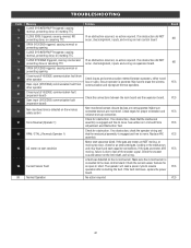
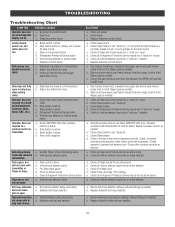
... Reset button d. Check Stop button is not "stuck on " sensor e. Review Exit loop detector settings. Replace defective control board a. b. Replace wireless control as needed . POSSIBLE CAUSES a. Check Open and Close command input LEDs b. Vehicle loop detector active a. Check Stop button is not "stuck on", or verify that the stop button is active c. Gate is active c. Exit vehicle detector setup incorrectly b. Vehicle detector setup incorrectly b. Repair gate as needed. Repair gate as needed . Gate does not move gate, and ensure gate moves easily limit...
... Reset button d. Check Stop button is not "stuck on " sensor e. Review Exit loop detector settings. Replace defective control board a. b. Replace wireless control as needed . POSSIBLE CAUSES a. Check Open and Close command input LEDs b. Vehicle loop detector active a. Check Stop button is not "stuck on", or verify that the stop button is active c. Gate is active c. Exit vehicle detector setup incorrectly b. Vehicle detector setup incorrectly b. Repair gate as needed. Repair gate as needed . Gate does not move gate, and ensure gate moves easily limit...
Installation Manual
Page 45
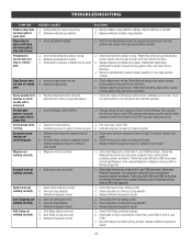
... board wiring. Defective Expansion board a. AUX Relay setting incorrect b. Check that obstructing photoelectric sensor causes moving gate to N.C. Check operation of both operator's Bipart switch settings. TROUBLESHOOTING SYMPTOM Shadow loop does not keep gate at open or close is needed. Edge Sensor does not stop or reverse gate. On dual-gate system, incorrect gate opens first or closes first. Alarm beeps when running. Maglock not working correctly. Solenoid lock not working correctly. AUX Relay not working correctly. Defective vehicle loop detector a. Force adjustment...
... board wiring. Defective Expansion board a. AUX Relay setting incorrect b. Check that obstructing photoelectric sensor causes moving gate to N.C. Check operation of both operator's Bipart switch settings. TROUBLESHOOTING SYMPTOM Shadow loop does not keep gate at open or close is needed. Edge Sensor does not stop or reverse gate. On dual-gate system, incorrect gate opens first or closes first. Alarm beeps when running. Maglock not working correctly. Solenoid lock not working correctly. AUX Relay not working correctly. Defective vehicle loop detector a. Force adjustment...
Installation Manual
Page 48
... Windsor Drive Oak Brook, IL 60523 LiftMaster.com © 2018, The Chamberlain Group, Inc. - THIS LIMITED WARRANTY DOES NOT COVER NON-DEFECT DAMAGE, DAMAGE CAUSED BY IMPROPER INSTALLATION, OPERATION OR CARE (INCLUDING, BUT NOT LIMITED TO ABUSE, MISUSE, FAILURE TO PROVIDE REASONABLE AND NECESSARY MAINTENANCE, UNAUTHORIZED REPAIRS OR ANY ALTERATIONS TO THIS PRODUCT), LABOR CHARGES FOR REINSTALLING A REPAIRED OR REPLACED UNIT, OR REPLACEMENT OF BATTERIES...
... Windsor Drive Oak Brook, IL 60523 LiftMaster.com © 2018, The Chamberlain Group, Inc. - THIS LIMITED WARRANTY DOES NOT COVER NON-DEFECT DAMAGE, DAMAGE CAUSED BY IMPROPER INSTALLATION, OPERATION OR CARE (INCLUDING, BUT NOT LIMITED TO ABUSE, MISUSE, FAILURE TO PROVIDE REASONABLE AND NECESSARY MAINTENANCE, UNAUTHORIZED REPAIRS OR ANY ALTERATIONS TO THIS PRODUCT), LABOR CHARGES FOR REINSTALLING A REPAIRED OR REPLACED UNIT, OR REPLACEMENT OF BATTERIES...
SL585UL SL595UL Three Phase Wiring Diagram
Page 1
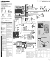
... wireless safety system Make sure the attached edge/eye is the code itself (31-99, example" "31"). FIRE DEPARTMENT EXIT LOOP ACCESS CONTROL DEVICE INTERRUPT LOOP or OR PHOTOELECTRIC SENSORS for shorts. Yellow 1 HP - SWITCH Attach to metal chassis Purple White Black L3 Purple L2 White L1 Black Green JUNCTION BOX INCOMING POWER 480 Vac Power Wiring with "01" and going up to operator. 57 Limit Error - Use ONLY LiftMaster...
... wireless safety system Make sure the attached edge/eye is the code itself (31-99, example" "31"). FIRE DEPARTMENT EXIT LOOP ACCESS CONTROL DEVICE INTERRUPT LOOP or OR PHOTOELECTRIC SENSORS for shorts. Yellow 1 HP - SWITCH Attach to metal chassis Purple White Black L3 Purple L2 White L1 Black Green JUNCTION BOX INCOMING POWER 480 Vac Power Wiring with "01" and going up to operator. 57 Limit Error - Use ONLY LiftMaster...
SL585UL SL595UL 575V Three Phase Wiring Diagram
Page 1
... ON LEDs will show the code sequence number followed by saving one in the close and one or both of the limits again. Green light wired to operator. GATE STATE CLOSED AUX RELAY 1 SWITCHES 1 OFF 2 OFF 3 OFF Red light OFF* AUX RELAY 2 SWITCHES 1 ON 2 ON 3 ON Green light OFF OPENING OPEN CLOSING Defined Mid Stop Undefined Mid Stop Timer more than 5 seconds Red light ON/FLASH Green light OFF * For red light ON when gate is closed, set limits. 575V THREE PHASE WIRING DIAGRAM Models SL585UL...
... ON LEDs will show the code sequence number followed by saving one in the close and one or both of the limits again. Green light wired to operator. GATE STATE CLOSED AUX RELAY 1 SWITCHES 1 OFF 2 OFF 3 OFF Red light OFF* AUX RELAY 2 SWITCHES 1 ON 2 ON 3 ON Green light OFF OPENING OPEN CLOSING Defined Mid Stop Undefined Mid Stop Timer more than 5 seconds Red light ON/FLASH Green light OFF * For red light ON when gate is closed, set limits. 575V THREE PHASE WIRING DIAGRAM Models SL585UL...
SL585UL SL595UL Single Phase Wiring Diagram
Page 1
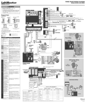
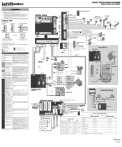
... CURRENT MOTOR DRIVE RPM & LIMITS ALARM EXP. 24 VAC IN SENSOR ID RESET BOARD GND 21 Red Blue Orange Yellow Green Gray Purple Black White 10 9 8 7 6 5 4 3 2 1 4 3 2 1 21 4321 White PRODUCT ID SL585UL - Blue SL595UL - Yellow 1 HP - GATE STATE CLOSED AUX RELAY 1 SWITCHES 1 OFF 2 OFF 3 OFF Red light OFF* AUX RELAY 2 SWITCHES 1 ON 2 ON 3 ON Green light OFF OPENING OPEN CLOSING Defined Mid Stop Undefined Mid Stop Timer more than 3 minutes Check wired input...
... CURRENT MOTOR DRIVE RPM & LIMITS ALARM EXP. 24 VAC IN SENSOR ID RESET BOARD GND 21 Red Blue Orange Yellow Green Gray Purple Black White 10 9 8 7 6 5 4 3 2 1 4 3 2 1 21 4321 White PRODUCT ID SL585UL - Blue SL595UL - Yellow 1 HP - GATE STATE CLOSED AUX RELAY 1 SWITCHES 1 OFF 2 OFF 3 OFF Red light OFF* AUX RELAY 2 SWITCHES 1 ON 2 ON 3 ON Green light OFF OPENING OPEN CLOSING Defined Mid Stop Undefined Mid Stop Timer more than 3 minutes Check wired input...

UL 325-Listed Gate Operators Guide
Page 6
.../STOP OPERATION AND MID-TRAVEL REVERSAL EXTEND HARDWARE LIFE OF THE GATE AND OPERATOR. WIRELESS DUAL-GATE COMMUNICATION SYNCHRONIZES GATE OPENING/ CLOSING AND ELIMINATES EXPENSIVE DRIVEWAY TRENCHING COSTS. PARTY PASS ALLOWS FOR THE GATES TO BE HELD OPEN FOR AN EXTENDED PERIOD OF TIME. INHERENT REVERSING SENSOR DETECTS OBSTRUCTIONS AND REVERSES GATE WHEN CLOSING OR STOPS/REVERSES THE GATE WHEN OPENING. max. UL® LISTED GATE OPERATORS WITH MONITORED SAFETY ENTRAPMENT PROTECTION DEVICES. SOLAR PANEL KIT Uses the sun to power...
.../STOP OPERATION AND MID-TRAVEL REVERSAL EXTEND HARDWARE LIFE OF THE GATE AND OPERATOR. WIRELESS DUAL-GATE COMMUNICATION SYNCHRONIZES GATE OPENING/ CLOSING AND ELIMINATES EXPENSIVE DRIVEWAY TRENCHING COSTS. PARTY PASS ALLOWS FOR THE GATES TO BE HELD OPEN FOR AN EXTENDED PERIOD OF TIME. INHERENT REVERSING SENSOR DETECTS OBSTRUCTIONS AND REVERSES GATE WHEN CLOSING OR STOPS/REVERSES THE GATE WHEN OPENING. max. UL® LISTED GATE OPERATORS WITH MONITORED SAFETY ENTRAPMENT PROTECTION DEVICES. SOLAR PANEL KIT Uses the sun to power...

UL 325-Listed Gate Operators Guide
Page 32
... EASY TO PAIR TRANSMITTER AND RECEIVER VIA SMART BUTTON. SAFE AND SECURE PRESSURE-SENSITIVE EDGE SENDS SIGNAL TO STOP AND/OR REVERSE GATE OPERATION WHEN SENSING OBSTRUCTIONS. MONITORED THROUGHBEAM PHOTO EYES Enhanced through-beam now with gate operator firmware 4.2 or higher. TOTAL SOLUTION ACCESSORIES: MONITORED SMALL PROFILE RESISTIVE EDGE Pressure-sensitive edge stops and/or reverses gate when obstructed. WIRELESS KEYPAD Provides constant pressure override to control gate operator if safety devices fault yet...
... EASY TO PAIR TRANSMITTER AND RECEIVER VIA SMART BUTTON. SAFE AND SECURE PRESSURE-SENSITIVE EDGE SENDS SIGNAL TO STOP AND/OR REVERSE GATE OPERATION WHEN SENSING OBSTRUCTIONS. MONITORED THROUGHBEAM PHOTO EYES Enhanced through-beam now with gate operator firmware 4.2 or higher. TOTAL SOLUTION ACCESSORIES: MONITORED SMALL PROFILE RESISTIVE EDGE Pressure-sensitive edge stops and/or reverses gate when obstructed. WIRELESS KEYPAD Provides constant pressure override to control gate operator if safety devices fault yet...


