MGJ User's Guide Manual
Page 2
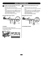
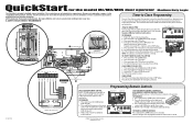
...;N TO PROGRAM Photo Eye Press and hold the LEARN and STOP buttons until the LED goes out (approximately 3 seconds). Your new operator is released before reaching the close . • Open override that is installed. (See accessories page for safety device to B2 wiring (option D) when Monitored Safety Device is removed, the operator will automatically convert to reverse. Disconnect then reconnect power to close command. Refer to the close limit switch. The LED on the logic board will...
...;N TO PROGRAM Photo Eye Press and hold the LEARN and STOP buttons until the LED goes out (approximately 3 seconds). Your new operator is released before reaching the close . • Open override that is installed. (See accessories page for safety device to B2 wiring (option D) when Monitored Safety Device is removed, the operator will automatically convert to reverse. Disconnect then reconnect power to close command. Refer to the close limit switch. The LED on the logic board will...
MGJ User's Guide Manual
Page 3
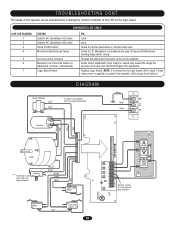
... TTC 1 C18 D14 LEARN STOP CLOSE OPEN LED 2 3 4 5 6 7 K2 LT C29 R24 P1 D9 LMEP1 LMEP2 COM INTRLK STOP CLOSE OPEN LEARN STOP CLOSE OPEN LEDD14 1 2 3 4 5 6 7 Photo Eye 3 NOTE: The operator will automatically convert to B2 wiring (option D) when Monitored Safety Device is installed. (See accessories page for safety device to reverse. NON-MONITORED SAFETY DEVICE MONITORED SAFETY DEVICE Sensing Edge TO PROGRAM Start with operator in factory default C2 mode. D B2 WIRING TYPE WITH MONITORED...
... TTC 1 C18 D14 LEARN STOP CLOSE OPEN LED 2 3 4 5 6 7 K2 LT C29 R24 P1 D9 LMEP1 LMEP2 COM INTRLK STOP CLOSE OPEN LEARN STOP CLOSE OPEN LEDD14 1 2 3 4 5 6 7 Photo Eye 3 NOTE: The operator will automatically convert to B2 wiring (option D) when Monitored Safety Device is installed. (See accessories page for safety device to reverse. NON-MONITORED SAFETY DEVICE MONITORED SAFETY DEVICE Sensing Edge TO PROGRAM Start with operator in factory default C2 mode. D B2 WIRING TYPE WITH MONITORED...
MGJ User's Guide Manual
Page 4
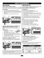
... (2) this receiver and/or transmitter are prohibited, except for changing the code setting or replacing the battery. Press and release the LEARN button (LED will go out). Begin with TTC C2 RADIO OPERATION OPEN CLOSE STOP X X X X X (3 button X remote) X X REVERSE WHILE CLOSING X TTC RESET X X WHEN OPEN X 4 TO PROGRAM 1. Press and release the TTC button a second time. 4. BASIC PROGRAMMING REMOTE CONTROLS SINGLE BUTTON REMOTE CONTROL Built in 315 MHz radio receiver permits as many as 20 Security✚® remote controls or dip switch remote controls in...
... (2) this receiver and/or transmitter are prohibited, except for changing the code setting or replacing the battery. Press and release the LEARN button (LED will go out). Begin with TTC C2 RADIO OPERATION OPEN CLOSE STOP X X X X X (3 button X remote) X X REVERSE WHILE CLOSING X TTC RESET X X WHEN OPEN X 4 TO PROGRAM 1. Press and release the TTC button a second time. 4. BASIC PROGRAMMING REMOTE CONTROLS SINGLE BUTTON REMOTE CONTROL Built in 315 MHz radio receiver permits as many as 20 Security✚® remote controls or dip switch remote controls in...
MGJ User's Guide Manual
Page 5
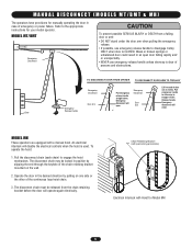
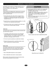
... instructions for Model MH 5 Emergency disconnect will disable the electrical controls when the hoist is used. Pull the disconnect chain (sash chain) to engage roll pin. AVERTISSEMENT TO DISCONNECT DOOR FROM OPENER TO RECONNECT DOOR ARM TO TROLLEY NOTICE Emergency Emergency Disconnect Door Arm ATTEEmergNencyTION Pull emergency Disconnect release handle straight down. To operate the hoist: 1. M A N U A L D I S C O N N E C T ( M O D E L S M T / BWMATRN& INMGH ) The operators have provisions for manually operating the door in case of the continuous loop hoist chain...
... instructions for Model MH 5 Emergency disconnect will disable the electrical controls when the hoist is used. Pull the disconnect chain (sash chain) to engage roll pin. AVERTISSEMENT TO DISCONNECT DOOR FROM OPENER TO RECONNECT DOOR ARM TO TROLLEY NOTICE Emergency Emergency Disconnect Door Arm ATTEEmergNencyTION Pull emergency Disconnect release handle straight down. To operate the hoist: 1. M A N U A L D I S C O N N E C T ( M O D E L S M T / BWMATRN& INMGH ) The operators have provisions for manually operating the door in case of the continuous loop hoist chain...
MGJ User's Guide Manual
Page 7
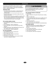
... electrocution, disconnect ALL electric power BEFORE performing ANY maintenance. Door should stop .) TEST LIMIT ADJUSTMENT 1. Allow door to fully close to make sure they are not set properly, contact your installing dealer. Test all controls and safety devices to obstruction and reverse if sensing edge is installed. 4. Press STOP button. (The door should open the door only. 1. The door AVERTISSEMENT should close . Door should close . In C2 wiring the remote control will flash 7 times on power up. Press remote control button. 2. WARNING To...
... electrocution, disconnect ALL electric power BEFORE performing ANY maintenance. Door should stop .) TEST LIMIT ADJUSTMENT 1. Allow door to fully close to make sure they are not set properly, contact your installing dealer. Test all controls and safety devices to obstruction and reverse if sensing edge is installed. 4. Press STOP button. (The door should open the door only. 1. The door AVERTISSEMENT should close . Door should close . In C2 wiring the remote control will flash 7 times on power up. Press remote control button. 2. WARNING To...
MGJ User's Guide Manual
Page 8
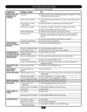
....liftmaster.com CONDITION POSSIBLE CAUSE OPERATOR WILL NOT RESPOND TO ANY COMMANDS No power Accessory failure Possible component failure OPERATOR MAKES Operator requires adjustment NOISE BUT DOOR DOES NOT MOVE DOOR DRIFTS AFTER OPERATOR STOPS Operator or door requires adjustment DOOR OPENS/CLOSES Operator requires adjustment TOO FAR DOOR REVERSES UNEXPECTEDLY Safety device activated RADIO FUNCTIONALITY NO RESPONSE REMOTE CANNOT BE PROGRAMMED POOR RANGE Remote control is not programmed Low battery Low battery Low battery Possible radio interference FIX ➤ Check circuit...
....liftmaster.com CONDITION POSSIBLE CAUSE OPERATOR WILL NOT RESPOND TO ANY COMMANDS No power Accessory failure Possible component failure OPERATOR MAKES Operator requires adjustment NOISE BUT DOOR DOES NOT MOVE DOOR DRIFTS AFTER OPERATOR STOPS Operator or door requires adjustment DOOR OPENS/CLOSES Operator requires adjustment TOO FAR DOOR REVERSES UNEXPECTEDLY Safety device activated RADIO FUNCTIONALITY NO RESPONSE REMOTE CANNOT BE PROGRAMMED POOR RANGE Remote control is not programmed Low battery Low battery Low battery Possible radio interference FIX ➤ Check circuit...
MJ5011E QuickStart-2008 Manual
Page 1
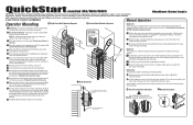
... door again electronically. c Release the disconnect chain or reset the emergency egress device to wall or mounting bracket. 7 Align sprockets, insert key into keyway, and secure. 8 Place hand chain around door sprocket and join roller chain ends together with adjustments. 7 Align Sprockets Optimum Distance 12-15" MODEL MJ This operator has a floor level disconnect chain to the operator BEFORE manually operating your door. When operator is used . These instructions are aligned. Make sure the operator output shaft is obstructed. Connect...
... door again electronically. c Release the disconnect chain or reset the emergency egress device to wall or mounting bracket. 7 Align sprockets, insert key into keyway, and secure. 8 Place hand chain around door sprocket and join roller chain ends together with adjustments. 7 Align Sprockets Optimum Distance 12-15" MODEL MJ This operator has a floor level disconnect chain to the operator BEFORE manually operating your door. When operator is used . These instructions are aligned. Make sure the operator output shaft is obstructed. Connect...
MJ5011E QuickStart-2008 Manual
Page 2
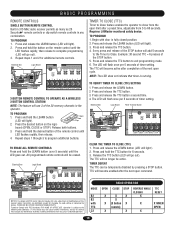
... TTC = 6 presses of timer setting. Press and release the LEARN button (LED will light). 3. Release the TTC button (LED will flash once per 5 seconds of the next open command. Programming Remote Controls 7 6 5 3 White/Black White LiftMaster® CPS Safety Sensors SINGLE BUTTON REMOTE CONTROL Built in 315 MHz radio receiver permits as many as 20 Security✚® remote controls or dip switch remote controls in fully closed position. 2. QuickStart for 6 seconds. 3. The LED will go out). 3. TO PROGRAM 1. Electrical Box Logic Board 014A1030 J4 C32 TP1...
... TTC = 6 presses of timer setting. Press and release the LEARN button (LED will light). 3. Release the TTC button (LED will flash once per 5 seconds of the next open command. Programming Remote Controls 7 6 5 3 White/Black White LiftMaster® CPS Safety Sensors SINGLE BUTTON REMOTE CONTROL Built in 315 MHz radio receiver permits as many as 20 Security✚® remote controls or dip switch remote controls in fully closed position. 2. QuickStart for 6 seconds. 3. The LED will go out). 3. TO PROGRAM 1. Electrical Box Logic Board 014A1030 J4 C32 TP1...
MJ5011E Installation-2008 Manual
Page 2
... SPECIFICATIONS 4 CARTON INVENTORY 5 PREPARATION 5 ASSEMBLY 6 TYPICAL INSTALLATION 6-10 INSTALLATION 11-12 ADJUSTMENT 13 OPTIONAL SAFETY DEVICE CONFIGURATION 14-15 LOGIC BOARD LAYOUT 16 BASIC PROGRAMMING 17-19 TESTING 20 EMERGENCY DISCONNECT SYSTEM 21 TROUBLESHOOTING 22-23 DIAGRAM 23 REPAIR PARTS - ELECTRICAL BOX 21 REPAIR PARTS KITS 24-27 OPERATOR NOTES 28-30 ACCESSORIES 31 CONTROL CONNECTIONS BACK COVER SAFETY INFORMATION WARNING Mechanical CWWAAAURRTNINOIINNNGG Electrical CAWUATRIONNING WARNING IMPORTANT NOTES: • BEFORE attempting to your commercial door...
... SPECIFICATIONS 4 CARTON INVENTORY 5 PREPARATION 5 ASSEMBLY 6 TYPICAL INSTALLATION 6-10 INSTALLATION 11-12 ADJUSTMENT 13 OPTIONAL SAFETY DEVICE CONFIGURATION 14-15 LOGIC BOARD LAYOUT 16 BASIC PROGRAMMING 17-19 TESTING 20 EMERGENCY DISCONNECT SYSTEM 21 TROUBLESHOOTING 22-23 DIAGRAM 23 REPAIR PARTS - ELECTRICAL BOX 21 REPAIR PARTS KITS 24-27 OPERATOR NOTES 28-30 ACCESSORIES 31 CONTROL CONNECTIONS BACK COVER SAFETY INFORMATION WARNING Mechanical CWWAAAURRTNINOIINNNGG Electrical CAWUATRIONNING WARNING IMPORTANT NOTES: • BEFORE attempting to your commercial door...
MJ5011E Installation-2008 Manual
Page 3
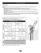
Safety devices are highly recommended by the manufacturer. • Radio receiver: A factory installed radio receiver allows remote controls, keyless entries and other remote command devices to be programmed to the operator. • Timer To Close: The Timer To Close feature allows the door to Basic Programming Section for use on the wiring type. Intended for rolling sheet doors. Not recommended for descriptions of wiring types, requirements and programming. Steel Insulated --- 24 ga. 22 ga. Steel...
Safety devices are highly recommended by the manufacturer. • Radio receiver: A factory installed radio receiver allows remote controls, keyless entries and other remote command devices to be programmed to the operator. • Timer To Close: The Timer To Close feature allows the door to Basic Programming Section for use on the wiring type. Intended for rolling sheet doors. Not recommended for descriptions of wiring types, requirements and programming. Steel Insulated --- 24 ga. 22 ga. Steel...
MJ5011E Installation-2008 Manual
Page 4
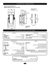
... AMPS 6.0 Amps ELECTRICAL OPERATOR VOLTAGE 115Vac, Single Phase, 60 Hz WIRING TYPE C2 (Standard) B2 Configurable (See Basic Programming Section) CONTROL WIRING 16-22 AWG MECHANICAL DOOR SPEED Approximately 9" (23 cm) / second depending on door setup OUTPUT FORCE 125 ft. Supports both monitored and non-monitored safety devices including LiftMaster CPS photo-eyes and industry standard sensing edges. OUTPUT RPM: MJ 80 RPM MH 80 RPM MHS 38.6 RPM LIMIT ADJUST Fully adjustable up to...
... AMPS 6.0 Amps ELECTRICAL OPERATOR VOLTAGE 115Vac, Single Phase, 60 Hz WIRING TYPE C2 (Standard) B2 Configurable (See Basic Programming Section) CONTROL WIRING 16-22 AWG MECHANICAL DOOR SPEED Approximately 9" (23 cm) / second depending on door setup OUTPUT FORCE 125 ft. Supports both monitored and non-monitored safety devices including LiftMaster CPS photo-eyes and industry standard sensing edges. OUTPUT RPM: MJ 80 RPM MH 80 RPM MHS 38.6 RPM LIMIT ADJUST Fully adjustable up to...
MJ5011E Installation-2008 Manual
Page 5
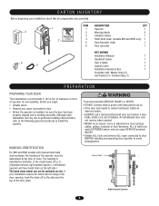
... you begin: • Disable locks. • Remove any ropes connected to avoid entanglement. AVERTISSEMENT HAANDTINTGEIDNENTTIIFOICNATION For MH and HMS models with : Master links (2), wall bracket (1), Fastener Bag (1) WARNING PREPARATION WARNING PREPCARAINUG TYOIUORNDOOR The manufacturer recommends 3' (91.4 cm) of clearance in the door opening, hook the chain off to remain functional, install an interlock switch. • ALWAYS call a trained professional door serviceman if door binds, sticks or is...
... you begin: • Disable locks. • Remove any ropes connected to avoid entanglement. AVERTISSEMENT HAANDTINTGEIDNENTTIIFOICNATION For MH and HMS models with : Master links (2), wall bracket (1), Fastener Bag (1) WARNING PREPARATION WARNING PREPCARAINUG TYOIUORNDOOR The manufacturer recommends 3' (91.4 cm) of clearance in the door opening, hook the chain off to remain functional, install an interlock switch. • ALWAYS call a trained professional door serviceman if door binds, sticks or is...
MJ5011E Installation-2008 Manual
Page 13
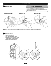
... operation. • Secure clutch nut with cotter pin. WARNING 1 CADAJUUST TTHIEOLIMNITS ADJUSTMENT WARNING WARNING To avoid SERIOUS personal INJURY or DEATH from electrocution, disconnect electric power BEFORE moving limit nuts or adjusting clutch nut. Depress retaining plate Adjust OPEN limit Retaining Plate OPEN Limit Nut OPEN Limit Switch CLOSE Limit Nut AVERTISSEMENCLTOSE Limit Switch ATTENTION Increase Door Travel Adjust CLOSE limit Increase Door Travel Decrease Door Travel AVERTISSEMENT AVERTISSEMENT Decrease Door Travel SAFETY Limit Switch NOTE: When retaining plate is released...
... operation. • Secure clutch nut with cotter pin. WARNING 1 CADAJUUST TTHIEOLIMNITS ADJUSTMENT WARNING WARNING To avoid SERIOUS personal INJURY or DEATH from electrocution, disconnect electric power BEFORE moving limit nuts or adjusting clutch nut. Depress retaining plate Adjust OPEN limit Retaining Plate OPEN Limit Nut OPEN Limit Switch CLOSE Limit Nut AVERTISSEMENCLTOSE Limit Switch ATTENTION Increase Door Travel Adjust CLOSE limit Increase Door Travel Decrease Door Travel AVERTISSEMENT AVERTISSEMENT Decrease Door Travel SAFETY Limit Switch NOTE: When retaining plate is released...
MJ5011E Installation-2008 Manual
Page 17
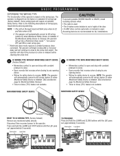
... close limit switch. Disconnect then reconnect power to reset wiring type. ** Restricted close mode requires a constant pressure close limit. Electrical Box Logic Board 014A1030 J4 C32 TP1 C20 R25 C9 C21 U1 D7 D5 U4 D6 D4 AAUUX AANNTT J2 L5 ^^^^ R27 TTC 1 C18 D14 LEARN STOP CLOSE OPEN LED 2 3 4 5 6 7 K2 LT C29 R24 P1 D9 LMEP1 LMEP2 COM INTRLK STOP CLOSE OPEN LEARN STOP CLOSE OPEN LEDD14 1 2 3 4 5 6 7 Photo Eye TO PROGRAM Press and hold the LEARN and STOP buttons until the LED...
... close limit switch. Disconnect then reconnect power to reset wiring type. ** Restricted close mode requires a constant pressure close limit. Electrical Box Logic Board 014A1030 J4 C32 TP1 C20 R25 C9 C21 U1 D7 D5 U4 D6 D4 AAUUX AANNTT J2 L5 ^^^^ R27 TTC 1 C18 D14 LEARN STOP CLOSE OPEN LED 2 3 4 5 6 7 K2 LT C29 R24 P1 D9 LMEP1 LMEP2 COM INTRLK STOP CLOSE OPEN LEARN STOP CLOSE OPEN LEDD14 1 2 3 4 5 6 7 Photo Eye TO PROGRAM Press and hold the LEARN and STOP buttons until the LED...
MJ5011E Installation-2008 Manual
Page 19
... 1 and 2 for changing the code setting or replacing the battery. Press the desired button on the remote control until the LED flashes rapidly, then release to Comply with FCC and or Industry Canada (IC) rules, adjustment or modifications of timer setting. Requires LiftMaster monitored safety device. Press and release the LEARN button (LED will go out). Press and release the TTC button. 3. The LED will be temporarily disabled by pressing a STOP button. Electrical Box Logic Board Timer To Close Button 014A1030 J4...
... 1 and 2 for changing the code setting or replacing the battery. Press the desired button on the remote control until the LED flashes rapidly, then release to Comply with FCC and or Industry Canada (IC) rules, adjustment or modifications of timer setting. Requires LiftMaster monitored safety device. Press and release the LEARN button (LED will go out). Press and release the TTC button. 3. The LED will be temporarily disabled by pressing a STOP button. Electrical Box Logic Board Timer To Close Button 014A1030 J4...
MJ5011E Installation-2008 Manual
Page 20
...Release CLOSE button. Allow the door to obstruction and reverse if sensing edge is installed. 4. Press the CLOSE button. The door should close to fully close. 5. The door AVERTISSEMENT should not close . Press CLOSE button. Press remote control button. 2. Door should close if photo eyes are not set properly, remove power and adjust limits (refer to Adjustment section). Allow the door to fully close . Allow door to fully open. 3. Press STOP button. (The door should stop .) TEST LIMIT ADJUSTMENT 1. Open the door. 2. In C2 wiring the remote control will flash 7 times...
...Release CLOSE button. Allow the door to obstruction and reverse if sensing edge is installed. 4. Press the CLOSE button. The door should close to fully close. 5. The door AVERTISSEMENT should not close . Press CLOSE button. Press remote control button. 2. Door should close if photo eyes are not set properly, remove power and adjust limits (refer to Adjustment section). Allow the door to fully close . Allow door to fully open. 3. Press STOP button. (The door should stop .) TEST LIMIT ADJUSTMENT 1. Open the door. 2. In C2 wiring the remote control will flash 7 times...
MJ5011E Installation-2008 Manual
Page 21
... the chain and secure in an open door falling rapidly and/or unexpectedly. • NEVER use emergency disconnect ONLY when door is used . Release the disconnect chain or reset the emergeny egress device to engage the hoist mechanism. When operator is clear of the chain keeper mounted on the wall. An electrical interlock will not function. Electrical Interlock with Hoist for Models MH and MHS Keyhole Bracket ADVERTENCIA PRECAUCIÓN Manual Disconnect...
... the chain and secure in an open door falling rapidly and/or unexpectedly. • NEVER use emergency disconnect ONLY when door is used . Release the disconnect chain or reset the emergeny egress device to engage the hoist mechanism. When operator is clear of the chain keeper mounted on the wall. An electrical interlock will not function. Electrical Interlock with Hoist for Models MH and MHS Keyhole Bracket ADVERTENCIA PRECAUCIÓN Manual Disconnect...
MJ5011E Installation-2008 Manual
Page 22
...; Close and Open the door. C) Stuck button on 3-button control station ➤ Verify that all LiftMaster 315MHz remote control devices. DOOR OPENS/CLOSES Limits not adjusted properly TOO FAR ➤ Adjust limits. Allow to close by holding the CLOSE button for proper operation. B) Clutch slipping ➤ Adjust clutch, see ADJUSTMENT section. A) Low battery ➤ Replace battery. B) Brake not releasing (if present) ➤ Verify brake assembly operation and wiring. TROUBLESHOOTING Technical Support 1-800-528-2806 CONDITION POSSIBLE CAUSE FIX OPERATOR...
...; Close and Open the door. C) Stuck button on 3-button control station ➤ Verify that all LiftMaster 315MHz remote control devices. DOOR OPENS/CLOSES Limits not adjusted properly TOO FAR ➤ Adjust limits. Allow to close by holding the CLOSE button for proper operation. B) Clutch slipping ➤ Adjust clutch, see ADJUSTMENT section. A) Low battery ➤ Replace battery. B) Brake not releasing (if present) ➤ Verify brake assembly operation and wiring. TROUBLESHOOTING Technical Support 1-800-528-2806 CONDITION POSSIBLE CAUSE FIX OPERATOR...
MJ5011E Installation-2008 Manual
Page 23
... to install external door interlock. NOTE: It is normal for the logic board LED to flash 7 times when power is not used, wires are capped together. Operating in B2 mode Stuck CLOSE button Monitored Safety Device failure Incorrect motor direction Maximum run timer has timed out (Maximum run time = 90 seconds) Logic Board Failure FIX none none Check for stuck close button or shorted close wire Check for assistance. Replace Logic Board. Check clutch adjustment. Call Technical Support for : 1) Misaligned or blocked photo eyes...
... to install external door interlock. NOTE: It is normal for the logic board LED to flash 7 times when power is not used, wires are capped together. Operating in B2 mode Stuck CLOSE button Monitored Safety Device failure Incorrect motor direction Maximum run timer has timed out (Maximum run time = 90 seconds) Logic Board Failure FIX none none Check for stuck close button or shorted close wire Check for assistance. Replace Logic Board. Check clutch adjustment. Call Technical Support for : 1) Misaligned or blocked photo eyes...
MJ5011E Installation-2008 Manual
Page 31
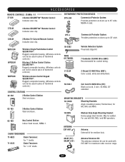
... Wire (500'): Recommended for TO MJ, MH, and MHS.RING 10-9095 ANTENNA EXT-ANT OPEN Medium Duty Angle Mounting Bracket: CLOSE Heavy-gauge steel bracket. For use with EXT-ANT for medium duty. OPEN CLOSE PRESS TO R ING OPEN ACCESSORIES REMOTE CONTROLS 315MHz 371LM OPEN 3-Button SECURITY✚® Remote Control: Includes visor clip. Key Control Station: Indoor flush mount, NEMA 1. OPEN CLOSE 31 OPEN CLOSE 02-103 ^OPEN COLOPESNE O STOP CLOSE 02-109 OPEN CLOSE 3-Button Control Station: Steel enclosure. OPEN CLOSE MOUNTING BRACKETS 10-12360 Mounting Brackets: Angle mounting...
... Wire (500'): Recommended for TO MJ, MH, and MHS.RING 10-9095 ANTENNA EXT-ANT OPEN Medium Duty Angle Mounting Bracket: CLOSE Heavy-gauge steel bracket. For use with EXT-ANT for medium duty. OPEN CLOSE PRESS TO R ING OPEN ACCESSORIES REMOTE CONTROLS 315MHz 371LM OPEN 3-Button SECURITY✚® Remote Control: Includes visor clip. Key Control Station: Indoor flush mount, NEMA 1. OPEN CLOSE 31 OPEN CLOSE 02-103 ^OPEN COLOPESNE O STOP CLOSE 02-109 OPEN CLOSE 3-Button Control Station: Steel enclosure. OPEN CLOSE MOUNTING BRACKETS 10-12360 Mounting Brackets: Angle mounting...


