
LGJ Manual
Page 2
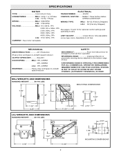
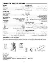
SAFETY DISCONNECT Floor level disconnect for optional control settings and operating modes. 380V, 50Hz, 3Ph 460V, 60Hz, 3Ph LGJ: 115V, 60Hz, 1Ph LIMIT ADJUST Linear driven, fully adjustable screw type cams. Adjustable to the bottom edge of door A REVERSING EDGE IS STRONGLY RECOMMENDED FOR ALL COMMERCIAL OPERATOR INSTALLATIONS. SPECIFICATIONS MOTOR TYPE Intermittent Duty ELECTRICAL TRANSFORMER 24VAC HORSEPOWER MGJ: 1/2Hp 1 or 3 Phase LGJ: 1/4 Hp 1 Phase CONTROL STATION: ......NEMA 1 three button station. REVERSING EDGE Optional) Electric or pneumatic...
SAFETY DISCONNECT Floor level disconnect for optional control settings and operating modes. 380V, 50Hz, 3Ph 460V, 60Hz, 3Ph LGJ: 115V, 60Hz, 1Ph LIMIT ADJUST Linear driven, fully adjustable screw type cams. Adjustable to the bottom edge of door A REVERSING EDGE IS STRONGLY RECOMMENDED FOR ALL COMMERCIAL OPERATOR INSTALLATIONS. SPECIFICATIONS MOTOR TYPE Intermittent Duty ELECTRICAL TRANSFORMER 24VAC HORSEPOWER MGJ: 1/2Hp 1 or 3 Phase LGJ: 1/4 Hp 1 Phase CONTROL STATION: ......NEMA 1 three button station. REVERSING EDGE Optional) Electric or pneumatic...
LGJ Manual
Page 3
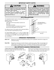
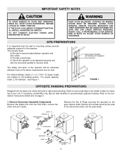
... digit in the model number for model LGJ. Model MGJ: Shipped from the limit chain, remove the chain and set the yoke aside. If necessary, model MGJ may also be adversely affected if any of your unit. b) Provide a level base. Refer to the door shaft. Remove Disconnect Assembly Components Remove the master link from the factory for the operator. KEEP DOOR BALANCED. STICKING OR BINDING DOORS MUST BE REPAIRED. DOORS, DOOR SPRINGS, CABLES, PULLEYS, BRACKETS AND THEIR HARDWARE...
... digit in the model number for model LGJ. Model MGJ: Shipped from the limit chain, remove the chain and set the yoke aside. If necessary, model MGJ may also be adversely affected if any of your unit. b) Provide a level base. Refer to the door shaft. Remove Disconnect Assembly Components Remove the master link from the factory for the operator. KEEP DOOR BALANCED. STICKING OR BINDING DOORS MUST BE REPAIRED. DOORS, DOOR SPRINGS, CABLES, PULLEYS, BRACKETS AND THEIR HARDWARE...
LGJ Manual
Page 8
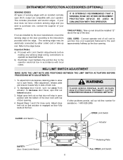
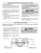
... PERSONAL INJURY OR DEATH FROM ELECTROCUTION, DISCONNECT ELECTRIC POWER BEFORE MANUALLY MOVING LIMIT NUTS. 3. If other problems persist, call our toll-free number for close limit nut so that door will stop in open (N.O.) output are compatible with Limit Switch Adjustments before making any sensing edge wiring connections to purchase one, contact the supplier of your operator. The sensing edge may be installed 12" above the top of the...
... PERSONAL INJURY OR DEATH FROM ELECTROCUTION, DISCONNECT ELECTRIC POWER BEFORE MANUALLY MOVING LIMIT NUTS. 3. If other problems persist, call our toll-free number for close limit nut so that door will stop in open (N.O.) output are compatible with Limit Switch Adjustments before making any sensing edge wiring connections to purchase one, contact the supplier of your operator. The sensing edge may be installed 12" above the top of the...

LGJ Manual
Page 9
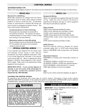
... is mounted Motor Side Up: Set dip switch SW1 - pole #2 to "OFF" position. See the figure below for correct setting. Auxiliary limit switches to a half-open position. (see page 17, Manual Operation) WARNING C. pole #2 to "ON" position. Limit switch -B- Limit Switch -A(Bottom Switch) Dip Switch SW1 9 If your operator is "OFF": Limit switch -A- is the close limit. limit switches. Test Limit Travel Manually move the door to control other functions are two(2) limit nuts on circuit board. After completing the wiring connections on...
... is mounted Motor Side Up: Set dip switch SW1 - pole #2 to "OFF" position. See the figure below for correct setting. Auxiliary limit switches to a half-open position. (see page 17, Manual Operation) WARNING C. pole #2 to "ON" position. Limit switch -B- Limit Switch -A(Bottom Switch) Dip Switch SW1 9 If your operator is "OFF": Limit switch -A- is the close limit. limit switches. Test Limit Travel Manually move the door to control other functions are two(2) limit nuts on circuit board. After completing the wiring connections on...
LGJ Manual
Page 11
... control connection diagrams on the inside cover the electrical box to determine the type of control station. Entry Controls: OPEN control requiring maintained contact. Operational Features: REVERSE (if closing Door Lock Sensing Circuit. Generally a three button station (OPEN/CLOSE/STOP) is exceeded. IF CONTROL STATION CANNOT BE INSTALLED WHERE DOOR IS VISIBLE, OR IF ANY DEVICE OTHER THAN THE CONTROL STATION IS USED TO ACTIVATE THE DOOR, A REVERSING EDGE MUST BE INSTALLED ON THE BOTTOM OF CAUTION THE DOOR. CONTROL WIRING DETERMINE WIRING...
... control connection diagrams on the inside cover the electrical box to determine the type of control station. Entry Controls: OPEN control requiring maintained contact. Operational Features: REVERSE (if closing Door Lock Sensing Circuit. Generally a three button station (OPEN/CLOSE/STOP) is exceeded. IF CONTROL STATION CANNOT BE INSTALLED WHERE DOOR IS VISIBLE, OR IF ANY DEVICE OTHER THAN THE CONTROL STATION IS USED TO ACTIVATE THE DOOR, A REVERSING EDGE MUST BE INSTALLED ON THE BOTTOM OF CAUTION THE DOOR. CONTROL WIRING DETERMINE WIRING...

LGJ Manual
Page 24
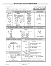
MGJ CONTROL CONNECTION DIAGRAM IMPORTANT NOTES: (Refer to page 15 for model LGJ control connections) 1) The 3-Button Control Station provided must be placed between termianls 3 and 4. pullswitch, single button, loop detector, card key or such device. 3 BUTTON STATION or 3 POSITION KEYSWITCH w/ SPRING RETURN TO CENTER AND STOP BUTTON STANDARD 1234 2 OR MORE 1234 KEY LOCKOUT 1234 Open Close Stop Open Close Stop Open Close Stop Open Close Stop Keyswitch ALL CONTROL WIRING TYPES ALL CONTROL WIRING TYPES 2 BUTTON STATION or 3 POSITION KEYSWITCH w/ SPRING RETURN TO CENTER STANDARD...
MGJ CONTROL CONNECTION DIAGRAM IMPORTANT NOTES: (Refer to page 15 for model LGJ control connections) 1) The 3-Button Control Station provided must be placed between termianls 3 and 4. pullswitch, single button, loop detector, card key or such device. 3 BUTTON STATION or 3 POSITION KEYSWITCH w/ SPRING RETURN TO CENTER AND STOP BUTTON STANDARD 1234 2 OR MORE 1234 KEY LOCKOUT 1234 Open Close Stop Open Close Stop Open Close Stop Open Close Stop Keyswitch ALL CONTROL WIRING TYPES ALL CONTROL WIRING TYPES 2 BUTTON STATION or 3 POSITION KEYSWITCH w/ SPRING RETURN TO CENTER STANDARD...
MGJ S-SERIES Manual
Page 4
... INJURY. IF THE DOOR LOCK NEEDS TO REMAIN FUNCTIONAL, INSTALL AN INTERLOCK SWITCH. Remove the screws securing the yoke to prevent play between . MAN TO MOVE OR ADJUST DOOR SPRINGS OR HARDWARE. Remove Disconnect Assembly Components Remove the master link from the factory for the operator. Shaft Support Bracket with the drive shaft parallel to be fastened securely and with Bearing (Not Supplied) Door Sprocket The safety and wear of your unit. IMPORTANT SAFETY NOTES CAUTION WARNINWG...
... INJURY. IF THE DOOR LOCK NEEDS TO REMAIN FUNCTIONAL, INSTALL AN INTERLOCK SWITCH. Remove the screws securing the yoke to prevent play between . MAN TO MOVE OR ADJUST DOOR SPRINGS OR HARDWARE. Remove Disconnect Assembly Components Remove the master link from the factory for the operator. Shaft Support Bracket with the drive shaft parallel to be fastened securely and with Bearing (Not Supplied) Door Sprocket The safety and wear of your unit. IMPORTANT SAFETY NOTES CAUTION WARNINWG...
MGJ S-SERIES Manual
Page 7
... wall approximately halfway up reel. Adjust close cycle. If not pre-installed by either coiled cord or take-up the door opening . 4. Repeat Steps 1 and 2 for SS90 Input) 7 CLOSE Limit Switch WARNING TO AVOID SERIOUS PERSONAL INJURY OR DEATH FROM ELECTROCUTION, DISCONNECT ELECTRIC POWER BEFORE MANUALLY MOVING LIMIT NUTS. WARNING W AN ELECTRIC SENSING EDGE IS REQUIRED WHEN USING THIS OPERATOR IN CONJUNCTION WITH THE SS90 FIRE DOOR CONTROLLER. LIMIT SWITCH ADJUSTMENT...
... wall approximately halfway up reel. Adjust close cycle. If not pre-installed by either coiled cord or take-up the door opening . 4. Repeat Steps 1 and 2 for SS90 Input) 7 CLOSE Limit Switch WARNING TO AVOID SERIOUS PERSONAL INJURY OR DEATH FROM ELECTROCUTION, DISCONNECT ELECTRIC POWER BEFORE MANUALLY MOVING LIMIT NUTS. WARNING W AN ELECTRIC SENSING EDGE IS REQUIRED WHEN USING THIS OPERATOR IN CONJUNCTION WITH THE SS90 FIRE DOOR CONTROLLER. LIMIT SWITCH ADJUSTMENT...
MGJ S-SERIES Manual
Page 16
..., The Chamberlain Group, Inc. Terminal Block - MGJ CONTROL CONNECTION DIAGRAM IMPORTANT NOTES: 1) The 3-Button Control Station provided must be connected for operation. 2) If a STOP button is Used INTERCONNECTIONS SS90 FIRE DOOR CONTROLLER SS90 FIRE CONTROL TERMINAL BLOCK MGJ "SS90" TERMINAL BLOCK 4 5 4 5 ONE 2 OR MORE RESIDENTIAL RADIO CONTROLS R1 R2 R3 EXTERNAL TERMINAL BLOCK RADIO CONTROL ALL CONTROL WIRING TYPES 01-18600A NOTE: There are listed by Board - STANDARD 1234 3 BUTTON STATION or 3 POSITION KEYSWITCH w/ SPRING RETURN...
..., The Chamberlain Group, Inc. Terminal Block - MGJ CONTROL CONNECTION DIAGRAM IMPORTANT NOTES: 1) The 3-Button Control Station provided must be connected for operation. 2) If a STOP button is Used INTERCONNECTIONS SS90 FIRE DOOR CONTROLLER SS90 FIRE CONTROL TERMINAL BLOCK MGJ "SS90" TERMINAL BLOCK 4 5 4 5 ONE 2 OR MORE RESIDENTIAL RADIO CONTROLS R1 R2 R3 EXTERNAL TERMINAL BLOCK RADIO CONTROL ALL CONTROL WIRING TYPES 01-18600A NOTE: There are listed by Board - STANDARD 1234 3 BUTTON STATION or 3 POSITION KEYSWITCH w/ SPRING RETURN...
MGJ User's Guide Manual
Page 2
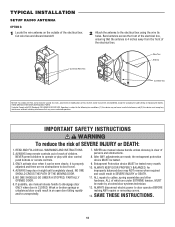
... LED on purchasing a quality, LiftMaster Medium Duty existing 315 MHz product line as well as a Timer To Close (TTC) Commercial Door Operator. NON-MONITORED SAFETY DEVICE CAUTION To prevent possible SEVERE INJURY or DEATH, install reversing sensors when: • The radio is used. • The 3-button control station is used. MONITORED SAFETY DEVICE C31 C31 Sensing Edge RESET TO C2 WIRING TYPE (Factory Default) Remove any opening device. • Wiring for Monitored Safety Devices...
... LED on purchasing a quality, LiftMaster Medium Duty existing 315 MHz product line as well as a Timer To Close (TTC) Commercial Door Operator. NON-MONITORED SAFETY DEVICE CAUTION To prevent possible SEVERE INJURY or DEATH, install reversing sensors when: • The radio is used. • The 3-button control station is used. MONITORED SAFETY DEVICE C31 C31 Sensing Edge RESET TO C2 WIRING TYPE (Factory Default) Remove any opening device. • Wiring for Monitored Safety Devices...
MGJ User's Guide Manual
Page 4
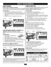
... the desired button on the remote control until the LED flashes rapidly, then release to complete programming (LED will add 5 seconds to the Timer to Close. Release both buttons. 3. Press and hold the button on the logic board (OPEN, CLOSE or STOP). All programmed remote controls will light.) 2. NOTE: The LED does not indicate that may not cause harmful interference, and (2) this receiver and/or transmitter are prohibited, except for changing the code setting or replacing the battery. Tested to...
... the desired button on the remote control until the LED flashes rapidly, then release to complete programming (LED will add 5 seconds to the Timer to Close. Release both buttons. 3. Press and hold the button on the logic board (OPEN, CLOSE or STOP). All programmed remote controls will light.) 2. NOTE: The LED does not indicate that may not cause harmful interference, and (2) this receiver and/or transmitter are prohibited, except for changing the code setting or replacing the battery. Tested to...
MGJ Manual
Page 11
... customer service department @ 1-800-528-2806. IMPORTANT NOTE: If your operator was placed on the inside cover the AVERTISSEMENT electrical box to determine the type of door(s). Control Station 4' Approximate 11 We recommend that time the unit may be returned to service. • Disconnect power at the fuse box BEFORE proceeding. EMENDETTERMINE WIRING TYPE AVERTISSEMENT ON Refer to the wiring diagram located on terminal #2 in the electrical enclosure. See close...
... customer service department @ 1-800-528-2806. IMPORTANT NOTE: If your operator was placed on the inside cover the AVERTISSEMENT electrical box to determine the type of door(s). Control Station 4' Approximate 11 We recommend that time the unit may be returned to service. • Disconnect power at the fuse box BEFORE proceeding. EMENDETTERMINE WIRING TYPE AVERTISSEMENT ON Refer to the wiring diagram located on terminal #2 in the electrical enclosure. See close...

Installation Manual
Page 4
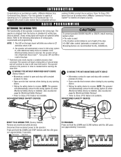
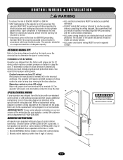
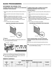
... automatically reverse a closing door. • Radio receiver: A factory installed radio receiver allows remote controls, keyless entries and other remote command devices to be programmed to the operator. • Timer-To-Close: The Timer-to-Close feature allows the door to Basic Programming Section for use on vertical or high-lift sectional doors, or rolling door products. Some wiring types will provide years of wiring types, requirements and programming. FT SECTIONAL DOOR ROLLING DOOR Intended for descriptions of reliable and safe operation. Steel...
... automatically reverse a closing door. • Radio receiver: A factory installed radio receiver allows remote controls, keyless entries and other remote command devices to be programmed to the operator. • Timer-To-Close: The Timer-to-Close feature allows the door to Basic Programming Section for use on vertical or high-lift sectional doors, or rolling door products. Some wiring types will provide years of wiring types, requirements and programming. FT SECTIONAL DOOR ROLLING DOOR Intended for descriptions of reliable and safe operation. Steel...
Installation Manual
Page 6
... + 122˚ F (-20˚ C to + 50˚ C) UL Listed to 40˚ C: Chamberlain tested to provide non-contact safety protection. Your model may look different than the model illustrated. ^OPEN ^CLOSE O STOP 3-Button Station Warning Placard Operator Operator Drive Sprocket Door/Operator Chain NOT SHOWN Installation Manual Quickstart Guide User's Guide Entrapment Warning Placard Installation Hardware Bag, Complete with: Master links (2), Wall bracket (1), Fastener Bag (1) Door sprocket 6 Hoist Hand Chain Models MH and MHS ONLY lbs / sec. MJ Floor level...
... + 122˚ F (-20˚ C to + 50˚ C) UL Listed to 40˚ C: Chamberlain tested to provide non-contact safety protection. Your model may look different than the model illustrated. ^OPEN ^CLOSE O STOP 3-Button Station Warning Placard Operator Operator Drive Sprocket Door/Operator Chain NOT SHOWN Installation Manual Quickstart Guide User's Guide Entrapment Warning Placard Installation Hardware Bag, Complete with: Master links (2), Wall bracket (1), Fastener Bag (1) Door sprocket 6 Hoist Hand Chain Models MH and MHS ONLY lbs / sec. MJ Floor level...
Installation Manual
Page 14
... disconnect electric power to door travel. 4. TYPICAL INSTALLATION SETUP RADIO ANTENNA OPTION B 1 Locate the wire antenna on the outside of the electrical box. Operation is properly adjusted and there are under EXTREME tension, MUST be made , the entrapment protection device MUST be tested. 9. ONLY activate door when it is subject to cables, spring assemblies and other hardware, ALL of which are no obstructions to door operator BEFORE making ANY repairs or removing covers...
... disconnect electric power to door travel. 4. TYPICAL INSTALLATION SETUP RADIO ANTENNA OPTION B 1 Locate the wire antenna on the outside of the electrical box. Operation is properly adjusted and there are under EXTREME tension, MUST be made , the entrapment protection device MUST be tested. 9. ONLY activate door when it is subject to cables, spring assemblies and other hardware, ALL of which are no obstructions to door operator BEFORE making ANY repairs or removing covers...
Installation Manual
Page 19
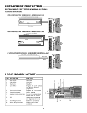
...TTC ^^^^ 1 LEARN STOP CLOSE OPEN LEDD14 2 3 4 LMEP1 LMEP2 COM INTRLK STOP CLOSE OPEN 5 6 7 AUX ANT AUX ANT TTC ^^^^ 1 LEARN STOP CLOSE OPEN LEDD14 2 3 4 LMEP1 LMEP2 COM INTRLK STOP CLOSE OPEN 5 6 7 LOGIC BOARD LAYOUT ITEM 1 2 3 DESCRIPTION Open Button Close Button Stop Button FUNCTION Open Door Close Door Stop Door 31 5 42 4 Learn Button Programs the remote controls and performs additional programming 5 Timer-to-Close Button Programs the Timer-to-Close 6 Purple Wire Antenna Primary Antenna 7 Auxiliary Antenna Connection For use with external antenna kit -EXT...
...TTC ^^^^ 1 LEARN STOP CLOSE OPEN LEDD14 2 3 4 LMEP1 LMEP2 COM INTRLK STOP CLOSE OPEN 5 6 7 AUX ANT AUX ANT TTC ^^^^ 1 LEARN STOP CLOSE OPEN LEDD14 2 3 4 LMEP1 LMEP2 COM INTRLK STOP CLOSE OPEN 5 6 7 LOGIC BOARD LAYOUT ITEM 1 2 3 DESCRIPTION Open Button Close Button Stop Button FUNCTION Open Door Close Door Stop Door 31 5 42 4 Learn Button Programs the remote controls and performs additional programming 5 Timer-to-Close Button Programs the Timer-to-Close 6 Purple Wire Antenna Primary Antenna 7 Auxiliary Antenna Connection For use with external antenna kit -EXT...
Installation Manual
Page 21
... close . • Open override that reverses when closing by any monitored entrapment protection devices. 2 Turn the main power OFF and then ON to restore the operator to the FACTORY DEFAULT setting. 1 2 3 4 5 6 7 To Reset to B2 with Monitored Entrapment Protection Device: 1 Press and hold the LEARN and CLOSE buttons until the LED goes out (approximately 3 seconds). REMOTE CONTROLS MODE B2 B2 with TTC C2 OPEN X X X RADIO OPERATION CLOSE X X (3-button remote) STOP X X X 21 REVERSE WHILE CLOSING X X X TTC RESET...
... close . • Open override that reverses when closing by any monitored entrapment protection devices. 2 Turn the main power OFF and then ON to restore the operator to the FACTORY DEFAULT setting. 1 2 3 4 5 6 7 To Reset to B2 with Monitored Entrapment Protection Device: 1 Press and hold the LEARN and CLOSE buttons until the LED goes out (approximately 3 seconds). REMOTE CONTROLS MODE B2 B2 with TTC C2 OPEN X X X RADIO OPERATION CLOSE X X (3-button remote) STOP X X X 21 REVERSE WHILE CLOSING X X X TTC RESET...
Installation Manual
Page 22
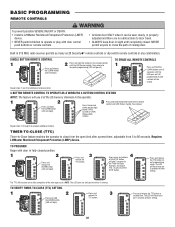
... hold 2 button on the remote control until LED flashes rapidly, then release. 1 Press and hold the button on the logic 2 AUX AANUT X ANT AUX ANT the LEARN button 3 board (OPEN, ^^^^ TTC 1 3 LEARN STOP CLOSE OPEN LEDD14 2 3 4 LMEP1 LMEP2 COM INTRLK STOP CLOSE OPEN 5 (LED will go out). All programmed remote controls will flash once per 5 seconds of timer setting. permit anyone to exit programming mode. ATTENTION 3-BUTTON REMOTE CONTROL TO OPERATE AS A WIRELESS 3-BUTTON CONTROL STATION NOTE: The feature will use 3 of...
... hold 2 button on the remote control until LED flashes rapidly, then release. 1 Press and hold the button on the logic 2 AUX AANUT X ANT AUX ANT the LEARN button 3 board (OPEN, ^^^^ TTC 1 3 LEARN STOP CLOSE OPEN LEDD14 2 3 4 LMEP1 LMEP2 COM INTRLK STOP CLOSE OPEN 5 (LED will go out). All programmed remote controls will flash once per 5 seconds of timer setting. permit anyone to exit programming mode. ATTENTION 3-BUTTON REMOTE CONTROL TO OPERATE AS A WIRELESS 3-BUTTON CONTROL STATION NOTE: The feature will use 3 of...
Installation Manual
Page 24
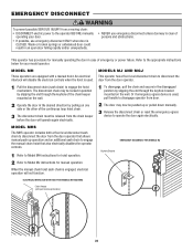
... manually. 3 Release the disconnect chain or reset the emergency egress device to disconnect the interlock will disable the electrical controls when the hoist is engaged, electrical operation will operate again electrically. 2 The door may be locked in the disengaged mechanism. Or if emergency egress device is CLOSED. ADVERTENCIA When the manual chain hoist sash chain is used , mounted on the wall. Keyhole Bracket CIA 1 ADVERTENCIA Refer to Model MJ instructions for manually operating the door in an open door...
... manually. 3 Release the disconnect chain or reset the emergency egress device to disconnect the interlock will disable the electrical controls when the hoist is engaged, electrical operation will operate again electrically. 2 The door may be locked in the disengaged mechanism. Or if emergency egress device is CLOSED. ADVERTENCIA When the manual chain hoist sash chain is used , mounted on the wall. Keyhole Bracket CIA 1 ADVERTENCIA Refer to Model MJ instructions for manually operating the door in an open door...
Installation Manual
Page 25
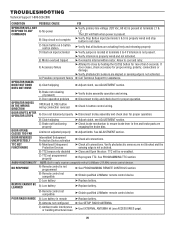
... ➤ Adjust clutch, see ACCESSORIES page). 25 POOR RADIO RANGE A) Low battery in radio receiver compatible with all connections. G) Possible component failure ➤ Call Technical Support for proper wiring, polarity, connections or damage. OPERATOR MOVES IN THE WRONG DIRECTION DOOR DRIFTS AFTER OPERATOR STOPS C) Door operation problem OPEN and CLOSE button wiring connection reversed A) Door not balanced properly ➤ Disconnect trolley and check door for proper operation. ➤ Check 3-button control wiring. ➤ Disconnect trolley assembly and check door for...
... ➤ Adjust clutch, see ACCESSORIES page). 25 POOR RADIO RANGE A) Low battery in radio receiver compatible with all connections. G) Possible component failure ➤ Call Technical Support for proper wiring, polarity, connections or damage. OPERATOR MOVES IN THE WRONG DIRECTION DOOR DRIFTS AFTER OPERATOR STOPS C) Door operation problem OPEN and CLOSE button wiring connection reversed A) Door not balanced properly ➤ Disconnect trolley and check door for proper operation. ➤ Check 3-button control wiring. ➤ Disconnect trolley assembly and check door for...


