LM21AFCB Manual
Page 1
The Chamberlain Group, Inc. 845 Larch Avenue Elmhurst, Illinois 60126-1196 www.liftmaster.com OWNER'S MANUAL MODELS LM21AFCB LM21AFCBVB ADVANCE FIRE CONTROL RELEASE DEVICE FM APPROVED
The Chamberlain Group, Inc. 845 Larch Avenue Elmhurst, Illinois 60126-1196 www.liftmaster.com OWNER'S MANUAL MODELS LM21AFCB LM21AFCBVB ADVANCE FIRE CONTROL RELEASE DEVICE FM APPROVED

LM21AFCB Manual
Page 2
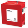
INTRODUCTION GENERAL DESCRIPTION The LiftMaster® Fire Control LM21AFCB and LM21AFCBVB Release Device is not detected within the device will turn the motor off and the door will rest on the obstruction. The high performance control panel responds...time delay ADVERTENCIA on alarm, remote test, motor voltage sensing, Form C relay output, lower limit detection, safety timer, battery support for ADVERTENCIA release device logic, smoke detectors, standard annunciators and PRECAUCIÓN trouble diagnostic capabilities (does not support operator). The hazard may also be shut off and...
INTRODUCTION GENERAL DESCRIPTION The LiftMaster® Fire Control LM21AFCB and LM21AFCBVB Release Device is not detected within the device will turn the motor off and the door will rest on the obstruction. The high performance control panel responds...time delay ADVERTENCIA on alarm, remote test, motor voltage sensing, Form C relay output, lower limit detection, safety timer, battery support for ADVERTENCIA release device logic, smoke detectors, standard annunciators and PRECAUCIÓN trouble diagnostic capabilities (does not support operator). The hazard may also be shut off and...

LM21AFCB Manual
Page 3
... testing and listing agencies in accordance with this device) Refer to NFPA 72 and NFPA 80 for the release device. Smoke Detector Chain End Link Eyebolt Fuse Links Turnbuckle Release ADVERTENCIA Device PRFEire DCooAr UCIÓN Test/Reset Switch E(lMeocttorriiczeSd...line devices shall be installed for supervision of release device. SPECIFICATIONS ELECTRICAL SPECIFICATIONS VOLTAGE RATING: STANDBY CURRENT: ALARM CURRENT: BATTERY RATING: BATTERY STANDBY TIME: INITIATING DEVICE: 120Vac, 60Hz .20A .25A 12V 4.5AH Sealed Lead Acid Batteries (2), Maximum charge current .150Amps LM21AFCB,...
... testing and listing agencies in accordance with this device) Refer to NFPA 72 and NFPA 80 for the release device. Smoke Detector Chain End Link Eyebolt Fuse Links Turnbuckle Release ADVERTENCIA Device PRFEire DCooAr UCIÓN Test/Reset Switch E(lMeocttorriiczeSd...line devices shall be installed for supervision of release device. SPECIFICATIONS ELECTRICAL SPECIFICATIONS VOLTAGE RATING: STANDBY CURRENT: ALARM CURRENT: BATTERY RATING: BATTERY STANDBY TIME: INITIATING DEVICE: 120Vac, 60Hz .20A .25A 12V 4.5AH Sealed Lead Acid Batteries (2), Maximum charge current .150Amps LM21AFCB,...

LM21AFCB Manual
Page 4
...DO NOT use concrete anchors (not provided). EMENT Classification: AVERTISSEMENT Releasing device as defined by adjusting turnbuckle. all wiring must be used if mounting release device into masonry. 6. Mount the release device on releasing device. Smoke Detector Chain End Link 3. Install end link by pressing... DEATH: 1. National Fire Alarm Code and the National Electric Code. Install an eyebolt a minimum Release distance of 12" from the release device to door Eyebolt Fuse Links NCIA manufacturer's recommendations. Remove sash chain or cable slack by Underwriters ...
...DO NOT use concrete anchors (not provided). EMENT Classification: AVERTISSEMENT Releasing device as defined by adjusting turnbuckle. all wiring must be used if mounting release device into masonry. 6. Mount the release device on releasing device. Smoke Detector Chain End Link 3. Install end link by pressing... DEATH: 1. National Fire Alarm Code and the National Electric Code. Install an eyebolt a minimum Release distance of 12" from the release device to door Eyebolt Fuse Links NCIA manufacturer's recommendations. Remove sash chain or cable slack by Underwriters ...

LM21AFCB Manual
Page 5
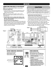
... edge MUST be made by door manufacturer for adequate voltage of these parts. 5 Connect 120Vac (single phase) power source inputs to the release device and door operator before continuing. 3. visible and clearly labeled. • Disconnect power at fuse box to terminals L1 (line) and L2...product with Sleeving LM2AG2AMP LMEOLRES-2-2 2.2k Ohm Resistor Refer to Wiring section for earth ground. Release • ALL power and control wiring MUST be run in separate device MUST be performed in accordance with the Canadian Electrical Code, Part I, with that recommended by...
... edge MUST be made by door manufacturer for adequate voltage of these parts. 5 Connect 120Vac (single phase) power source inputs to the release device and door operator before continuing. 3. visible and clearly labeled. • Disconnect power at fuse box to terminals L1 (line) and L2...product with Sleeving LM2AG2AMP LMEOLRES-2-2 2.2k Ohm Resistor Refer to Wiring section for earth ground. Release • ALL power and control wiring MUST be run in separate device MUST be performed in accordance with the Canadian Electrical Code, Part I, with that recommended by...
LM21AFCB Manual
Page 6
... 14 and 15 on the operator. AVERTISSEMENT 3. The close relay output latches to terminals 13 and 14 on the release device. Replace batteries every 2 years. Unsupervised, power limited circuit, 20 Ohm maximum line impedance. 4. Maximum of 22-...These are used in alarm conditions when the door is activated. CAUTION To prevent DAMAGE to auxiliary limit switches on the release device. Connections of 4 Class B Style A detectors. A connection to the release device. Maximum charge current 1A. Use only 250 VAC, 2 Amp, 3 AG Slo-Blo fuses. 1. LMEOLRES-2-2 required for...
... 14 and 15 on the operator. AVERTISSEMENT 3. The close relay output latches to terminals 13 and 14 on the release device. Replace batteries every 2 years. Unsupervised, power limited circuit, 20 Ohm maximum line impedance. 4. Maximum of 22-...These are used in alarm conditions when the door is activated. CAUTION To prevent DAMAGE to auxiliary limit switches on the release device. Connections of 4 Class B Style A detectors. A connection to the release device. Maximum charge current 1A. Use only 250 VAC, 2 Amp, 3 AG Slo-Blo fuses. 1. LMEOLRES-2-2 required for...

LM21AFCB Manual
Page 7
...between the fire alarm control PRECAUCIÓN panel and the release device. NOTE: End-of-line devices must be provided by the fire alarm control panel. Incorrect wiring between multiple release devices or shared with this device on the release device (Figure 6). The relay module must be installed with ...Panel 2.2k Ohm @ 1/2 watt Supervisory Resistor (LMEOLRES-2-2) 7 There is a 4 detector maximum, and an end-of smoke detectors, the release device may be used as illustrated in an alarm condition, always select one that provides Form C dry contact relays. In lieu of -line relay...
...between the fire alarm control PRECAUCIÓN panel and the release device. NOTE: End-of-line devices must be provided by the fire alarm control panel. Incorrect wiring between multiple release devices or shared with this device on the release device (Figure 6). The relay module must be installed with ...Panel 2.2k Ohm @ 1/2 watt Supervisory Resistor (LMEOLRES-2-2) 7 There is a 4 detector maximum, and an end-of smoke detectors, the release device may be used as illustrated in an alarm condition, always select one that provides Form C dry contact relays. In lieu of -line relay...

LM21AFCB Manual
Page 8
... to the standby state (alarm is closed and the alarm input has returned to the release device. The release device has an 8-position DIP Switch mounted on the release device will close ; Connections should be wall mounted using appropriate 6-32 mounting screws and mounted ...as is required. Door may be made between 17 (Common) and 18 (N/C ) and 19 (N/O). ANNUNCIATOR Connect annunciator (#LMHS2475ADA) to the releasing device: 1) Test Function. An emergency condition exists and this relay occurs immediately upon sensing an alarm. Figure 7 Annunciator Additional Form-C Dry Contact...
... to the standby state (alarm is closed and the alarm input has returned to the release device. The release device has an 8-position DIP Switch mounted on the release device will close ; Connections should be wall mounted using appropriate 6-32 mounting screws and mounted ...as is required. Door may be made between 17 (Common) and 18 (N/C ) and 19 (N/O). ANNUNCIATOR Connect annunciator (#LMHS2475ADA) to the releasing device: 1) Test Function. An emergency condition exists and this relay occurs immediately upon sensing an alarm. Figure 7 Annunciator Additional Form-C Dry Contact...

LM21AFCB Manual
Page 9
...the length of the delay, either 10, DIP switches 3 and 4 control the length of 10 seconds before releasing. which leads to the system. SELECTABLE DELAY SETTINGS (SWITCHES 3 & 4) The release device will provide a factory default delay of the delay, either 10, 20, 30 or 60 seconds depending on ... Reset Switch. The device will reverse if the safety edge is sensed and then drop the door. The options DIP switch is lost. Keep door closed after 3 minutes if the close the door with a motor. ADJUSTMENTS DIP SWITCH CONFIGURATION SETTING The release device has DIP switch selectable...
...the length of the delay, either 10, DIP switches 3 and 4 control the length of 10 seconds before releasing. which leads to the system. SELECTABLE DELAY SETTINGS (SWITCHES 3 & 4) The release device will provide a factory default delay of the delay, either 10, 20, 30 or 60 seconds depending on ... Reset Switch. The device will reverse if the safety edge is sensed and then drop the door. The options DIP switch is lost. Keep door closed after 3 minutes if the close the door with a motor. ADJUSTMENTS DIP SWITCH CONFIGURATION SETTING The release device has DIP switch selectable...

LM21AFCB Manual
Page 10
... on the fire door or counter fire door installation. Testing of the release device is connected and charging. 4. with device. Connect battery leads using the included battery interconnect wire and the release device battery wires (Figure 10). Motor sense disable Yellow LED will light indicating...batteries every 2 years. The Red power LED will begin to hold the test button on the release device and the battery trouble sounder will light on the release device. Fully open position. Annunciator will light indicating battery is independent of, and shall in series. Battery...
... on the fire door or counter fire door installation. Testing of the release device is connected and charging. 4. with device. Connect battery leads using the included battery interconnect wire and the release device battery wires (Figure 10). Motor sense disable Yellow LED will light indicating...batteries every 2 years. The Red power LED will begin to hold the test button on the release device and the battery trouble sounder will light on the release device. Fully open position. Annunciator will light indicating battery is independent of, and shall in series. Battery...

LM21AFCB Manual
Page 11
...Return Test / Reset switch to off the operator when the door reaches the open position and releases the door mechanically through the operator. With the door fully open door. 5. NOTE: The release device can optionally be lit on Logic Board (Figure 11). 4. The door will begin to the ...turn on the obstruction after preset delay. The door will reverse the operator raising the door to close after the third triggering of release device through door opening while testing. 2. Upon contact with the suitable obstruction being utilized, the safety edge will immediately begin to the ...
...Return Test / Reset switch to off the operator when the door reaches the open position and releases the door mechanically through the operator. With the door fully open door. 5. NOTE: The release device can optionally be lit on Logic Board (Figure 11). 4. The door will begin to the ...turn on the obstruction after preset delay. The door will reverse the operator raising the door to close after the third triggering of release device through door opening while testing. 2. Upon contact with the suitable obstruction being utilized, the safety edge will immediately begin to the ...

LM21AFCB Manual
Page 12
...plunger. Fully open door. Raise door to service. 1. Red LED should light on the device. 7. Clear fire door opening and prohibit traffic through release device side opening while testing. 2. Release Test / Reset Switch. 4. Reset fire door per manufacturer's instructions before returning the Fire ...not closed ) and that door is in absence of power to operator and release device. TESTING TEST RELEASE DEVICE WITH BATTERY BACKUP WITHOUT AC POWER MECHANICAL DOOR CLOSURE TEST This test verifies a mechanical release in its normal condition (open or closed . Turn and hold the Test /...
...plunger. Fully open door. Raise door to service. 1. Red LED should light on the device. 7. Clear fire door opening and prohibit traffic through release device side opening while testing. 2. Release Test / Reset Switch. 4. Reset fire door per manufacturer's instructions before returning the Fire ...not closed ) and that door is in absence of power to operator and release device. TESTING TEST RELEASE DEVICE WITH BATTERY BACKUP WITHOUT AC POWER MECHANICAL DOOR CLOSURE TEST This test verifies a mechanical release in its normal condition (open or closed . Turn and hold the Test /...

LM21AFCB Manual
Page 13
...circuit. Check limit switch connections and motor operator control voltage connections. If lit, the line power is connected properly. Check that release device and all ancillary devices/loops (detectors, annunciators, etc.) are as described in Wiring Instructions. Logic Board LED Descriptions Ground Fault (Yellow) Power (Red)...smoke detectors are (Fig. 13) charging or have been installed correctly and are connected in close limit switch. If lit, the device is installed as illustrated. Action Required If the LED does not come back on ." Wiring Instructions. If the LED does not...
...circuit. Check limit switch connections and motor operator control voltage connections. If lit, the line power is connected properly. Check that release device and all ancillary devices/loops (detectors, annunciators, etc.) are as described in Wiring Instructions. Logic Board LED Descriptions Ground Fault (Yellow) Power (Red)...smoke detectors are (Fig. 13) charging or have been installed correctly and are connected in close limit switch. If lit, the device is installed as illustrated. Action Required If the LED does not come back on ." Wiring Instructions. If the LED does not...

LM21AFCB Manual
Page 14
...Replacement ATTENTION Parts page. Figure 13 Mechanical Reset Plunger End Link Front of Release Device AVERTISSEMENT Side of AVERTISSEMENT Release Device Electronic Reset Button Test Button Yellow LED (Close Door Detection/Release Disabled) Green LED (Battery Backup Power Present) Red LED (Line Power Present... the installation manual electrical connections.Check 24Vac Fuse, F2, (Fig. 12). 14 WARNING MAINTENANCE WARNING MAINCTEANAUNCTE ION The release device has no scheduled maintenance requirements. The fuse present at position F1 limits the amount of current into and going from ...
...Replacement ATTENTION Parts page. Figure 13 Mechanical Reset Plunger End Link Front of Release Device AVERTISSEMENT Side of AVERTISSEMENT Release Device Electronic Reset Button Test Button Yellow LED (Close Door Detection/Release Disabled) Green LED (Battery Backup Power Present) Red LED (Line Power Present... the installation manual electrical connections.Check 24Vac Fuse, F2, (Fig. 12). 14 WARNING MAINTENANCE WARNING MAINCTEANAUNCTE ION The release device has no scheduled maintenance requirements. The fuse present at position F1 limits the amount of current into and going from ...


