LM21AFCB Manual
Page 1
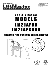
The Chamberlain Group, Inc. 845 Larch Avenue Elmhurst, Illinois 60126-1196 www.liftmaster.com OWNER'S MANUAL MODELS LM21AFCB LM21AFCBVB ADVANCE FIRE CONTROL RELEASE DEVICE FM APPROVED
The Chamberlain Group, Inc. 845 Larch Avenue Elmhurst, Illinois 60126-1196 www.liftmaster.com OWNER'S MANUAL MODELS LM21AFCB LM21AFCBVB ADVANCE FIRE CONTROL RELEASE DEVICE FM APPROVED

LM21AFCB Manual
Page 2
... Operator 6 Connections of Initiating Devices and Accessories 7 Optional Connections 8 ADJUSTMENTS DIP Switch Configuration Setting 9 Selectable Delay Settings (Switches 3 & 4 9 TESTING Test Release Device and Door Operator 10-11 AVERTISSEMENT Test Release Device With Battery Backup Without AC Power . .12 TROUBLESHOOTING Diagnostic LEDs 13 ATTENTION MAINTENANCE Maintenance 14 Enclosure Mounted LEDs Status Indicators 14 ACCESSORIES AND REPAIR PARTS 15 APPENDIX 16 WARNING Mechanical CAUTION WARNING WElAecRtricNalING CAWUATRIONNING When you see this manual and follow all releasing...
... Operator 6 Connections of Initiating Devices and Accessories 7 Optional Connections 8 ADJUSTMENTS DIP Switch Configuration Setting 9 Selectable Delay Settings (Switches 3 & 4 9 TESTING Test Release Device and Door Operator 10-11 AVERTISSEMENT Test Release Device With Battery Backup Without AC Power . .12 TROUBLESHOOTING Diagnostic LEDs 13 ATTENTION MAINTENANCE Maintenance 14 Enclosure Mounted LEDs Status Indicators 14 ACCESSORIES AND REPAIR PARTS 15 APPENDIX 16 WARNING Mechanical CAUTION WARNING WElAecRtricNalING CAWUATRIONNING When you see this manual and follow all releasing...

LM21AFCB Manual
Page 3
... installed for supervision of this device without an electric safety edge. • DO NOT use of electrical power to the door manufacturer's recommendations for use this product with specific door being utilized. Use only hardware approved or recognized by means of a UL/ULC listed end-of this device) Refer to , all appendices and amendments and the requirements of release device. Smoke Detector Chain End Link Eyebolt Fuse Links...
... installed for supervision of this device without an electric safety edge. • DO NOT use of electrical power to the door manufacturer's recommendations for use this product with specific door being utilized. Use only hardware approved or recognized by means of a UL/ULC listed end-of this device) Refer to , all appendices and amendments and the requirements of release device. Smoke Detector Chain End Link Eyebolt Fuse Links...

LM21AFCB Manual
Page 4
... AND FOLLOW ALL INSTALLATION WARNINGS AND INSTRUCTIONS. 2. NEVER connect release device to power source until instructed to door types. EMENT Classification: AVERTISSEMENT Releasing device as defined by adjusting turnbuckle. Concrete anchors MUST be performed in accordance with the most current version of end link. Push end link completely in masonry, use this device on a motorized door without fuse links installed. 5. Mechanical Reset Plunger End Link MOUNT THE RELEASE DEVICE Installation procedures vary according...
... AND FOLLOW ALL INSTALLATION WARNINGS AND INSTRUCTIONS. 2. NEVER connect release device to power source until instructed to door types. EMENT Classification: AVERTISSEMENT Releasing device as defined by adjusting turnbuckle. Concrete anchors MUST be performed in accordance with the most current version of end link. Push end link completely in masonry, use this device on a motorized door without fuse links installed. 5. Mechanical Reset Plunger End Link MOUNT THE RELEASE DEVICE Installation procedures vary according...

LM21AFCB Manual
Page 5
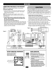
... fuse box BEFORE proceeding. NCIAWIRE ROUTING ADVERTENCIA Mechanical Reset Plunger L1L2 Ground Power Strip Option DIP Switch ÓN ADVERTENCIA PARTS KIT High Voltage Wiring Low Voltage Wiring Voice Board Wiring Annunciator Wiring with that recommended by a qualified protected. In addition, ALL installations subject to Canadian standards shall be performed in accordance with the Canadian Electrical Code, Part I, with the installation. ON POWER WIRING CONNECTIONS AVERTISSEMENT This device is used on ALL motorized doors...
... fuse box BEFORE proceeding. NCIAWIRE ROUTING ADVERTENCIA Mechanical Reset Plunger L1L2 Ground Power Strip Option DIP Switch ÓN ADVERTENCIA PARTS KIT High Voltage Wiring Low Voltage Wiring Voice Board Wiring Annunciator Wiring with that recommended by a qualified protected. In addition, ALL installations subject to Canadian standards shall be performed in accordance with the Canadian Electrical Code, Part I, with the installation. ON POWER WIRING CONNECTIONS AVERTISSEMENT This device is used on ALL motorized doors...
LM21AFCB Manual
Page 6
... a motor control or ANY other voltage through the operator after the factory set delay. AVERTISSEMENT 3. Connect wires from the release device to the door operator terminals that are required and must be used for 3-button station (for 3-cycle obstruction count feature. Voice Board Model Only + Speaker - Supervised, power limited circuit, 20 Ohm maximum line impedance. 2. Supervised, non-power limited circuit. 20 Ohm maximum line impedance. Connections of the auxiliary limit switch to Red...
... a motor control or ANY other voltage through the operator after the factory set delay. AVERTISSEMENT 3. Connect wires from the release device to the door operator terminals that are required and must be used for 3-button station (for 3-cycle obstruction count feature. Voice Board Model Only + Speaker - Supervised, power limited circuit, 20 Ohm maximum line impedance. 2. Supervised, non-power limited circuit. 20 Ohm maximum line impedance. Connections of the auxiliary limit switch to Red...

LM21AFCB Manual
Page 7
... using 4-wire smoke detectors with this device on the release device (Figure 6). Figure 3 On Circuit Board 2.2k Ohm @ 1/2 watt Supervisory Resistor (LMEOLRES-2-2) - Incorrect wiring between the fire alarm control PRECAUCIÓN panel and the release device. Connect wiring from N/O 4-Wire initiating device loop to activate the release device in figure 4 or 5. (Do not share alarm loop with other alarm circuits.) 2. The relay module must be installed for supervision of electrical power...
... using 4-wire smoke detectors with this device on the release device (Figure 6). Figure 3 On Circuit Board 2.2k Ohm @ 1/2 watt Supervisory Resistor (LMEOLRES-2-2) - Incorrect wiring between the fire alarm control PRECAUCIÓN panel and the release device. Connect wiring from N/O 4-Wire initiating device loop to activate the release device in figure 4 or 5. (Do not share alarm loop with other alarm circuits.) 2. The relay module must be installed for supervision of electrical power...

LM21AFCB Manual
Page 8
... must be secured with a minimum 2" depth using a single gang junction box at position #8 permits selection of wire run within the same room as illustrated (Figure 7). DC .75A Maximum Current During Alarm 2.2k Ohm @ 1/2 watt Supervisory Resistor (LMEOLRES-2-2) Figure 8 ADVERTENCIA Volume Control CCW for details. 2) Alarm Resetting. PRECAUCIÓN Wire to speaker strobes (Model LMPSTR2475ADA). WIRING WARNING OPTIONAL CONNECTIONS WALL MOUNTED REMOTE TEST / RESET SWITCH The provided...
... must be secured with a minimum 2" depth using a single gang junction box at position #8 permits selection of wire run within the same room as illustrated (Figure 7). DC .75A Maximum Current During Alarm 2.2k Ohm @ 1/2 watt Supervisory Resistor (LMEOLRES-2-2) Figure 8 ADVERTENCIA Volume Control CCW for details. 2) Alarm Resetting. PRECAUCIÓN Wire to speaker strobes (Model LMPSTR2475ADA). WIRING WARNING OPTIONAL CONNECTIONS WALL MOUNTED REMOTE TEST / RESET SWITCH The provided...

LM21AFCB Manual
Page 9
DIP Switch 1 2 3 4 5 6 7 8 Switch "ON" Switch "OFF" Motorized door. to close the door but will reverse if the safety edge is triggered. Stop on the logic board. If a motorized door is used, the device will attempt to close the door with a motor. The device will attempt to close it is sensed the third time. Will drop the door after sensing an obstruction three times. SELECTABLE DELAY SETTINGS (SWITCHES 3 & 4) The release device will provide a factory default delay of...
DIP Switch 1 2 3 4 5 6 7 8 Switch "ON" Switch "OFF" Motorized door. to close the door but will reverse if the safety edge is triggered. Stop on the logic board. If a motorized door is used, the device will attempt to close the door with a motor. The device will attempt to close it is sensed the third time. Will drop the door after sensing an obstruction three times. SELECTABLE DELAY SETTINGS (SWITCHES 3 & 4) The release device will provide a factory default delay of...

LM21AFCB Manual
Page 10
... door opening and prohibit traffic through door opening while testing. • DO NOT install this device on power to assure proper operation of , and shall in series. with device. Turn on a motorized door without an electric safety edge. • Test every 90 days to motor. Motor sense disable Yellow LED will light indicating battery is complete. 8. Annunciator will begin to close limit. 7. Depress "Open" button on the fire door or counter fire door installation. Battery Interconnect Wire Battery 1 Red...
... door opening and prohibit traffic through door opening while testing. • DO NOT install this device on power to assure proper operation of , and shall in series. with device. Turn on a motorized door without an electric safety edge. • Test every 90 days to motor. Motor sense disable Yellow LED will light indicating battery is complete. 8. Annunciator will begin to close limit. 7. Depress "Open" button on the fire door or counter fire door installation. Battery Interconnect Wire Battery 1 Red...

LM21AFCB Manual
Page 11
... triggering of the safety edge (see DIP Switch Configuration Setting. 11 The annunciator will turn off position. 3. Release test button. Reset release device by pushing in direction of the door. 2. Insert key into wall mounted Test / Reset switch, turn on door control to silence the annunciator. Annunciator will turn key and hold the test button of the closing door, the door will fully close and the motor will close through door opening and release reset plunger latching the end link. 7. If no...
... triggering of the safety edge (see DIP Switch Configuration Setting. 11 The annunciator will turn off position. 3. Release test button. Reset release device by pushing in direction of the door. 2. Insert key into wall mounted Test / Reset switch, turn on door control to silence the annunciator. Annunciator will turn key and hold the test button of the closing door, the door will fully close and the motor will close through door opening and release reset plunger latching the end link. 7. If no...

LM21AFCB Manual
Page 12
... "Reset" button on release device. Turn and hold the Test / Reset Switch or depress and hold "Test" button on the device. 7. Fully insert end link through door opening and release mechanical reset plunger to the Configuration Settings) device will release door. Annunciator will release (close). 3. Red LED should light on the release device indicating power has been restored 6. The device is restored to the operator. TESTING TEST RELEASE DEVICE WITH BATTERY BACKUP WITHOUT AC POWER MECHANICAL DOOR CLOSURE...
... "Reset" button on release device. Turn and hold the Test / Reset Switch or depress and hold "Test" button on the device. 7. Fully insert end link through door opening and release mechanical reset plunger to the Configuration Settings) device will release door. Annunciator will release (close). 3. Red LED should light on the release device indicating power has been restored 6. The device is restored to the operator. TESTING TEST RELEASE DEVICE WITH BATTERY BACKUP WITHOUT AC POWER MECHANICAL DOOR CLOSURE...

LM21AFCB Manual
Page 13
... that auxiliary limit connections are made as illustrated. Check limit switch connections and motor operator control voltage connections. If lit, 2.2k Ohm resistor is not installed on the Open limit, input is installed as described in a state where it will not release the door. If lit, the line power is in circuit. Press the "Reset" button to earth ground exists. Note that LED lights when system is connected and switched "on the Close limit, check...
... that auxiliary limit connections are made as illustrated. Check limit switch connections and motor operator control voltage connections. If lit, 2.2k Ohm resistor is not installed on the Open limit, input is installed as described in a state where it will not release the door. If lit, the line power is in circuit. Press the "Reset" button to earth ground exists. Note that LED lights when system is connected and switched "on the Close limit, check...

LM21AFCB Manual
Page 14
...of the power supply circuit board. If the LED does not light when power is connected as described in accordance with the fuses installed and replacement fuses (2) are required for proper operation and protection of AVERTISSEMENT Release Device Electronic Reset Button Test Button Yellow LED (Close Door Detection/Release Disabled) Green LED (Battery Backup Power Present) Red LED (Line Power Present) ENCLOSURE MOUNTED LEDS STATUS INDICATORS LED Label LED Color Description Action Required ADVERTENCIA Battery Green If the Green LED is lit, then the battery is connected ADVERTENCIA...
...of the power supply circuit board. If the LED does not light when power is connected as described in accordance with the fuses installed and replacement fuses (2) are required for proper operation and protection of AVERTISSEMENT Release Device Electronic Reset Button Test Button Yellow LED (Close Door Detection/Release Disabled) Green LED (Battery Backup Power Present) Red LED (Line Power Present) ENCLOSURE MOUNTED LEDS STATUS INDICATORS LED Label LED Color Description Action Required ADVERTENCIA Battery Green If the Green LED is lit, then the battery is connected ADVERTENCIA...
LM21AFCB Manual
Page 15
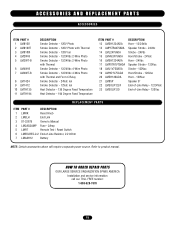
... 8" End-of-Line Relay - 12/24Vdc End-of-Line Relay - 120Vac REPLACEMENT PARTS ITEM PART # DESCRIPTION 1 LMRK Reset Knob 2 LMELH End Link 3 01-32675 Owner's Manual 4 LM2AG2AMP Fuse - 2Amp 5 LMRT Remote Test / Reset Switch 6 LMEOLRES-2-2 End-of-Line Resistor, 2.2 kOhm 7 LM4AH12 Battery NOTE: Certain accessories above will require a separate power source. HOW TO ORDER REPAIR PARTS OUR LARGE SERVICE ORGANIZATION SPANS AMERICA Installation and service information call our TOLL FREE number: 1-888-528...
... 8" End-of-Line Relay - 12/24Vdc End-of-Line Relay - 120Vac REPLACEMENT PARTS ITEM PART # DESCRIPTION 1 LMRK Reset Knob 2 LMELH End Link 3 01-32675 Owner's Manual 4 LM2AG2AMP Fuse - 2Amp 5 LMRT Remote Test / Reset Switch 6 LMEOLRES-2-2 End-of-Line Resistor, 2.2 kOhm 7 LM4AH12 Battery NOTE: Certain accessories above will require a separate power source. HOW TO ORDER REPAIR PARTS OUR LARGE SERVICE ORGANIZATION SPANS AMERICA Installation and service information call our TOLL FREE number: 1-888-528...

LM21AFCB Manual
Page 16
... SENSOR MODEL NO. EOLR-1 PAM-1 LIFTMASTER NO. Refer to product manual. 01-32675D Issue Date 2/11/2008 © 2008, The Chamberlain Group, Inc. LMTH135 LMTH194 DESCRIPTION 135 Degree Fixed Temperature 194 Degree Fixed Temperature MODEL NO. APPENDIX ACCESSORY COMPATIBILITY GUIDE MODEL NO. LMEOLRES-2-2 NOTE: Certain accessories above will require a separate power source. LM2W-B LM2WT-B LM4W-B LM4WT-B LM1424 SMOKE DETECTORS DESCRIPTION 24Vdc 2-Wire Photo SYSTEM SENSOR MODEL...
... SENSOR MODEL NO. EOLR-1 PAM-1 LIFTMASTER NO. Refer to product manual. 01-32675D Issue Date 2/11/2008 © 2008, The Chamberlain Group, Inc. LMTH135 LMTH194 DESCRIPTION 135 Degree Fixed Temperature 194 Degree Fixed Temperature MODEL NO. APPENDIX ACCESSORY COMPATIBILITY GUIDE MODEL NO. LMEOLRES-2-2 NOTE: Certain accessories above will require a separate power source. LM2W-B LM2WT-B LM4W-B LM4WT-B LM1424 SMOKE DETECTORS DESCRIPTION 24Vdc 2-Wire Photo SYSTEM SENSOR MODEL...


