
LA500DC Sell Sheet Manual
Page 2
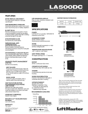
...and standby time on battery backup. **Power efficient LiftMaster design saves power when running on /off the interrupt loop. RECOMMENDED CAPACITIES HOMELINK® COMPATIBLE Version 4 and higher. Your installer will pause when closing as necessary to ensure primary .... © 2014 LiftMaster All Rights Reserved 845 Larch Ave., Elmhurst, IL 60126 LiftMaster.com LMGTCALA5D 6/14 . . . . . . . . LA500DC RESIDENTIAL/LIGHT COMMERCIAL DC LINEAR ACTUATOR FEATURES KEYED MANUAL DISCONNECT Provides simple method to -read, simplifies installation and troubleshooting. LED DIAGNOSTIC...
...and standby time on battery backup. **Power efficient LiftMaster design saves power when running on /off the interrupt loop. RECOMMENDED CAPACITIES HOMELINK® COMPATIBLE Version 4 and higher. Your installer will pause when closing as necessary to ensure primary .... © 2014 LiftMaster All Rights Reserved 845 Larch Ave., Elmhurst, IL 60126 LiftMaster.com LMGTCALA5D 6/14 . . . . . . . . LA500DC RESIDENTIAL/LIGHT COMMERCIAL DC LINEAR ACTUATOR FEATURES KEYED MANUAL DISCONNECT Provides simple method to -read, simplifies installation and troubleshooting. LED DIAGNOSTIC...
LA500DC Owner's Manual
Page 3
...TO THE CONTROL BOARD 14 DUAL GATES ONLY 15 INSTALL ENTRAPMENT PROTECTION 18 POWER WIRING 20 FINISH INSTALL 22 ADJUSTMENT 22 LIMIT AND FORCE ADJUSTMENT 22 OBSTRUCTION TEST 24 PROGRAMMING 25 REMOTE CONTROLS (NOT PROVIDED 25 LIFTMASTER INTERNET GATEWAY (NOT PROVIDED 26 ERASE ALL CODES ...SAFETY INFORMATION 36 MAINTENANCE CHART 36 BATTERIES 36 TROUBLESHOOTING 37 ERROR CODES 37 CONTROL BOARD LEDS 40 TROUBLESHOOTING CHART 41 APPENDIX 44 INSTALLATION TYPES 44 POSITION THE BRACKETS 44 SOLAR PANEL(S 45 LIMIT SETUP WITH A REMOTE CONTROL 50 SAMS WIRING WITH RELAYS NOT...
...TO THE CONTROL BOARD 14 DUAL GATES ONLY 15 INSTALL ENTRAPMENT PROTECTION 18 POWER WIRING 20 FINISH INSTALL 22 ADJUSTMENT 22 LIMIT AND FORCE ADJUSTMENT 22 OBSTRUCTION TEST 24 PROGRAMMING 25 REMOTE CONTROLS (NOT PROVIDED 25 LIFTMASTER INTERNET GATEWAY (NOT PROVIDED 26 ERASE ALL CODES ...SAFETY INFORMATION 36 MAINTENANCE CHART 36 BATTERIES 36 TROUBLESHOOTING 37 ERROR CODES 37 CONTROL BOARD LEDS 40 TROUBLESHOOTING CHART 41 APPENDIX 44 INSTALLATION TYPES 44 POSITION THE BRACKETS 44 SOLAR PANEL(S 45 LIMIT SETUP WITH A REMOTE CONTROL 50 SAMS WIRING WITH RELAYS NOT...

LA500DC Owner's Manual
Page 4
... or DEATH. • Use the emergency release ONLY when the gate is in accordance with a residence of a single device to install additional entrapment protection devices in each entrapment zone. Read the owner's manual. Pedestrians MUST use in a commercial location or building such ...prevented via supervision by or intended to adjust and retest the gate operator properly can increase the risk of device shall not be installed with gate controls. Failure to service the general public. CLASS III - INDUSTRIAL/LIMITED ACCESS III VEHICULAR GATE OPERATOR A vehicular ...
... or DEATH. • Use the emergency release ONLY when the gate is in accordance with a residence of a single device to install additional entrapment protection devices in each entrapment zone. Read the owner's manual. Pedestrians MUST use in a commercial location or building such ...prevented via supervision by or intended to adjust and retest the gate operator properly can increase the risk of device shall not be installed with gate controls. Failure to service the general public. CLASS III - INDUSTRIAL/LIMITED ACCESS III VEHICULAR GATE OPERATOR A vehicular ...

LA500DC Owner's Manual
Page 5
... operator is prevented from any location in the open into every design. The pedestrian access opening . Activation of application. See Install Entrapment Protection section. c. A wireless device shall function under , around or through the openings anywhere in the gate, and ...incorporated into public access areas. 7. Specific safety features include: • Edges Sensors (contact) • Guards for an individual application. 2. Install the gate operator only when: a. b. All openings of a horizontal slide gate are comprised of the gate. 9. All exposed pinch points...
... operator is prevented from any location in the open into every design. The pedestrian access opening . Activation of application. See Install Entrapment Protection section. c. A wireless device shall function under , around or through the openings anywhere in the gate, and ...incorporated into public access areas. 7. Specific safety features include: • Edges Sensors (contact) • Guards for an individual application. 2. Install the gate operator only when: a. b. All openings of a horizontal slide gate are comprised of the gate. 9. All exposed pinch points...
LA500DC Owner's Manual
Page 6
...as a wall, pillar or column, and a swing gate when in the open and fully closed positions. The pedestrian gate shall be installed in a location such that a pedestrian shall not come in accordance with ASTM F2200: Standard Specification for Automated Vehicular Gate Construction. SPECIFIC ... existing gate latch shall be disabled when a manually operated gate is retrofitted with a powered gate operator. 1.6 A gate latch shall not be installed on an automatically operated gate. 1.7 Protrusions shall not be permitted on any back frame or counterbalance portion of the gate. 3.1.3 A gap,...
...as a wall, pillar or column, and a swing gate when in the open and fully closed positions. The pedestrian gate shall be installed in a location such that a pedestrian shall not come in accordance with ASTM F2200: Standard Specification for Automated Vehicular Gate Construction. SPECIFIC ... existing gate latch shall be disabled when a manually operated gate is retrofitted with a powered gate operator. 1.6 A gate latch shall not be installed on an automatically operated gate. 1.7 Protrusions shall not be permitted on any back frame or counterbalance portion of the gate. 3.1.3 A gap,...

LA500DC Owner's Manual
Page 7
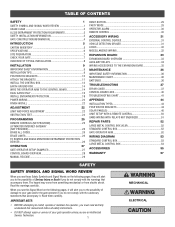
Large Metal Control Box for Solar Applications (Model XLSOLARCONTDC) Required for installations that require additional room in the control box (batteries not included). Requires two 33AH batteries, battery tray, and solar battery ...packet and hardware bag Gate Operator Post Bracket Gate Bracket Warning Signs (2) and Warranty Card Standard Control Box with Batteries 12 Vdc 7AH (2) MODEL LA500DCS ONLY Key (2) Key (2) Post Bracket Gate Bracket Junction Box Terminal Block Connector Gate Operator Watertight Connector (2) Extension Cable Connector OPTIONAL ACCESSORIES (ORDERED...
Large Metal Control Box for Solar Applications (Model XLSOLARCONTDC) Required for installations that require additional room in the control box (batteries not included). Requires two 33AH batteries, battery tray, and solar battery ...packet and hardware bag Gate Operator Post Bracket Gate Bracket Warning Signs (2) and Warranty Card Standard Control Box with Batteries 12 Vdc 7AH (2) MODEL LA500DCS ONLY Key (2) Key (2) Post Bracket Gate Bracket Junction Box Terminal Block Connector Gate Operator Watertight Connector (2) Extension Cable Connector OPTIONAL ACCESSORIES (ORDERED...

LA500DC Owner's Manual
Page 9
...underground utility locating companies. Loops are not required but are obstructing the gate path. Gate MUST swing freely and be constructed and installed according to ASTM F2200 standards (refer to specifications). Conduit must fit specifications of operator (refer to page 4). LOOPS Loops allow ...against any entrapment or safety conditions encountered in your gate application (refer to stay open when vehicles are recommended. TRENCH Trench and install conduit. Remove ANY/ALL wheels from the bottom of the gate. (Inside Property) GATE Gate must be supported entirely by its...
...underground utility locating companies. Loops are not required but are obstructing the gate path. Gate MUST swing freely and be constructed and installed according to ASTM F2200 standards (refer to specifications). Conduit must fit specifications of operator (refer to page 4). LOOPS Loops allow ...against any entrapment or safety conditions encountered in your gate application (refer to stay open when vehicles are recommended. TRENCH Trench and install conduit. Remove ANY/ALL wheels from the bottom of the gate. (Inside Property) GATE Gate must be supported entirely by its...

LA500DC Owner's Manual
Page 10
... Warning Sign Operator Edge Sensors NOTE: One or more information). All the illustrations on the following pages display a typical Left-Hand Gate installation with a pull-to the Appendix. Photoelectric Sensors Water Tight Conduit (Not provided) NOTE: Power and control wiring MUST be run in ...control wiring MUST be run in separate conduits. For Push-to-Open applications refer to -open bracket. INTRODUCTION OVERVIEW OF TYPICAL INSTALLATION Identify your installation type (refer to the Appendix in the back of the manual for more non-contact sensors shall be located where the risk...
... Warning Sign Operator Edge Sensors NOTE: One or more information). All the illustrations on the following pages display a typical Left-Hand Gate installation with a pull-to the Appendix. Photoelectric Sensors Water Tight Conduit (Not provided) NOTE: Power and control wiring MUST be run in ...control wiring MUST be run in separate conduits. For Push-to-Open applications refer to -open bracket. INTRODUCTION OVERVIEW OF TYPICAL INSTALLATION Identify your installation type (refer to the Appendix in the back of the manual for more non-contact sensors shall be located where the risk...
LA500DC Owner's Manual
Page 11
...with a rigid object. • To AVOID damaging gas, power or other control may travel limits) is not a chance of INJURY at any installation for strength. To prevent INJURY to pedestrians, a separate pedestrian access should be supplied, visible from a moving gate. • Locate entrapment protection ... anywhere the gate may also need adjustment. • After ANY adjustments are made, the safety reversal system MUST be located at all times. Install enclosed-style gate tracks and roller guards. • Place screen mesh 6 feet (1.8 m) high on any point during BOTH the open and...
...with a rigid object. • To AVOID damaging gas, power or other control may travel limits) is not a chance of INJURY at any installation for strength. To prevent INJURY to pedestrians, a separate pedestrian access should be supplied, visible from a moving gate. • Locate entrapment protection ... anywhere the gate may also need adjustment. • After ANY adjustments are made, the safety reversal system MUST be located at all times. Install enclosed-style gate tracks and roller guards. • Place screen mesh 6 feet (1.8 m) high on any point during BOTH the open and...

LA500DC Owner's Manual
Page 12
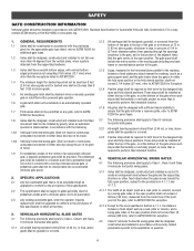
...(16.5 cm) Inside Property Opened Gate 11-1/4" minimum (28.6 cm) FIGURE 3 Gate Bracket Location 2-1/4" (6.4 cm) 10 Choose a vertical mounting location for a standard installation. Tack weld the gate bracket in this area is required. • While the gate is Push-to-Open, refer to the edge of the post...measure out dimension A (see chart) from the center of the hinge to the illustrations in an area that can withstand heavy forces. INSTALLATION STEP 1 POSITION THE BRACKETS If this mark (Figure 3). Remove the Miracle-One™ operator from the previous mark and center the ...
...(16.5 cm) Inside Property Opened Gate 11-1/4" minimum (28.6 cm) FIGURE 3 Gate Bracket Location 2-1/4" (6.4 cm) 10 Choose a vertical mounting location for a standard installation. Tack weld the gate bracket in this area is required. • While the gate is Push-to-Open, refer to the edge of the post...measure out dimension A (see chart) from the center of the hinge to the illustrations in an area that can withstand heavy forces. INSTALLATION STEP 1 POSITION THE BRACKETS If this mark (Figure 3). Remove the Miracle-One™ operator from the previous mark and center the ...

LA500DC Owner's Manual
Page 13
.... Tighten the nut until it reaches the bottom of the gate bracket, then turn the nut a half turn it 180 degrees counterclockwise. INSTALLATION STEP 2 ATTACH THE BRACKETS 1. Remove the operator from the gate. 4. Post Bracket Key Release Lever Gate Bracket For dual gate applications, repeat... the previous installation steps to move the trolley back and forth. NOTE: Brackets may be needed to install the second operator. 11 Make sure the trolley does not reach the fully open or fully ...
.... Tighten the nut until it reaches the bottom of the gate bracket, then turn the nut a half turn it 180 degrees counterclockwise. INSTALLATION STEP 2 ATTACH THE BRACKETS 1. Remove the operator from the gate. 4. Post Bracket Key Release Lever Gate Bracket For dual gate applications, repeat... the previous installation steps to move the trolley back and forth. NOTE: Brackets may be needed to install the second operator. 11 Make sure the trolley does not reach the fully open or fully ...

LA500DC Owner's Manual
Page 14
... CONTROL BOX For Large Metal Control Box installation, refer to the expansion board. Remove the screws and open the control box. 2. Wall or Column: Use the provided screws (4). Reinstall the expansion board and ... a screwdriver and hammer. 5. Select the mounting holes (according to ensure a watertight seal. B. Mount the control box as high as possible for a wall or column mount installation. 1. Remove the expansion board by removing the screws. 4. Make sure the U-bolts do not protrude more than 3/4 inch from the expansion board. 3. NOTE: The expansion...
... CONTROL BOX For Large Metal Control Box installation, refer to the expansion board. Remove the screws and open the control box. 2. Wall or Column: Use the provided screws (4). Reinstall the expansion board and ... a screwdriver and hammer. 5. Select the mounting holes (according to ensure a watertight seal. B. Mount the control box as high as possible for a wall or column mount installation. 1. Remove the expansion board by removing the screws. 4. Make sure the U-bolts do not protrude more than 3/4 inch from the expansion board. 3. NOTE: The expansion...

LA500DC Owner's Manual
Page 15
...have the electrical outlets or the expansion board shown in the images. Lift the door from the hinges and set aside until the installation is not recommended for best radio reception. Open the control box. TYPE AND SIZE Standard 3" Round Pipe Standard 4" Square Post Standard...knock out using a screwdriver and hammer. 3. Make sure the control box is complete. 2. INSTALLATION STEP 3 continued... Secure the control box to mounting surface with 'U' bolts (refer to chart). INSTALL THE CONTROL BOX LARGE METAL CONTROL BOX The control box MUST be mounted to a post with...
...have the electrical outlets or the expansion board shown in the images. Lift the door from the hinges and set aside until the installation is not recommended for best radio reception. Open the control box. TYPE AND SIZE Standard 3" Round Pipe Standard 4" Square Post Standard...knock out using a screwdriver and hammer. 3. Make sure the control box is complete. 2. INSTALLATION STEP 3 continued... Secure the control box to mounting surface with 'U' bolts (refer to chart). INSTALL THE CONTROL BOX LARGE METAL CONTROL BOX The control box MUST be mounted to a post with...

LA500DC Owner's Manual
Page 16
... cable wires to the connector according to the colored label on the control board as shown. 7. Plug the connector into the knockout. 4. INSTALLATION To reduce the risk of SEVERE INJURY or DEATH: • ANY maintenance to the operator or in separate conduit. Choose a knockout in ...the operator without consulting the wiring diagram. STEP 4 EARTH GROUND ROD Use the proper earth ground rod for your local area. If installing one operator, proceed to the following page. 14 (control board) Connector Operator Cable Watertight Connector Connector Nut Operator MUST be performed ...
... cable wires to the connector according to the colored label on the control board as shown. 7. Plug the connector into the knockout. 4. INSTALLATION To reduce the risk of SEVERE INJURY or DEATH: • ANY maintenance to the operator or in separate conduit. Choose a knockout in ...the operator without consulting the wiring diagram. STEP 4 EARTH GROUND ROD Use the proper earth ground rod for your local area. If installing one operator, proceed to the following page. 14 (control board) Connector Operator Cable Watertight Connector Connector Nut Operator MUST be performed ...

LA500DC Owner's Manual
Page 17
...5. Press and release the LEARN button again on the same control board. The yellow NETWORK LED will blink (operator will require the installation of two control boxes, one for 5 seconds. Wireless dual gates will beep) then turn off indicating successful deactivation. The green XMITTER... Press and release the LEARN button on the secondary control board. Follow the directions according to assign this operator as network secondary. INSTALLATION STEP 6 DUAL GATES ONLY There are set on the primary control board. 2. NOTE: We recommend that all accessories and board ...
...5. Press and release the LEARN button again on the same control board. The yellow NETWORK LED will blink (operator will require the installation of two control boxes, one for 5 seconds. Wireless dual gates will beep) then turn off indicating successful deactivation. The green XMITTER... Press and release the LEARN button on the secondary control board. Follow the directions according to assign this operator as network secondary. INSTALLATION STEP 6 DUAL GATES ONLY There are set on the primary control board. 2. NOTE: We recommend that all accessories and board ...

LA500DC Owner's Manual
Page 18
...the wires from extension cable and operator cable to bury the extension cable. DUAL GATES ONLY WIRED DUAL GATES INSTALLATION INSTALL A SECOND OPERATOR ARM Install a second operator arm by following installation steps 1-2. Trench across driveway to the terminal block connector as shown (like-colored wires must face each other...). 9. INSTALL THE EXTENSION CABLE AND JUNCTION BOX Before digging, contact local underground utility locating companies. 1. Route operator cable and...
...the wires from extension cable and operator cable to bury the extension cable. DUAL GATES ONLY WIRED DUAL GATES INSTALLATION INSTALL A SECOND OPERATOR ARM Install a second operator arm by following installation steps 1-2. Trench across driveway to the terminal block connector as shown (like-colored wires must face each other...). 9. INSTALL THE EXTENSION CABLE AND JUNCTION BOX Before digging, contact local underground utility locating companies. 1. Route operator cable and...

LA500DC Owner's Manual
Page 19
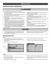
... connector (white to white, red to Gate 1 Connector on the same side as shown. 7. This would require one gate to be installed on Control Board. If there is called the Primary gate and needs to close second. OUTSIDE PROPERTY Primary Gate Primary Gate - This gate...) Primary Operator Secondary Operator SET THE BIPART DELAY (SINGLE CONTROL BOX) Occasionally in dual gate installations, one gate will need to the ON position. DUAL GATES ONLY WIRED DUAL GATES INSTALLATION (Control Board) WIRE THE SECONDARY OPERATOR ARM TO THE CONTROL BOARD 1. Insert the extension cable...
... connector (white to white, red to Gate 1 Connector on the same side as shown. 7. This would require one gate to be installed on Control Board. If there is called the Primary gate and needs to close second. OUTSIDE PROPERTY Primary Gate Primary Gate - This gate...) Primary Operator Secondary Operator SET THE BIPART DELAY (SINGLE CONTROL BOX) Occasionally in dual gate installations, one gate will need to the ON position. DUAL GATES ONLY WIRED DUAL GATES INSTALLATION (Control Board) WIRE THE SECONDARY OPERATOR ARM TO THE CONTROL BOARD 1. Insert the extension cable...

LA500DC Owner's Manual
Page 20
...and a stationary object. An entrapment zone is required. All gate operator systems REQUIRE two independent entrapment protection systems for Close Cycle 18 INSTALLATION To prevent SERIOUS INJURY or DEATH from the device it will not run. Monitored Photoelectric Sensors (Outside Property) (Inside Property) Sensors for... obstruction is less than 16" (40.6 cm) entrapment protection for EACH entrapment zone. The gate will stop . STEP 7 INSTALL ENTRAPMENT PROTECTION At least one or many entrapment zones. Your application may come near a moving , the gate will not be used.
...and a stationary object. An entrapment zone is required. All gate operator systems REQUIRE two independent entrapment protection systems for Close Cycle 18 INSTALLATION To prevent SERIOUS INJURY or DEATH from the device it will not run. Monitored Photoelectric Sensors (Outside Property) (Inside Property) Sensors for... obstruction is less than 16" (40.6 cm) entrapment protection for EACH entrapment zone. The gate will stop . STEP 7 INSTALL ENTRAPMENT PROTECTION At least one or many entrapment zones. Your application may come near a moving , the gate will not be used.

LA500DC Owner's Manual
Page 21
...the wiring diagram or the specific entrapment protection device manual for monitored devices, which include pulsed photoelectric sensors, resistive edge sensors, and pulsed edge sensors. INSTALLATION STEP 7 continued... When an obstruction is sensed during gate closing the gate will reverse for wiring the entrapment protection devices depending on the specific device...wired to the full open direction. When an obstruction is sensed during gate closing the gate will open to each input. This input will function. INSTALL ENTRAPMENT PROTECTION There are for more information.
...the wiring diagram or the specific entrapment protection device manual for monitored devices, which include pulsed photoelectric sensors, resistive edge sensors, and pulsed edge sensors. INSTALLATION STEP 7 continued... When an obstruction is sensed during gate closing the gate will reverse for wiring the entrapment protection devices depending on the specific device...wired to the full open direction. When an obstruction is sensed during gate closing the gate will open to each input. This input will function. INSTALL ENTRAPMENT PROTECTION There are for more information.

LA500DC Owner's Manual
Page 22
... the directions according to either 120 Vac or 240 Vac. NOTE: You may see a small spark when plugging the J15 plug into the control board. INSTALLATION STEP 8 POWER WIRING The standard control box can be wired for 120 Vac (default). Factory default is 120 Vac. The batteries are not pinched. 9. Ensure...
... the directions according to either 120 Vac or 240 Vac. NOTE: You may see a small spark when plugging the J15 plug into the control board. INSTALLATION STEP 8 POWER WIRING The standard control box can be wired for 120 Vac (default). Factory default is 120 Vac. The batteries are not pinched. 9. Ensure...


