

GT- Logic 4 Installation Manual
Page 2
...16 Mounting 17 Install the Manual Disconnect 17 WIRING 18-19 Power and Ground 18 Control Station 19 ENTRAPMENT PROTECTION 20-22 LiftMaster Monitored Entrapment Protection (LMEP 20 Install the ...GH, J, and HJ 27 PROGRAMMING 28-35 Introduction to Order Repair Parts 36 TROUBLESHOOTING 37-40 Diagnostic Chart 37 Troubleshooting Guide 38 Troubleshooting Error Codes 39 Troubleshooting Radio Functionality 40 WIRING DIAGRAMS 41-42 Logic (Ver. 4.0) 1 Phase Wiring Diagram 41 Logic (Ver. 4.0) 3 Phase Wiring Diagram 42 ACCESSORIES 43 CONTROL CONNECTION DIAGRAM...
...16 Mounting 17 Install the Manual Disconnect 17 WIRING 18-19 Power and Ground 18 Control Station 19 ENTRAPMENT PROTECTION 20-22 LiftMaster Monitored Entrapment Protection (LMEP 20 Install the ...GH, J, and HJ 27 PROGRAMMING 28-35 Introduction to Order Repair Parts 36 TROUBLESHOOTING 37-40 Diagnostic Chart 37 Troubleshooting Guide 38 Troubleshooting Error Codes 39 Troubleshooting Radio Functionality 40 WIRING DIAGRAMS 41-42 Logic (Ver. 4.0) 1 Phase Wiring Diagram 41 Logic (Ver. 4.0) 3 Phase Wiring Diagram 42 ACCESSORIES 43 CONTROL CONNECTION DIAGRAM...
GT- Logic 4 Installation Manual
Page 18
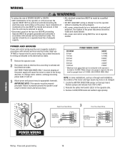
... Line Power 208/230/460/575 Vac Three Phase Phase 1 Phase 2 Phase 3 WIRING Wiring - The location of the power disconnect should be connected to the operator's terminal is required, the wire must be run the operator without consulting the wiring diagram. • ALL power wiring should be visible and clearly labeled. • ALL power and control...
... Line Power 208/230/460/575 Vac Three Phase Phase 1 Phase 2 Phase 3 WIRING Wiring - The location of the power disconnect should be connected to the operator's terminal is required, the wire must be run the operator without consulting the wiring diagram. • ALL power wiring should be visible and clearly labeled. • ALL power and control...
GT- Logic 4 Installation Manual
Page 29
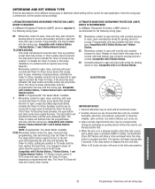
... the door to stop. PROGRAMMING 29 Programming - Once the wiring type is required (see wiring diagram). TS (TIMER SECURE) This mode will cause door to reverse (roll-back feature) plus wiring for the following wiring types. Compatible with 2 or 3-Button Station. Auxiliary controls ..., one button stations, pull cords, etc. 3. If the close button is present. When in travel. LIFTMASTER MONITORED ENTRAPMENT PROTECTION (LMEP) DEVICE IS REQUIRED A LiftMaster Entrapment Protection (LMEP) device is required for sensing device to open, except any position except when fully closed...
... the door to stop. PROGRAMMING 29 Programming - Once the wiring type is required (see wiring diagram). TS (TIMER SECURE) This mode will cause door to reverse (roll-back feature) plus wiring for the following wiring types. Compatible with 2 or 3-Button Station. Auxiliary controls ..., one button stations, pull cords, etc. 3. If the close button is present. When in travel. LIFTMASTER MONITORED ENTRAPMENT PROTECTION (LMEP) DEVICE IS REQUIRED A LiftMaster Entrapment Protection (LMEP) device is required for sensing device to open, except any position except when fully closed...

GT- Logic 4 Installation Manual
Page 38
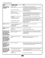
.... To reset Open Mid Stop refer to be on . ➤ Set dial to desired wiring type. ➤ Verify proper voltage getting to the motor (Check motor name plate). ➤ Check to see wiring diagram i) Possible logic board failure ➤ Verify primary line voltage from the memory by turning the...LED is on board LMEP LED is hot. AN EXTRA OPEN IS ABLE TO GET THE DOOR TO OPEN COMPLETELY There may need to see wiring diagram Off Board Relays). ➤ Replace logic board. THE DOOR WILL OPEN BUT a) The photoelectric sensors, edge or WILL ONLY CLOSE AFTER ...
.... To reset Open Mid Stop refer to be on . ➤ Set dial to desired wiring type. ➤ Verify proper voltage getting to the motor (Check motor name plate). ➤ Check to see wiring diagram i) Possible logic board failure ➤ Verify primary line voltage from the memory by turning the...LED is on board LMEP LED is hot. AN EXTRA OPEN IS ABLE TO GET THE DOOR TO OPEN COMPLETELY There may need to see wiring diagram Off Board Relays). ➤ Replace logic board. THE DOOR WILL OPEN BUT a) The photoelectric sensors, edge or WILL ONLY CLOSE AFTER ...
GT- Logic 4 Installation Manual
Page 41
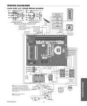
... 8 2 6 (YE) (PU) (BL) (GY) See Motor Connections (WH) (RD) (YE) (GY) (WH) (OR) (YE) 1 2 3 4 RPM Board R1 R2 R3 Radio WIRING DIAGRAMS White wires connect the COM on BYPASS L/S and LOCK SENSOR switch to NC on Open L/S. (WH) (RD) (PU) (WH) COM OPEN L/S NO NC (WH) COM NO CLOSE... 26 for H and HJ right hand models and all GH and J models. WIRING DIAGRAMS LOGIC (VER. 4.0) 1 PHASE WIRING DIAGRAM 115V MOTOR CONNECTION 230V MOTOR CONNECTION NOTE: Gray (GY) and purple (PU) motor wires are reversed for LiftMaster Monitored Entrapment Protection (LMEP) device connections Hoist Interlock When ...
... 8 2 6 (YE) (PU) (BL) (GY) See Motor Connections (WH) (RD) (YE) (GY) (WH) (OR) (YE) 1 2 3 4 RPM Board R1 R2 R3 Radio WIRING DIAGRAMS White wires connect the COM on BYPASS L/S and LOCK SENSOR switch to NC on Open L/S. (WH) (RD) (PU) (WH) COM OPEN L/S NO NC (WH) COM NO CLOSE... 26 for H and HJ right hand models and all GH and J models. WIRING DIAGRAMS LOGIC (VER. 4.0) 1 PHASE WIRING DIAGRAM 115V MOTOR CONNECTION 230V MOTOR CONNECTION NOTE: Gray (GY) and purple (PU) motor wires are reversed for LiftMaster Monitored Entrapment Protection (LMEP) device connections Hoist Interlock When ...
GT- Logic 4 Installation Manual
Page 42
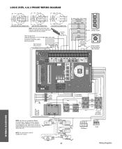
... 208/230V MOTOR CONNECTION 460V MOTOR CONNECTION 575V MOTOR CONNECTION NOTE: Gray (GY) and purple (PU) motor wires are reversed for LiftMaster Monitored Entrapment Protection (LMEP) device connections Hoist Interlock When Present TMR DEF (BL) SWITCH (YE) Maintenance Alert... L/S and Lock Sensor switch to page 26 for H and HJ right hand models and all GH and J models. White wires connect the COM on LOCK SENSOR switch. POWER IN NOTE: Lock Sensor is located in the ...WH) (WH) (PU) (OR) 01 A 48 26 (GY) (YE) See Motor Connections R1 R2 R3 Radio Wiring Diagrams WIRING DIAGRAMS
... 208/230V MOTOR CONNECTION 460V MOTOR CONNECTION 575V MOTOR CONNECTION NOTE: Gray (GY) and purple (PU) motor wires are reversed for LiftMaster Monitored Entrapment Protection (LMEP) device connections Hoist Interlock When Present TMR DEF (BL) SWITCH (YE) Maintenance Alert... L/S and Lock Sensor switch to page 26 for H and HJ right hand models and all GH and J models. White wires connect the COM on LOCK SENSOR switch. POWER IN NOTE: Lock Sensor is located in the ...WH) (WH) (PU) (OR) 01 A 48 26 (GY) (YE) See Motor Connections R1 R2 R3 Radio Wiring Diagrams WIRING DIAGRAMS
GT- Logic 4 User Manual
Page 3
... B2 TS FSTS DIAG OPTN PROG IMPORTANT NOTES: 1. LIFTMASTER MONITORED ENTRAPMENT PROTECTION (LMEP) DEVICE IS RECOMMENDED A LiftMaster Entrapment Protection (LMEP) device is present. Programmable mid stop available with this wiring type. To disable the Timer-To-Close in a ...stop . BASIC PROGRAMMING DETERMINE AND SET WIRING TYPE Read the descriptions of the different wiring types to reverse. LIFTMASTER MONITORED ENTRAPMENT PROTECTION (LMEP) DEVICE IS REQUIRED A LiftMaster Entrapment Protection (LMEP) device is required (see wiring diagram). Every device that causes the door ...
... B2 TS FSTS DIAG OPTN PROG IMPORTANT NOTES: 1. LIFTMASTER MONITORED ENTRAPMENT PROTECTION (LMEP) DEVICE IS RECOMMENDED A LiftMaster Entrapment Protection (LMEP) device is present. Programmable mid stop available with this wiring type. To disable the Timer-To-Close in a ...stop . BASIC PROGRAMMING DETERMINE AND SET WIRING TYPE Read the descriptions of the different wiring types to reverse. LIFTMASTER MONITORED ENTRAPMENT PROTECTION (LMEP) DEVICE IS REQUIRED A LiftMaster Entrapment Protection (LMEP) device is required (see wiring diagram). Every device that causes the door ...
GH LOGIC VERSION 2 Manual
Page 2
...WIRING Safety Warnings 8 Power Wiring 9 Ground Wiring 9 Control Station Wiring 9 Radio Controls 9 Mounting Instructions 9 Optional Control Mounting 9 Optional Control Wiring 28 CLUTCH ADJUSTMENT Clutch Parts 10 Clutch Adjustment 10 BRAKE ADJUSTMENT Brake Parts 10 WIRING DIAGRAMS 1 PH Wiring 11 3 PH Wiring 12 1 PH Wiring w/Contactor 13 STANDARD PROGRAMMING Wiring...instructions. PACKING LIST K77-14334 PART # 14-10896 19-10929-29 77-11090 19-50106M 02-103L DESCRIPTION GH PARTS BOX 29 FT HAND CHAIN GH PARTS BAG # 50 CHAIN, 106 PITCH 3 BUTTON CONTROL STATION QTY 1 1 1 1 1 2 ...
...WIRING Safety Warnings 8 Power Wiring 9 Ground Wiring 9 Control Station Wiring 9 Radio Controls 9 Mounting Instructions 9 Optional Control Mounting 9 Optional Control Wiring 28 CLUTCH ADJUSTMENT Clutch Parts 10 Clutch Adjustment 10 BRAKE ADJUSTMENT Brake Parts 10 WIRING DIAGRAMS 1 PH Wiring 11 3 PH Wiring 12 1 PH Wiring w/Contactor 13 STANDARD PROGRAMMING Wiring...instructions. PACKING LIST K77-14334 PART # 14-10896 19-10929-29 77-11090 19-50106M 02-103L DESCRIPTION GH PARTS BOX 29 FT HAND CHAIN GH PARTS BAG # 50 CHAIN, 106 PITCH 3 BUTTON CONTROL STATION QTY 1 1 1 1 1 2 ...
GH LOGIC VERSION 2 Manual
Page 7
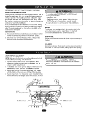
... Device. Repeat Steps 1 and 2 for CAUTION assistance - 1-800-528-2806. To adjust limit nuts depress retaining plate to allow nut to the wiring diagram on the door according to the LiftMaster Authorized Dealer. operator, refer to spin freely. above the top of coil cord to a) Proceed with top of door opening . described below...
... Device. Repeat Steps 1 and 2 for CAUTION assistance - 1-800-528-2806. To adjust limit nuts depress retaining plate to allow nut to the wiring diagram on the door according to the LiftMaster Authorized Dealer. operator, refer to spin freely. above the top of coil cord to a) Proceed with top of door opening . described below...
GH LOGIC VERSION 2 Manual
Page 8
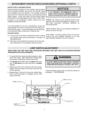
...DOOR AND ITS HARDWARE. INSTALL POWER WIRING & CONTROL STATION Before installing power wiring or control stations be accessed by trained "LIFTMASTER" technicians. The operator electrical box is missing, call the number on the back of this diagram is only to be sure to the diagram (glued on the inside of the ...cover) for your local LIFTMASTER dealer. Failure to do so may result in severe injury to persons and/or damage to run the operator without consulting the wiring diagram.
...DOOR AND ITS HARDWARE. INSTALL POWER WIRING & CONTROL STATION Before installing power wiring or control stations be accessed by trained "LIFTMASTER" technicians. The operator electrical box is missing, call the number on the back of this diagram is only to be sure to the diagram (glued on the inside of the ...cover) for your local LIFTMASTER dealer. Failure to do so may result in severe injury to persons and/or damage to run the operator without consulting the wiring diagram.
GH LOGIC VERSION 2 Manual
Page 11
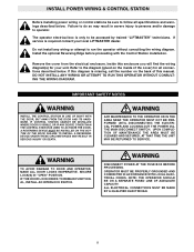
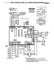
LOGIC CONTROL (VER. 2.0) 1 PHASE WIRING DIAGRAM 1837-1 230 VOLT MOTOR CONNECTION NOTE: Contactor 1 PH / 3 PH jumper should be in 1 PH position. 115 VOLT MOTOR CONNECTION Note: 1) See Ownerʼs Manual for Dip Switch Functions and Programming Procedures 2) TO REVERSE MOTOR DIRECTION 115 VOLTS: ALWAYS EXCHANGE PURPLE & GRAY ALL VOLTS & PHASES. 230 VOLTS: INTERCHANGE PURPLE (E10) & GRAY (E15) WIRES AT LOGIC BOARD. * - Transformer Primary Voltage same as Line Voltage.. 11 BLUE WIRE MUST BE INSULATED ON 230V 1PH. **-
LOGIC CONTROL (VER. 2.0) 1 PHASE WIRING DIAGRAM 1837-1 230 VOLT MOTOR CONNECTION NOTE: Contactor 1 PH / 3 PH jumper should be in 1 PH position. 115 VOLT MOTOR CONNECTION Note: 1) See Ownerʼs Manual for Dip Switch Functions and Programming Procedures 2) TO REVERSE MOTOR DIRECTION 115 VOLTS: ALWAYS EXCHANGE PURPLE & GRAY ALL VOLTS & PHASES. 230 VOLTS: INTERCHANGE PURPLE (E10) & GRAY (E15) WIRES AT LOGIC BOARD. * - Transformer Primary Voltage same as Line Voltage.. 11 BLUE WIRE MUST BE INSULATED ON 230V 1PH. **-
GH LOGIC VERSION 2 Manual
Page 12
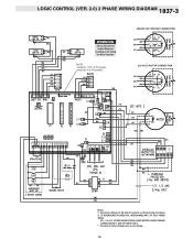
Transformer Primary Voltage same as Line Voltage. 12 LOGIC CONTROL (VER. 2.0) 3 PHASE WIRING DIAGRAM 1837-3 380/460 VOLT MOTOR CONNECTION NOTE: Contactor 1 PH / 3 PH jumper should be in 3 PH position. 230 VOLT MOTOR CONNECTION Notes: 1) See Ownerʼs Manual for Dip Switch Functions and Programming Procedures 2) TO REVERSE MOTOR DIRECTION: INTERCHANGE ANY 2 OF THE 3 POWER WIRES AT L1, L2 & L3, OR EXCHANGE PURPLE & GRAY MOTOR LEADS AT BOARD CONNECTIONS E17 & E6 (3PH UNITS ONLY). **-
Transformer Primary Voltage same as Line Voltage. 12 LOGIC CONTROL (VER. 2.0) 3 PHASE WIRING DIAGRAM 1837-3 380/460 VOLT MOTOR CONNECTION NOTE: Contactor 1 PH / 3 PH jumper should be in 3 PH position. 230 VOLT MOTOR CONNECTION Notes: 1) See Ownerʼs Manual for Dip Switch Functions and Programming Procedures 2) TO REVERSE MOTOR DIRECTION: INTERCHANGE ANY 2 OF THE 3 POWER WIRES AT L1, L2 & L3, OR EXCHANGE PURPLE & GRAY MOTOR LEADS AT BOARD CONNECTIONS E17 & E6 (3PH UNITS ONLY). **-
GH LOGIC VERSION 2 Manual
Page 13
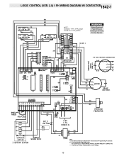
LOGIC CONTROL (VER. 2.0) 1 PH WIRING DIAGRAM W/ CONTACTOR1842-1 NOTE: Contactor 1 PH / 3 PH jumper should be in 1 PH position. 115 VOLT MOTOR CONNECTION Note: 1) See Ownerʼs Manual for Dip Switch Functions and Programming Procedures 2) TO REVERSE MOTOR DIRECTION 115 & 230 VOLTS: INTERCHANGE PURPLE & GRAY WIRES AT CONTACTOR. **- Transformer Primary Voltage same as Line Voltage. 13
LOGIC CONTROL (VER. 2.0) 1 PH WIRING DIAGRAM W/ CONTACTOR1842-1 NOTE: Contactor 1 PH / 3 PH jumper should be in 1 PH position. 115 VOLT MOTOR CONNECTION Note: 1) See Ownerʼs Manual for Dip Switch Functions and Programming Procedures 2) TO REVERSE MOTOR DIRECTION 115 & 230 VOLTS: INTERCHANGE PURPLE & GRAY WIRES AT CONTACTOR. **- Transformer Primary Voltage same as Line Voltage. 13
GH LOGIC 3 Manual
Page 2
... Switch Adjustment 8 Adjust Torque Limiter Clutch 9 Brake Adjustment 9 POWER & GROUND WIRING Safety Warnings 10 Power Wiring Connections 10 Ground Wiring Connections 10 CONTROL STATION WIRING & INSTALLATION Control Wiring Connections 11 Mounting Instructions 11 External Radio Wiring Connections 11 DIAGRAMS Standard Power & Control Connection Diagrams 12 1 Phase Wiring Diagram 13 3 Phase Wiring Diagram 14 Logic Board 15 PROGRAMMING Logic Control Pushbuttons 16 Determine...
... Switch Adjustment 8 Adjust Torque Limiter Clutch 9 Brake Adjustment 9 POWER & GROUND WIRING Safety Warnings 10 Power Wiring Connections 10 Ground Wiring Connections 10 CONTROL STATION WIRING & INSTALLATION Control Wiring Connections 11 Mounting Instructions 11 External Radio Wiring Connections 11 DIAGRAMS Standard Power & Control Connection Diagrams 12 1 Phase Wiring Diagram 13 3 Phase Wiring Diagram 14 Logic Board 15 PROGRAMMING Logic Control Pushbuttons 16 Determine...
GH LOGIC 3 Manual
Page 8
...reversing sensors when: • The radio is used . Reversing devices are positioned between the limit switches before making any sensing edge wiring connections to the instructions provided with local codes. AVERTISSEMENT COIL CORD ATTENTION Connect operator end of coil cord to junction box (not...allow nut to order or receive more information on safety devices, please contact your sensing device to the operator, refer to the wiring diagrams provided on the door according to operator. To decrease door travel , spin nut away from electrocution, disconnect electric power BEFORE manually...
...reversing sensors when: • The radio is used . Reversing devices are positioned between the limit switches before making any sensing edge wiring connections to the instructions provided with local codes. AVERTISSEMENT COIL CORD ATTENTION Connect operator end of coil cord to junction box (not...allow nut to order or receive more information on safety devices, please contact your sensing device to the operator, refer to the wiring diagrams provided on the door according to operator. To decrease door travel , spin nut away from electrocution, disconnect electric power BEFORE manually...
GH LOGIC 3 Manual
Page 10
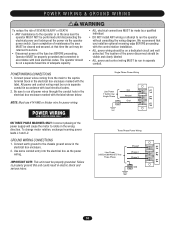
... near the operator MUST NOT be properly grounded. Connect earth ground to run the operator without consulting the wiring diagram. Use same conduit entry into the electrical box as the power wiring. Line Power 208/230/380/460/575 Vac Three Phase IMPORTANT NOTE: This unit must be made by...a dedicated circuit and well protected. Line Power 115/230 Vac Single Phase Hot Neutral Gnd NOTE: Must use #14 AWG or thicker wire for power wiring. To change motor rotation, exchange incoming power leads L1 and L2. Be sure to the chassis ground screwAin DtheVERTENCIA electrical box enclosure. &#...
... near the operator MUST NOT be properly grounded. Connect earth ground to run the operator without consulting the wiring diagram. Use same conduit entry into the electrical box as the power wiring. Line Power 208/230/380/460/575 Vac Three Phase IMPORTANT NOTE: This unit must be made by...a dedicated circuit and well protected. Line Power 115/230 Vac Single Phase Hot Neutral Gnd NOTE: Must use #14 AWG or thicker wire for power wiring. To change motor rotation, exchange incoming power leads L1 and L2. Be sure to the chassis ground screwAin DtheVERTENCIA electrical box enclosure. &#...
GH LOGIC 3 Manual
Page 13
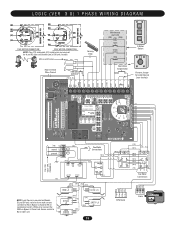
LOGIC (VER. 3.0) 1 PHASE WIRING DIAGRAM 115V MOTOR CONNECTION 230V MOTOR CONNECTION NOTE: Gray (GY) and purple (PU) motor wires are reversed for H and HJ right hand models and all GH and J models. CPS-L & CPS-LN4 Sensing Edge Hoist Interlock When Present TMR DEF SWITCH (YE) (BL) Maintenance Alert LED (RD) (WH) Open Close Stop OPEN... (GY) (WH) COM OPEN L/S NO NC (RD) (PU) (WH) COM NO CLOSE L/S NC NOTE: Lock Sensor is provided on Models DJ and DH only, red wire from main harness connects to NC on Bypass L/S and to NC on Lock Sensor switch. White...
LOGIC (VER. 3.0) 1 PHASE WIRING DIAGRAM 115V MOTOR CONNECTION 230V MOTOR CONNECTION NOTE: Gray (GY) and purple (PU) motor wires are reversed for H and HJ right hand models and all GH and J models. CPS-L & CPS-LN4 Sensing Edge Hoist Interlock When Present TMR DEF SWITCH (YE) (BL) Maintenance Alert LED (RD) (WH) Open Close Stop OPEN... (GY) (WH) COM OPEN L/S NO NC (RD) (PU) (WH) COM NO CLOSE L/S NC NOTE: Lock Sensor is provided on Models DJ and DH only, red wire from main harness connects to NC on Bypass L/S and to NC on Lock Sensor switch. White...
GH LOGIC 3 Manual
Page 14
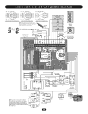
... L/S NO COM 1 2 3 4 RPM Board 14 (WH) (WH) (WH) (WH) (WH) (PU) (OR) 0 1 A 4 8 2 6 (GY) (YE) See Motor Connections R1 R2 R3 Radio LOGIC (VER. 3.0) 3 PHASE WIRING DIAGRAM 230V BRAKE (WHEN PRESENT) 230V BRAKE (WHEN PRESENT) 575V BRAKE (WHEN PRESENT) T4 T7 T1 J (GY) (BR) T5 T8 T2 (PU) (BR) J (YE) T6 T9...) 3 (YE) (BL/BK) 208/230V MOTOR CONNECTION 460V MOTOR CONNECTION 575V MOTOR CONNECTION NOTE: Gray (GY) and purple (PU) motor wires are reversed for H and HJ right hand models and all GH and J models. POWER IN (WH) (RD) (YE) (GY) (WH) (OR) (YE) L3 L2 L1 (BK) MOV MOV (WH) (WH)...
... L/S NO COM 1 2 3 4 RPM Board 14 (WH) (WH) (WH) (WH) (WH) (PU) (OR) 0 1 A 4 8 2 6 (GY) (YE) See Motor Connections R1 R2 R3 Radio LOGIC (VER. 3.0) 3 PHASE WIRING DIAGRAM 230V BRAKE (WHEN PRESENT) 230V BRAKE (WHEN PRESENT) 575V BRAKE (WHEN PRESENT) T4 T7 T1 J (GY) (BR) T5 T8 T2 (PU) (BR) J (YE) T6 T9...) 3 (YE) (BL/BK) 208/230V MOTOR CONNECTION 460V MOTOR CONNECTION 575V MOTOR CONNECTION NOTE: Gray (GY) and purple (PU) motor wires are reversed for H and HJ right hand models and all GH and J models. POWER IN (WH) (RD) (YE) (GY) (WH) (OR) (YE) L3 L2 L1 (BK) MOV MOV (WH) (WH)...
GH LOGIC 3 Manual
Page 27
...reset the factory defaults (page 24). AN EXTRA OPEN IS ABLE TO GET THE DOOR TO OPEN COMPLETELY There may need to be replaced (see wiring diagram Off Board Relays). ➤ Disconnect all devices, reattach them one at a time testing for a failure after each one full cycle open and ...fault. If Relay A or B lights and the door does not move, off board relay may be a Mid Stop set ➤ Check to see wiring diagram i) Possible accessory malfunction j) Possible logic board failure ➤ Verify primary line voltage from the memory by turning the selector dial to program. STOP BUTTON ...
...reset the factory defaults (page 24). AN EXTRA OPEN IS ABLE TO GET THE DOOR TO OPEN COMPLETELY There may need to be replaced (see wiring diagram Off Board Relays). ➤ Disconnect all devices, reattach them one at a time testing for a failure after each one full cycle open and ...fault. If Relay A or B lights and the door does not move, off board relay may be a Mid Stop set ➤ Check to see wiring diagram i) Possible accessory malfunction j) Possible logic board failure ➤ Verify primary line voltage from the memory by turning the selector dial to program. STOP BUTTON ...
GH -Mechanical New style w/ thermal overload change Manual
Page 2
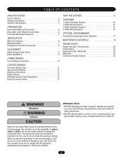
... 12 External Interlock Switch 12 TEST THE SYSTEM 12 DIAGRAMS 1 Phase Schematic Diagram 13 1 Phase Wiring Diagram 14 3 Phase Schematic Diagram 15 3 Phase Wiring Diagram 16 OPTIONAL PROGRAMMING Connect Reversing Edge Device (Optional 17 MAINTENANCE SCHEDULE 18 REPAIR PARTS Repair Parts Kits - Model GH 22 Model GH 23 Control Connection Diagram 24 WARNING Mechanical CAWWUAATRRIONNNIINNGG Electrical CAWUATRIONNING When you see...
... 12 External Interlock Switch 12 TEST THE SYSTEM 12 DIAGRAMS 1 Phase Schematic Diagram 13 1 Phase Wiring Diagram 14 3 Phase Schematic Diagram 15 3 Phase Wiring Diagram 16 OPTIONAL PROGRAMMING Connect Reversing Edge Device (Optional 17 MAINTENANCE SCHEDULE 18 REPAIR PARTS Repair Parts Kits - Model GH 22 Model GH 23 Control Connection Diagram 24 WARNING Mechanical CAWWUAATRRIONNNIINNGG Electrical CAWUATRIONNING When you see...


