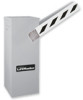
BG790 Manual
Page 2
...intended to install, operate or maintain the operator, you do not comply with the warnings that accompany them carefully. 2 Model BG770 16 Repair Parts - TABLE OF CONTENTS SPECIFICATIONS Operator Specifications 3 Operator Dimensions 3 OPERATOR WARNINGS Safety Installation Information 4 PREPARATION Carton... Model BG790 19 MAINTENANCE Limited Bearing Lubrication 20 Grease Turnbuckle 20 WIRING DIAGRAMS Single Phase Wiring Diagram 21 Three Phase Wiring Diagram 22 Control Connection Diagram 23 WARRANTY POLICY AND SERVICE 24 IMPORTANT NOTES • BEFORE attempting to be ...
...intended to install, operate or maintain the operator, you do not comply with the warnings that accompany them carefully. 2 Model BG770 16 Repair Parts - TABLE OF CONTENTS SPECIFICATIONS Operator Specifications 3 Operator Dimensions 3 OPERATOR WARNINGS Safety Installation Information 4 PREPARATION Carton... Model BG790 19 MAINTENANCE Limited Bearing Lubrication 20 Grease Turnbuckle 20 WIRING DIAGRAMS Single Phase Wiring Diagram 21 Three Phase Wiring Diagram 22 Control Connection Diagram 23 WARRANTY POLICY AND SERVICE 24 IMPORTANT NOTES • BEFORE attempting to be ...
BG790 Manual
Page 7
...SEVERE INJURY or DEATH: • ANY maintenance to the operator or in the switch box for connection of the gate. The BG770 and BG790 barrier gates will mount the control station outdoors, replace the standard station supplied with the operator with the gate to ...in the housing. 7 MODEL BG790: Hang electrical enclosure on the two screws provided on the operator wiring diagram. Operator MUST be mounted in step 7. 1. Connect power supply wires to the wiring diagram for connection of commonly used control stations, radio controls, and access control equipment. Refer to the...
...SEVERE INJURY or DEATH: • ANY maintenance to the operator or in the switch box for connection of the gate. The BG770 and BG790 barrier gates will mount the control station outdoors, replace the standard station supplied with the operator with the gate to ...in the housing. 7 MODEL BG790: Hang electrical enclosure on the two screws provided on the operator wiring diagram. Operator MUST be mounted in step 7. 1. Connect power supply wires to the wiring diagram for connection of commonly used control stations, radio controls, and access control equipment. Refer to the...
BG790 Manual
Page 12
... set of the four board mount standoffs located on the wiring diagrams supplied with the gate and with the radio connections. MOUNTING LOCATION Mount or install the access control device within sight of the gate and according to models BG770 and BG790. Some devices require their own power supply. ...If yours does not, or if you are finished with the detector itself. FACTORY SUPPLIED PLUG-IN DETECTORS LiftMaster P/N 71-416-7NH = 24V PLEASE NOTE: Previous models ...
... set of the four board mount standoffs located on the wiring diagrams supplied with the gate and with the radio connections. MOUNTING LOCATION Mount or install the access control device within sight of the gate and according to models BG770 and BG790. Some devices require their own power supply. ...If yours does not, or if you are finished with the detector itself. FACTORY SUPPLIED PLUG-IN DETECTORS LiftMaster P/N 71-416-7NH = 24V PLEASE NOTE: Previous models ...
BG790 Manual
Page 15
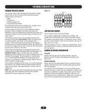
...problem may have a separate overload in the controller (Model BG770 uses a manual reset overload). Disconnect Power! Using a volt-ohmmeter, take continuity readings across the contacts of the contactor's contact points. Remove wires from the gate. you will require technical assistance, contact your...; There are S.P.D.T. (single pole, double throw). These limit switches tell the operator to the operator. 15 WIRING DIAGRAM Always reference the wiring diagram that was supplied with an insulated handle, press down on the open or full close direction. If you cannot...
...problem may have a separate overload in the controller (Model BG770 uses a manual reset overload). Disconnect Power! Using a volt-ohmmeter, take continuity readings across the contacts of the contactor's contact points. Remove wires from the gate. you will require technical assistance, contact your...; There are S.P.D.T. (single pole, double throw). These limit switches tell the operator to the operator. 15 WIRING DIAGRAM Always reference the wiring diagram that was supplied with an insulated handle, press down on the open or full close direction. If you cannot...
BG790 Manual
Page 21
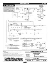
... TO CAUSE GATE ARM TO CLOSE IMMEDIATELY UNLESS HOLD OPEN LOOP IS ACTIVATED. (OR) OP 56 1 CL 2 (1 of rating. WIRING DIAGRAM To protect against fire and electrocution: • DISCONNECT power BEFORE installing or servicing operator. • Replace ONLY with fuse of same ...AS OPERATOR LINE VOLTAGE. 3) WE RECOMMEND USING A DEDICATED CIRCUIT BREAKER FOR EACH OPERATOR. 4) BROWN WIRES INSIDE MOTOR NOT USED, SHOULD BE WIRE NUTTED. APPLICATIONS: CONTROL WIRING TYPE L2 MODEL TYPES: FIELD WIRING BG770, BG790 HORSEPOWER: VOLTAGE/PHASE: 1/2 115/230V, 60Hz, 1 PHASE ONLY DRAWING NUMBER: DATE:...
... TO CAUSE GATE ARM TO CLOSE IMMEDIATELY UNLESS HOLD OPEN LOOP IS ACTIVATED. (OR) OP 56 1 CL 2 (1 of rating. WIRING DIAGRAM To protect against fire and electrocution: • DISCONNECT power BEFORE installing or servicing operator. • Replace ONLY with fuse of same ...AS OPERATOR LINE VOLTAGE. 3) WE RECOMMEND USING A DEDICATED CIRCUIT BREAKER FOR EACH OPERATOR. 4) BROWN WIRES INSIDE MOTOR NOT USED, SHOULD BE WIRE NUTTED. APPLICATIONS: CONTROL WIRING TYPE L2 MODEL TYPES: FIELD WIRING BG770, BG790 HORSEPOWER: VOLTAGE/PHASE: 1/2 115/230V, 60Hz, 1 PHASE ONLY DRAWING NUMBER: DATE:...
BG790 Manual
Page 22
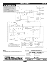
...CONNECTION MOTOR CONNECTION SAME (GN) AS INCOMING POWER (BL) (R) (W) (BL) 1 74 J 28 5 208/230V MOTOR 3 9 6 J CONNECTION 115V GEARBOX HEATER (BK) H2 WIRE COLOR: 208V-(R), 230V-(OR), 480-(VT), 575V-(GY) (GN) (BL) 1 (R) 2 (W) (BL) 3 J 575V MOTOR CONNECTION J (OPTIONAL EQUIPMENT) (YEL) 4 (YEL)... OPERATOR. 1 APPLICATIONS: CONTROL WIRING TYPE FIELD WIRING & ADJUSTMENTS MODEL TYPES: HORSEPOWER: VOLTAGE/PHASE: BG770 (PG) BG790 (HBG) 1/2 208/230/480/575V DRAWING NUMBER: 01-G1015 DATE: 08/28/00 REVISION: E-3/20/08 ECN: 08-7165 22 WIRING DIAGRAM (1 of 2) To protect against...
...CONNECTION MOTOR CONNECTION SAME (GN) AS INCOMING POWER (BL) (R) (W) (BL) 1 74 J 28 5 208/230V MOTOR 3 9 6 J CONNECTION 115V GEARBOX HEATER (BK) H2 WIRE COLOR: 208V-(R), 230V-(OR), 480-(VT), 575V-(GY) (GN) (BL) 1 (R) 2 (W) (BL) 3 J 575V MOTOR CONNECTION J (OPTIONAL EQUIPMENT) (YEL) 4 (YEL)... OPERATOR. 1 APPLICATIONS: CONTROL WIRING TYPE FIELD WIRING & ADJUSTMENTS MODEL TYPES: HORSEPOWER: VOLTAGE/PHASE: BG770 (PG) BG790 (HBG) 1/2 208/230/480/575V DRAWING NUMBER: 01-G1015 DATE: 08/28/00 REVISION: E-3/20/08 ECN: 08-7165 22 WIRING DIAGRAM (1 of 2) To protect against...
BG790 Manual
Page 23
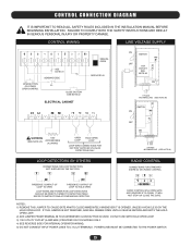
.... POWER LINES MUST BE CONNECTED TO THE POWER SWITCH. 23 CONTROL CONNECTION DIAGRAM IT IS IMPORTANT TO READ ALL SAFETY RULES INCLUDED IN THE INSTALLATION MANUAL BEFORE BEGINNING INSTALLATION. CONTROL WIRING LINE VOLTAGE SUPPLY OPEN BUTTON OR OTHER OPEN CONTROL SEE NOTE #1 SENSING... CLOSE BUTTON SEE NOTE #2 ELECTRICAL CABINET MANUAL OPEN SEE NOTE #2 WARNING 115V (SEE NOTE #5) ACCESSORIES (0.2A MAX) OPEN LOOP HOLD OPEN LOOP LOOP WIRE CONNECTIONS FOR FACTORY SUPPLIED (PLUG-IN) DETECTORS ONLY ON OFF SWITCH (BK) 115V (W) OUTLET SEE NOTE #3 (GN) 1 PHASE INCOMING LINE (SEE ...
.... POWER LINES MUST BE CONNECTED TO THE POWER SWITCH. 23 CONTROL CONNECTION DIAGRAM IT IS IMPORTANT TO READ ALL SAFETY RULES INCLUDED IN THE INSTALLATION MANUAL BEFORE BEGINNING INSTALLATION. CONTROL WIRING LINE VOLTAGE SUPPLY OPEN BUTTON OR OTHER OPEN CONTROL SEE NOTE #1 SENSING... CLOSE BUTTON SEE NOTE #2 ELECTRICAL CABINET MANUAL OPEN SEE NOTE #2 WARNING 115V (SEE NOTE #5) ACCESSORIES (0.2A MAX) OPEN LOOP HOLD OPEN LOOP LOOP WIRE CONNECTIONS FOR FACTORY SUPPLIED (PLUG-IN) DETECTORS ONLY ON OFF SWITCH (BK) 115V (W) OUTLET SEE NOTE #3 (GN) 1 PHASE INCOMING LINE (SEE ...


