BG790 Manual
Page 1
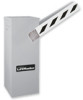
OWNER'S MANUAL MODELS BG770 & BG790 VEHICULAR BARRIER GATE OPERATOR MODELS BG770 AND BG790 ARE FOR VEHICULAR PASSAGE GATES ONLY AND ARE NOT INTENDED FOR PEDESTRIAN PASSAGE GATE USE
OWNER'S MANUAL MODELS BG770 & BG790 VEHICULAR BARRIER GATE OPERATOR MODELS BG770 AND BG790 ARE FOR VEHICULAR PASSAGE GATES ONLY AND ARE NOT INTENDED FOR PEDESTRIAN PASSAGE GATE USE
BG790 Manual
Page 2
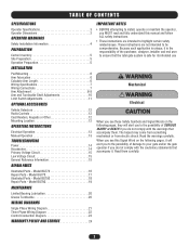
...on the following pages, it will alert you do not comply with the cautionary statements that accompany them carefully. 2 Model BG770 16 Repair Parts - The hazard may come from something mechanical or from electric shock. Because each application is unique...ALL safety instructions. • These instructions are intended to your gate and/or the gate operator if you to be comprehensive. Model BG770 17 Illustrated Parts - TABLE OF CONTENTS SPECIFICATIONS Operator Specifications 3 Operator Dimensions 3 OPERATOR WARNINGS Safety Installation Information 4 PREPARATION Carton ...
...on the following pages, it will alert you do not comply with the cautionary statements that accompany them carefully. 2 Model BG770 16 Repair Parts - The hazard may come from something mechanical or from electric shock. Because each application is unique...ALL safety instructions. • These instructions are intended to your gate and/or the gate operator if you to be comprehensive. Model BG770 17 Illustrated Parts - TABLE OF CONTENTS SPECIFICATIONS Operator Specifications 3 Operator Dimensions 3 OPERATOR WARNINGS Safety Installation Information 4 PREPARATION Carton ...
BG790 Manual
Page 3
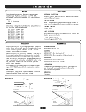
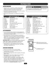
...all motor control equipment. Enclosure removable from operator. Activation of access device open button, or loop detector to 24' ARM SPEED MODEL BG770: Opens in 4 seconds MODEL BG790: Opens in 11 seconds LUBRICATION Permanently lubricated bearings in which case gate will remain open (N.O.) output contact (most access control... CLOSE button wiring has been made, in motor. MECHANICAL SPEED REDUCTION Wormgear-in-oil-bath, 60:1 ARM TYPE MODEL BG770: One piece type to 15' MODEL BG790: Counterweighted wishbone type to open will extend the time that the gate remains open. MOUNTING Pad mount...
...all motor control equipment. Enclosure removable from operator. Activation of access device open button, or loop detector to 24' ARM SPEED MODEL BG770: Opens in 4 seconds MODEL BG790: Opens in 11 seconds LUBRICATION Permanently lubricated bearings in which case gate will remain open (N.O.) output contact (most access control... CLOSE button wiring has been made, in motor. MECHANICAL SPEED REDUCTION Wormgear-in-oil-bath, 60:1 ARM TYPE MODEL BG770: One piece type to 15' MODEL BG790: Counterweighted wishbone type to open will extend the time that the gate remains open. MOUNTING Pad mount...
BG790 Manual
Page 5
... be in the OFF position. Open the cover of run. Refer to gate nameplate located inside service cover) accurately matches the operator that may result. MODEL BG770 PACKING LIST PART NUMBER DESCRIPTION QTY 02-102 Open/Close Push Button 1 07-8007 Gate Arm Hub 1 10-8007M Gate Bracket 1 80-G0187 Key, ...to the arm mounting flange) and remove. 3. Run electrical power to the site according to the dimensional drawings on model BG790). Damage to supply the gate. MODEL BG790 PACKING LIST PART NUMBER DESCRIPTION QTY 02-102 Open/Close Push Button 1 07-8007 Arm Hub 2 10-8055 ...
... be in the OFF position. Open the cover of run. Refer to gate nameplate located inside service cover) accurately matches the operator that may result. MODEL BG770 PACKING LIST PART NUMBER DESCRIPTION QTY 02-102 Open/Close Push Button 1 07-8007 Gate Arm Hub 1 10-8007M Gate Bracket 1 80-G0187 Key, ...to the arm mounting flange) and remove. 3. Run electrical power to the site according to the dimensional drawings on model BG790). Damage to supply the gate. MODEL BG790 PACKING LIST PART NUMBER DESCRIPTION QTY 02-102 Open/Close Push Button 1 07-8007 Arm Hub 2 10-8055 ...
BG790 Manual
Page 6
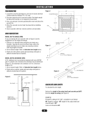
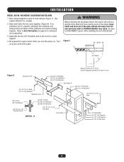
... 3" Length as required by local codes. 3. Refer to desired length. Secure operator with four concrete anchors (not provided). 13" 22" ARM FABRICATION MODEL BG770 (SINGLE ARM) If you to ceiling (see Figure 5). Refer to locate electrical Conduit Entry Area 14" conduit inside the hatched 14" x 13" area... allows you are making the arm yourself, refer to ceiling is 8'3" (99"), calculation is desired, the extension may be 59". 6 Figure 3 MODEL BG790 (WISHBONE ARM) 5-12" A 24' wishbone arm is 8' for pad and conduit. Tapering the wood as standard with long lengths of 24...
... 3" Length as required by local codes. 3. Refer to desired length. Secure operator with four concrete anchors (not provided). 13" 22" ARM FABRICATION MODEL BG770 (SINGLE ARM) If you to ceiling (see Figure 5). Refer to locate electrical Conduit Entry Area 14" conduit inside the hatched 14" x 13" area... allows you are making the arm yourself, refer to ceiling is 8'3" (99"), calculation is desired, the extension may be 59". 6 Figure 3 MODEL BG790 (WISHBONE ARM) 5-12" A 24' wishbone arm is 8' for pad and conduit. Tapering the wood as standard with long lengths of 24...
BG790 Manual
Page 7
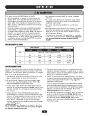
... BG790 barrier gate. The BG770 and BG790 barrier gates will mount the control station outdoors, replace the standard station supplied with the operator with the gate to follow ALL specifications and warnings described below . MODEL BG790: Hang electrical enclosure on the two screws provided ...The enclosure (shipped loose) may be sure to control the gate manually. Connect power supply wires to help in the housing. 7 MODEL BG770: Hang electrical enclosure on the two screws provided on the cross angle under shelf in the connections described below . INSTALLATION WARNING To reduce...
... BG790 barrier gate. The BG770 and BG790 barrier gates will mount the control station outdoors, replace the standard station supplied with the operator with the gate to follow ALL specifications and warnings described below . MODEL BG790: Hang electrical enclosure on the two screws provided ...The enclosure (shipped loose) may be sure to control the gate manually. Connect power supply wires to help in the housing. 7 MODEL BG770: Hang electrical enclosure on the two screws provided on the cross angle under shelf in the connections described below . INSTALLATION WARNING To reduce...
BG790 Manual
Page 8
... Washer DETAIL B (2) Flat Washers Hex Nut Hex Nut Hex Nut Flat Washer Threaded Spacer Flat Washer Flat Washer Hex Bolt 8 MODEL BG770: STANDARD ARM Attach arm to the arm hub flange (Figure 6). MODEL BG770: OPTIONAL ARM Attach arm to the arm hub flange (Figure 5). Be sure to DISCONNECT power while installing the arm attachment...
... Washer DETAIL B (2) Flat Washers Hex Nut Hex Nut Hex Nut Flat Washer Threaded Spacer Flat Washer Flat Washer Hex Bolt 8 MODEL BG770: STANDARD ARM Attach arm to the arm hub flange (Figure 6). MODEL BG770: OPTIONAL ARM Attach arm to the arm hub flange (Figure 5). Be sure to DISCONNECT power while installing the arm attachment...
BG790 Manual
Page 9
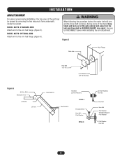
... 3/8" threaded rods to the arms for travel of Travel Ensure adequate clearance for center support. 4. Figure 7 18-5/8" 30" Radius Wishbone Arm Arc of arm. INSTALLATION MODEL BG790: WISHBONE COUNTERWEIGHTED ARM 1. Be sure to start when you turn and the drive shaft will move during some of arms clamps (Figure 7). Bend and...
... 3/8" threaded rods to the arms for travel of Travel Ensure adequate clearance for center support. 4. Figure 7 18-5/8" 30" Radius Wishbone Arm Arc of arm. INSTALLATION MODEL BG790: WISHBONE COUNTERWEIGHTED ARM 1. Be sure to start when you turn and the drive shaft will move during some of arms clamps (Figure 7). Bend and...
BG790 Manual
Page 10
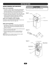
...factory. 2. Rotate the shaft either clockwise or counterclockwise as necessary until the gate arm is the lowest point of pivot arm (Figure 10). MODEL BG770 TURNBUCKLE SHAFT ALIGNMENT If necessary, align turnbuckle shaft with the turnbuckle shaft (Figure 9). Figure 9 Pivot Arm Pulley Crank Arm Jam Nut Turnbuckle... the gate arm is not level, loosen the jam nuts at the factory. 2. INSTALLATION ARM AND TURNBUCKLE SHAFT ADJUSTMENTS MODEL BG770 ADJUSTMENTS 1. Retighten jam nuts. This is raising, the upper and lower cranks should be preset in a vertical position (Figure 11...
...factory. 2. Rotate the shaft either clockwise or counterclockwise as necessary until the gate arm is the lowest point of pivot arm (Figure 10). MODEL BG770 TURNBUCKLE SHAFT ALIGNMENT If necessary, align turnbuckle shaft with the turnbuckle shaft (Figure 9). Figure 9 Pivot Arm Pulley Crank Arm Jam Nut Turnbuckle... the gate arm is not level, loosen the jam nuts at the factory. 2. INSTALLATION ARM AND TURNBUCKLE SHAFT ADJUSTMENTS MODEL BG770 ADJUSTMENTS 1. Retighten jam nuts. This is raising, the upper and lower cranks should be preset in a vertical position (Figure 11...
BG790 Manual
Page 12
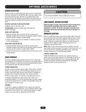
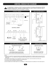
... power supply. Connect the detector(s) according to the instructions on the inside of the cabinet. FACTORY SUPPLIED PLUG-IN DETECTORS LiftMaster P/N 71-416-7NH = 24V PLEASE NOTE: Previous models used 115V detectors (P/N 71-416-3NH). Plug the harness into the connector marked "HOLD OPEN." 2. A standard residential ... four board mount standoffs located on the inside gate enclosure. RADIO CONTROLS All types of standard radio controls may be connected to models BG770 and BG790. POWER CONNECTION All radio receivers require a power supply. If yours does not, or if you are unsure of or...
... power supply. Connect the detector(s) according to the instructions on the inside of the cabinet. FACTORY SUPPLIED PLUG-IN DETECTORS LiftMaster P/N 71-416-7NH = 24V PLEASE NOTE: Previous models used 115V detectors (P/N 71-416-3NH). Plug the harness into the connector marked "HOLD OPEN." 2. A standard residential ... four board mount standoffs located on the inside gate enclosure. RADIO CONTROLS All types of standard radio controls may be connected to models BG770 and BG790. POWER CONNECTION All radio receivers require a power supply. If yours does not, or if you are unsure of or...
BG790 Manual
Page 15
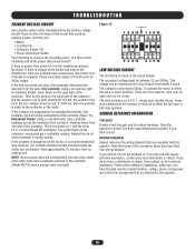
... volt-ohmmeter, take continuity readings across the contacts of the contactor. Repeat this circuit that some of the accessory items may have the gate operator model number, voltage, phase, horsepower and a list of all of the contactor. Wait approximately 15 minutes, then try running unit. The secondary voltage ...screwdriver with the operator. Is it did not, then the problem is the circuit breaker. Did the operator run in either in the controller (Model BG770 uses a manual reset overload). Check secondary output of the power disconnect switch? Remove wires from the gate.
... volt-ohmmeter, take continuity readings across the contacts of the contactor. Repeat this circuit that some of the accessory items may have the gate operator model number, voltage, phase, horsepower and a list of all of the contactor. Wait approximately 15 minutes, then try running unit. The secondary voltage ...screwdriver with the operator. Is it did not, then the problem is the circuit breaker. Did the operator run in either in the controller (Model BG770 uses a manual reset overload). Check secondary output of the power disconnect switch? Remove wires from the gate.
BG790 Manual
Page 17
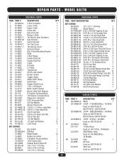
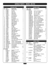
...-3050B-4E 1/2HP - 208/230/460Vac - 30-60Hz 1 Used on: BG770-50-23, 1 BG770-50-43, BG770-50-83 6 20-3050M-5 1/2HP - 575Vac - 30-60Hz 12 Used on: BG770-50-53 4 47 24-XXX-X Relay 1 24-115-1 115Vac Relay 1 Used on: All 115Vac, 10 Models 1 24-230-5 208/230Vac Relay 14 Used on: All 208.../230Vac, 1 10 Models 1 48 25-XXXX Fuse 1 1 25-2006 6A Fuse 8 1 2 25-2010 Used on: BG770-50-21 10A Fuse 1 Used on: BG770-50-11 17 MODEL BG770 INDIVIDUAL PARTS ITEM PART # 1 03-8024-K 2 07-8003 3 07-8004 4 07-8005 5 07-8007 6 10-3522 7 10-8001...
...-3050B-4E 1/2HP - 208/230/460Vac - 30-60Hz 1 Used on: BG770-50-23, 1 BG770-50-43, BG770-50-83 6 20-3050M-5 1/2HP - 575Vac - 30-60Hz 12 Used on: BG770-50-53 4 47 24-XXX-X Relay 1 24-115-1 115Vac Relay 1 Used on: All 115Vac, 10 Models 1 24-230-5 208/230Vac Relay 14 Used on: All 208.../230Vac, 1 10 Models 1 48 25-XXXX Fuse 1 1 25-2006 6A Fuse 8 1 2 25-2010 Used on: BG770-50-21 10A Fuse 1 Used on: BG770-50-11 17 MODEL BG770 INDIVIDUAL PARTS ITEM PART # 1 03-8024-K 2 07-8003 3 07-8004 4 07-8005 5 07-8007 6 10-3522 7 10-8001...
BG790 Manual
Page 18
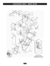
MODEL BG790 12 34 33 2 7 14 2 33 40 15 3 42 40 16 8 37 32 9 6 24 1 22 31 26 32 27 48 41 4 14 13 43 44 5 14 30 36 10 17 18 20 19 21 34 12 28 29 44 25 45 39 23 38 45 44 35 46 14 47 11 49 Operator Assembly (Wishbone Arm not shown) 18 ILLUSTRATED PARTS -
MODEL BG790 12 34 33 2 7 14 2 33 40 15 3 42 40 16 8 37 32 9 6 24 1 22 31 26 32 27 48 41 4 14 13 43 44 5 14 30 36 10 17 18 20 19 21 34 12 28 29 44 25 45 39 23 38 45 44 35 46 14 47 11 49 Operator Assembly (Wishbone Arm not shown) 18 ILLUSTRATED PARTS -
BG790 Manual
Page 19
REPAIR PARTS - MODEL BG790 INDIVIDUAL PARTS INDIVIDUAL PARTS ITEM PART # 1 03-8024-K 2 07-8007 3 07-8058 4 07-8063 5 07-8064 6 10-8014 7 10-8016-T 8 10-8017-T 9 10-8021 ...-60Hz Used on: BG790-50-53 48 24-XXX-X Relay 1 24-115-1 115Vac Relay Used on: All 115Vac, 10 Models 24-230-5 208/230Vac Relay Used on: All 208/230Vac, 10 Models 49 25-XXXX Fuse 1 25-2006 6A Fuse Used on: BG790-50-21 25-2010 10A Fuse Used on: BG790...
REPAIR PARTS - MODEL BG790 INDIVIDUAL PARTS INDIVIDUAL PARTS ITEM PART # 1 03-8024-K 2 07-8007 3 07-8058 4 07-8063 5 07-8064 6 10-8014 7 10-8016-T 8 10-8017-T 9 10-8021 ...-60Hz Used on: BG790-50-53 48 24-XXX-X Relay 1 24-115-1 115Vac Relay Used on: All 115Vac, 10 Models 24-230-5 208/230Vac Relay Used on: All 208/230Vac, 10 Models 49 25-XXXX Fuse 1 25-2006 6A Fuse Used on: BG790-50-21 25-2010 10A Fuse Used on: BG790...
BG790 Manual
Page 21
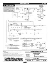
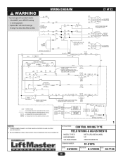
FOR BG770, INTERCHANGE GREEN AND RED WIRES (GN) BR (BK) (W) BR (R) 115V MOTOR CONNECTION YW 4 2 8 BK 5 OR BL 1 3 O/L SEE NOTE 4 (GN) W BR 4 (BK) R 8 (W) BK Y BL BR 523 (R) .... 3) WE RECOMMEND USING A DEDICATED CIRCUIT BREAKER FOR EACH OPERATOR. 4) BROWN WIRES INSIDE MOTOR NOT USED, SHOULD BE WIRE NUTTED. APPLICATIONS: CONTROL WIRING TYPE L2 MODEL TYPES: FIELD WIRING BG770, BG790 HORSEPOWER: VOLTAGE/PHASE: 1/2 115/230V, 60Hz, 1 PHASE ONLY DRAWING NUMBER: DATE: 08/28/00 01-G1014 REVISION: F-3/20/08 ECN: 08-7165...
FOR BG770, INTERCHANGE GREEN AND RED WIRES (GN) BR (BK) (W) BR (R) 115V MOTOR CONNECTION YW 4 2 8 BK 5 OR BL 1 3 O/L SEE NOTE 4 (GN) W BR 4 (BK) R 8 (W) BK Y BL BR 523 (R) .... 3) WE RECOMMEND USING A DEDICATED CIRCUIT BREAKER FOR EACH OPERATOR. 4) BROWN WIRES INSIDE MOTOR NOT USED, SHOULD BE WIRE NUTTED. APPLICATIONS: CONTROL WIRING TYPE L2 MODEL TYPES: FIELD WIRING BG770, BG790 HORSEPOWER: VOLTAGE/PHASE: 1/2 115/230V, 60Hz, 1 PHASE ONLY DRAWING NUMBER: DATE: 08/28/00 01-G1014 REVISION: F-3/20/08 ECN: 08-7165...
BG790 Manual
Page 22
... VOLTAGE SAME AS OPERATOR LINE VOLTAGE 24V SECONDARY 2) WE RECOMMEND USING A DEDICATED CIRCUIT BREAKER FOR EACH OPERATOR. 1 APPLICATIONS: CONTROL WIRING TYPE FIELD WIRING & ADJUSTMENTS MODEL TYPES: HORSEPOWER: VOLTAGE/PHASE: BG770 (PG) BG790 (HBG) 1/2 208/230/480/575V DRAWING NUMBER: 01-G1015 DATE: 08/28/00 REVISION: E-3/20/08 ECN: 08-7165 22
... VOLTAGE SAME AS OPERATOR LINE VOLTAGE 24V SECONDARY 2) WE RECOMMEND USING A DEDICATED CIRCUIT BREAKER FOR EACH OPERATOR. 1 APPLICATIONS: CONTROL WIRING TYPE FIELD WIRING & ADJUSTMENTS MODEL TYPES: HORSEPOWER: VOLTAGE/PHASE: BG770 (PG) BG790 (HBG) 1/2 208/230/480/575V DRAWING NUMBER: 01-G1015 DATE: 08/28/00 REVISION: E-3/20/08 ECN: 08-7165 22
BG790 Manual
Page 23
... IS OPENED, UNLESS A VEHICLE IS ON THE HOLD OPEN LOOP. DO NOT USE WITH HOLD OPEN LOOP. 3) 115V UTILITY OUTLET (4 AMP MAX.) PROVIDED ON 115V MODELS ONLY. 4) SEE REVERSE SIDE FOR INTERNAL OPERATOR WIRING. 5) DO NOT CONNECT INPUT POWER LINES TO L1 & L2 TERMINALS. CONTROL CONNECTION DIAGRAM IT IS IMPORTANT TO...
... IS OPENED, UNLESS A VEHICLE IS ON THE HOLD OPEN LOOP. DO NOT USE WITH HOLD OPEN LOOP. 3) 115V UTILITY OUTLET (4 AMP MAX.) PROVIDED ON 115V MODELS ONLY. 4) SEE REVERSE SIDE FOR INTERNAL OPERATOR WIRING. 5) DO NOT CONNECT INPUT POWER LINES TO L1 & L2 TERMINALS. CONTROL CONNECTION DIAGRAM IT IS IMPORTANT TO...
BG790 Manual
Page 24
... AMERICA FOR INSTALLATION AND SERVICE INFORMATION, CALL OUR TOLL FREE NUMBER 1-800-528-2806 www.liftmaster.com WHEN ORDERING REPAIR PARTS, ALWAYS GIVE THE FOLLOWING INFORMATION: PART NUMBER DESCRIPTION MODEL NUMBER ADDRESS ORDERS TO: THE CHAMBERLAIN GROUP, INC. Then send this limited warranty, will ...PRODUCT. Technical Support Group 6050 Country Club Road Tucson, Arizona 85706 © 2010, The Chamberlain Group, Inc. WARRANTY POLICY AND SERVICE LIFTMASTER® ONE YEAR LIMITED WARRANTY The Chamberlain Group, Inc. If, during the limited warranty period, this product appears to be repaired ...
... AMERICA FOR INSTALLATION AND SERVICE INFORMATION, CALL OUR TOLL FREE NUMBER 1-800-528-2806 www.liftmaster.com WHEN ORDERING REPAIR PARTS, ALWAYS GIVE THE FOLLOWING INFORMATION: PART NUMBER DESCRIPTION MODEL NUMBER ADDRESS ORDERS TO: THE CHAMBERLAIN GROUP, INC. Then send this limited warranty, will ...PRODUCT. Technical Support Group 6050 Country Club Road Tucson, Arizona 85706 © 2010, The Chamberlain Group, Inc. WARRANTY POLICY AND SERVICE LIFTMASTER® ONE YEAR LIMITED WARRANTY The Chamberlain Group, Inc. If, during the limited warranty period, this product appears to be repaired ...


