8557 Manual
Page 1
... Series Garage Door Opener Models • 8550 - The Timer-to -Close feature if you are installing the garage door opener on a one -piece door. DC Belt Drive with Battery Backup • 8557 - 3/4 hp Belt Drive FOR RESIDENTIAL USE ONLY ■ Please read this manual and the enclosed...Door Manually . . . . . 34 Maintenance 34 Troubleshooting 35-36 Accessories 37 Warranty 38 Repair Parts 39-41 * If applicable www.liftmaster.com The Chamberlain Group, Inc. 845 Larch Avenue Elmhurst, Illinois 60126-1196 NOTE: If you are installing the garage door opener on a one -piece door, visit www...
... Series Garage Door Opener Models • 8550 - The Timer-to -Close feature if you are installing the garage door opener on a one -piece door. DC Belt Drive with Battery Backup • 8557 - 3/4 hp Belt Drive FOR RESIDENTIAL USE ONLY ■ Please read this manual and the enclosed...Door Manually . . . . . 34 Maintenance 34 Troubleshooting 35-36 Accessories 37 Warranty 38 Repair Parts 39-41 * If applicable www.liftmaster.com The Chamberlain Group, Inc. 845 Larch Avenue Elmhurst, Illinois 60126-1196 NOTE: If you are installing the garage door opener on a one -piece door, visit www...
8557 Manual
Page 2
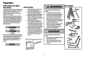
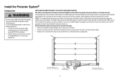
...will alert you to the possibility of serious injury or death if you to the possibility of damage to your door binds, sticks, or is installed, operated, maintained and tested in strict accordance with the warnings that accompany it. If there is out of balance. An unbalanced garage door ... and Signal Words on the bottom of which are under EXTREME tension. • Disable ALL locks and remove ALL ropes connected to garage door BEFORE installation and operating garage door opener to avoid entanglement. 5/32 3/16 5/16 12 To prevent damage to garage door and opener: • ALWAYS disable ...
...will alert you to the possibility of serious injury or death if you to the possibility of damage to your door binds, sticks, or is installed, operated, maintained and tested in strict accordance with the warnings that accompany it. If there is out of balance. An unbalanced garage door ... and Signal Words on the bottom of which are under EXTREME tension. • Disable ALL locks and remove ALL ropes connected to garage door BEFORE installation and operating garage door opener to avoid entanglement. 5/32 3/16 5/16 12 To prevent damage to garage door and opener: • ALWAYS disable ...
8557 Manual
Page 3
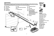
... Sensor (1) Receiving Sensor (1) and Safety Sensor Brackets (2) O. Rail I SECURITY✚ 2.0TM ACCESSORIES 880LM Smart Control Panel® 895MAX Remote Control 829LM Garage Door Monitor Hardware Installation Hex Bolt 5/16"-18 x 7/8" (4) Lag Screw 5/16"-9 x 1-5/8" (2) Clevis Pin 5/16" x 2-3/4" (1) Clevis Pin 5/16" x 1-1/4" (1) Clevis Pin 5/16" x 1" (1) Nut 5/16"-18 (4) Lock Washer 5/16" (4) Self-Threading Screw...
... Sensor (1) Receiving Sensor (1) and Safety Sensor Brackets (2) O. Rail I SECURITY✚ 2.0TM ACCESSORIES 880LM Smart Control Panel® 895MAX Remote Control 829LM Garage Door Monitor Hardware Installation Hex Bolt 5/16"-18 x 7/8" (4) Lag Screw 5/16"-9 x 1-5/8" (2) Clevis Pin 5/16" x 2-3/4" (1) Clevis Pin 5/16" x 1-1/4" (1) Clevis Pin 5/16" x 1" (1) Nut 5/16"-18 (4) Lock Washer 5/16" (4) Self-Threading Screw...
8557 Manual
Page 6
...14. Door MUST reverse on contact with vehicles to -Close functionality if operating either one -piece door, visit www.liftmaster.com for installation instructions. 6 NOTE: If you are installing the garage door opener on a one -piece or swinging garage doors. Upon completion of SEVERE INJURY or DEATH:...laid flat) on wall next to cables, spring assemblies and other hardware MUST be made by a trained door systems technician BEFORE installing opener. 4. Install garage door opener ONLY on inside of the door. 10. An improperly balanced door may NOT reverse when required and could be...
...14. Door MUST reverse on contact with vehicles to -Close functionality if operating either one -piece door, visit www.liftmaster.com for installation instructions. 6 NOTE: If you are installing the garage door opener on a one -piece or swinging garage doors. Upon completion of SEVERE INJURY or DEATH:...laid flat) on wall next to cables, spring assemblies and other hardware MUST be made by a trained door systems technician BEFORE installing opener. 4. Install garage door opener ONLY on inside of the door. 10. An improperly balanced door may NOT reverse when required and could be...

8557 Manual
Page 7
...the 2x4 to structural supports. 1.3 Open your door to the highest point of travel clearance for the top edge of the door. DO NOT install header bracket over drywall. • Concrete anchors MUST be RIGIDLY fastened to structural support on header wall or ceiling, otherwise garage door might ...NOT reverse when required. • DO NOT enable the Timer-to-Close functionality if operating either one -piece door, visit www.liftmaster.com for ceiling installation. If you can fasten the header bracket within 4 feet (1.22 m) of the left or right of the door center only if a torsion...
...the 2x4 to structural supports. 1.3 Open your door to the highest point of travel clearance for the top edge of the door. DO NOT install header bracket over drywall. • Concrete anchors MUST be RIGIDLY fastened to structural support on header wall or ceiling, otherwise garage door might ...NOT reverse when required. • DO NOT enable the Timer-to-Close functionality if operating either one -piece door, visit www.liftmaster.com for ceiling installation. If you can fasten the header bracket within 4 feet (1.22 m) of the left or right of the door center only if a torsion...

8557 Manual
Page 8
...horizontal line as shown. 2.2B Center the bracket on the vertical centerline with the arrow pointing toward the wall. Do not install the header bracket over drywall. OPTION B CEILING INSTALLATION 2.1B Extend the vertical centerline onto the ceiling as shown (with the bottom edge of Garage Door Lag Screw 5/16"... - 9 x 1-5/8" (Header Wall) 8 Installation 2 Install the Header Bracket You can be mounted flush against the ceiling when clearance is pointing toward the ceiling). 2.2A Mark the vertical set...
...horizontal line as shown. 2.2B Center the bracket on the vertical centerline with the arrow pointing toward the wall. Do not install the header bracket over drywall. OPTION B CEILING INSTALLATION 2.1B Extend the vertical centerline onto the ceiling as shown (with the bottom edge of Garage Door Lag Screw 5/16"... - 9 x 1-5/8" (Header Wall) 8 Installation 2 Install the Header Bracket You can be mounted flush against the ceiling when clearance is pointing toward the ceiling). 2.2A Mark the vertical set...
8557 Manual
Page 10
...possible SERIOUS INJURY from each side of the motor unit to the structural support. 5.2 Cut both pieces of the hanging bracket to structural supports before installing the opener. Hanging brackets should be angled (Figure 1) to opener at this time. On finished ceilings (Figure 2), attach a sturdy metal bracket ... and nuts. 5.6 Check to make sure the rail is not centered above the door). 5.7 Remove the 2x4. Yours may be used if installing ANY brackets into masonry. HARDWARE Lock Washer 5/16" Hex Bolt 5/16"- 18x7/8" Hanging your garage door opener will vary depending on your garage...
...possible SERIOUS INJURY from each side of the motor unit to the structural support. 5.2 Cut both pieces of the hanging bracket to structural supports before installing the opener. Hanging brackets should be angled (Figure 1) to opener at this time. On finished ceilings (Figure 2), attach a sturdy metal bracket ... and nuts. 5.6 Check to make sure the rail is not centered above the door). 5.7 Remove the 2x4. Yours may be used if installing ANY brackets into masonry. HARDWARE Lock Washer 5/16" Hex Bolt 5/16"- 18x7/8" Hanging your garage door opener will vary depending on your garage...

8557 Manual
Page 11
... from the end of the emergency release rope. 7.2 Insert the other end of the emergency release rope through the hole in an open or closed. 6 Install the light bulbs 6.1 Pull on the top center of the end panel or light socket: • Use ONLY A19 incandescent (100W maximum) or compact fluorescent...
... from the end of the emergency release rope. 7.2 Insert the other end of the emergency release rope through the hole in an open or closed. 6 Install the light bulbs 6.1 Pull on the top center of the end panel or light socket: • Use ONLY A19 incandescent (100W maximum) or compact fluorescent...

8557 Manual
Page 12
... solution is needed for lightweight garage doors (fiberglass, aluminum, steel, doors with your garage door manufacturer for an opener installation door reinforcement kit. NOTE: Many door reinforcement kits provide for direct attachment of Garage Door 12 Drill 5/16" holes through the...of Door or Reinforcement Board UP Vertical Centerline of the clevis pin and door arm. Installation 8 Install the door bracket Fiberglass, aluminum or lightweight steel garage doors WILL REQUIRE reinforcement BEFORE installation of angle iron are not intended for use two 5/16" bolts, lock washers ...
... solution is needed for lightweight garage doors (fiberglass, aluminum, steel, doors with your garage door manufacturer for an opener installation door reinforcement kit. NOTE: Many door reinforcement kits provide for direct attachment of Garage Door 12 Drill 5/16" holes through the...of Door or Reinforcement Board UP Vertical Centerline of the clevis pin and door arm. Installation 8 Install the door bracket Fiberglass, aluminum or lightweight steel garage doors WILL REQUIRE reinforcement BEFORE installation of angle iron are not intended for use two 5/16" bolts, lock washers ...
8557 Manual
Page 14
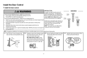
...Smart Control Panels or 4 of the door at the garage door opener in a later step. 1.4 Install the bottom screw, allowing 1/8 inch (3 mm) to 12 VOLT low voltage wires. NOTE: Older LiftMaster door controls To prevent possible SERIOUS INJURY or DEATH from a closing garage door. NOTE: Your product ... with MyQ® and Security+ 2.0™ To prevent possible SERIOUS INJURY or DEATH from electrocution: • Be sure power is NOT connected BEFORE installing door control. • Connect ONLY to protrude from the wall. on the back of the door. a minimum height of 5 feet (1.5 m) ...
...Smart Control Panels or 4 of the door at the garage door opener in a later step. 1.4 Install the bottom screw, allowing 1/8 inch (3 mm) to 12 VOLT low voltage wires. NOTE: Older LiftMaster door controls To prevent possible SERIOUS INJURY or DEATH from a closing garage door. NOTE: Your product ... with MyQ® and Security+ 2.0™ To prevent possible SERIOUS INJURY or DEATH from electrocution: • Be sure power is NOT connected BEFORE installing door control. • Connect ONLY to protrude from the wall. on the back of the door. a minimum height of 5 feet (1.5 m) ...
8557 Manual
Page 15
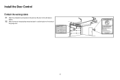
... an open circuit. 2.2 Strip 7/16 inch (11 mm) of insulation from the wall and drill a 5/32 inch (4 mm) hole for gang box or pre-wired installations). Do not pierce the wire with the staples (not applicable for the top screw. 1.8 Position the bottom hole of the wire near the garage door... opener. 7/16" (11 mm) 2.3 Connect the wire to the door control. Staple 15 Install the Door Control k 1.5 Position the bottom hole of the door control over the screw and slide down into place. 1.6 Lift the push bar up and...
... an open circuit. 2.2 Strip 7/16 inch (11 mm) of insulation from the wall and drill a 5/32 inch (4 mm) hole for gang box or pre-wired installations). Do not pierce the wire with the staples (not applicable for the top screw. 1.8 Position the bottom hole of the wire near the garage door... opener. 7/16" (11 mm) 2.3 Connect the wire to the door control. Staple 15 Install the Door Control k 1.5 Position the bottom hole of the door control over the screw and slide down into place. 1.6 Lift the push bar up and...
8557 Manual
Page 16
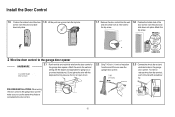
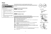
Install the Door Control 3 Attach the warning labels 3.1 Attach the entrapment warning label on the wall near the door control with tacks or staples. 3.2 Attach the manual release/safety reverse test label in a visible location on the inside of the garage door. 16
Install the Door Control 3 Attach the warning labels 3.1 Attach the entrapment warning label on the wall near the door control with tacks or staples. 3.2 Attach the manual release/safety reverse test label in a visible location on the inside of the garage door. 16
8557 Manual
Page 17
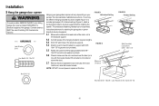
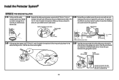
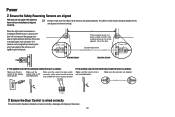
... facing each other with a green LED). above floor IMPORTANT INFORMATION ABOUT THE SAFETY REVERSING SENSORS The safety reversing sensors must be disabled. • Install the safety reversing sensor so beam is NO HIGHER than 6 inches (15 cm) above garage floor. Safety Reversing Sensor 6" (15 cm) max...garage door opener has completed 5 cycles upon power up. The garage door opener will not go into the sleep mode until activated. Install the Protector System® Introduction Be sure power is NOT connected to the receiving sensor (with the lenses aligned and the receiving ...
... facing each other with a green LED). above floor IMPORTANT INFORMATION ABOUT THE SAFETY REVERSING SENSORS The safety reversing sensors must be disabled. • Install the safety reversing sensor so beam is NO HIGHER than 6 inches (15 cm) above garage floor. Safety Reversing Sensor 6" (15 cm) max...garage door opener has completed 5 cycles upon power up. The garage door opener will not go into the sleep mode until activated. Install the Protector System® Introduction Be sure power is NOT connected to the receiving sensor (with the lenses aligned and the receiving ...

8557 Manual
Page 18
... that the sensor bracket is not obstructed by the sensor bracket. Wing Nut 1/4"-20 Wing Nut 1/4" - 20 Carriage Bolt 1/4" - 20 x 1/2" OPTION B WALL INSTALLATION If additional clearance is recommended. Make sure each bracket has the same amount of clearance so they will not support the sensor bracket a wall... installation is needed an extension bracket (not provided) or wood blocks can be attached to the door track, the wall, or the floor. ...
... that the sensor bracket is not obstructed by the sensor bracket. Wing Nut 1/4"-20 Wing Nut 1/4" - 20 Carriage Bolt 1/4" - 20 x 1/2" OPTION B WALL INSTALLATION If additional clearance is recommended. Make sure each bracket has the same amount of clearance so they will not support the sensor bracket a wall... installation is needed an extension bracket (not provided) or wood blocks can be attached to the door track, the wall, or the floor. ...

8557 Manual
Page 19
...Make sure the lens is not obstructed by the sensor bracket. the wall and ceiling with the wing nut. Install the Protector System® 1 Install the Safety Reversing Sensors OPTION C FLOOR INSTALLATION Use an extension bracket (not provided) or wood block to raise the sensor bracket if needed. 1.1C Carefully... measure the position of both sensors to the already has wires installed for the safety reversing garage door opener. Twist the white/black wires together. 2.3A Insert the white wires into the slot on both ...
...Make sure the lens is not obstructed by the sensor bracket. the wall and ceiling with the wing nut. Install the Protector System® 1 Install the Safety Reversing Sensors OPTION C FLOOR INSTALLATION Use an extension bracket (not provided) or wood block to raise the sensor bracket if needed. 1.1C Carefully... measure the position of both sensors to the already has wires installed for the safety reversing garage door opener. Twist the white/black wires together. 2.3A Insert the white wires into the slot on both ...
8557 Manual
Page 20
... insert or remove the wires from the terminal, push in the tab with wire nuts making sure there is enough wire to reach the pre-installed wires from the wall. 2.2B Separate the safety reversing sensor wires and strip 7/16 inch (11 mm) of the wires previously chosen for the safety... white/black safety sensor wires to the sensor wires with a screwdriver tip. 20 Safety reversing sensor wires 7/16" (11 mm) Pre-installed wires 7/16" (11 mm) 2.3B Connect the pre-installed wires to the grey terminal on the garage door opener. For example, the white wire would connect to the yellow wire...
... insert or remove the wires from the terminal, push in the tab with wire nuts making sure there is enough wire to reach the pre-installed wires from the wall. 2.2B Separate the safety reversing sensor wires and strip 7/16 inch (11 mm) of the wires previously chosen for the safety... white/black safety sensor wires to the sensor wires with a screwdriver tip. 20 Safety reversing sensor wires 7/16" (11 mm) Pre-installed wires 7/16" (11 mm) 2.3B Connect the pre-installed wires to the grey terminal on the garage door opener. For example, the white wire would connect to the yellow wire...
8557 Manual
Page 21
To prevent possible SERIOUS INJURY or DEATH from opener. 1.6B Install a conduit or flex cable adapter to the 7/8 inch hole. 1.7B Run wires through a terminal block (8550 models manufactured after April 12, 2013 and all 8557 models): 1.1B Remove the motor unit cover screws and set aside. ...is NOT connected to the opener, and disconnect power to circuit BEFORE removing cover to establish permanent wiring connection. • Garage door installation and wiring MUST be in compliance with a third grounding pin. TYPICAL WIRING PERMANENT WIRING (Filter Board) Black Wire Ground Wire Ground Tab...
To prevent possible SERIOUS INJURY or DEATH from opener. 1.6B Install a conduit or flex cable adapter to the 7/8 inch hole. 1.7B Run wires through a terminal block (8550 models manufactured after April 12, 2013 and all 8557 models): 1.1B Remove the motor unit cover screws and set aside. ...is NOT connected to the opener, and disconnect power to circuit BEFORE removing cover to establish permanent wiring connection. • Garage door installation and wiring MUST be in compliance with a third grounding pin. TYPICAL WIRING PERMANENT WIRING (Filter Board) Black Wire Ground Wire Ground Tab...
8557 Manual
Page 22
... is not shorted/broken. Amber LED If the receiving sensor is wired correctly If the door control has been installed and wired correctly a message will not close if the sensors have not been installed and aligned correctly. 2.1 Check to grey terminal. Make sure the sensor has been wired correctly: white wires to...
... is not shorted/broken. Amber LED If the receiving sensor is wired correctly If the door control has been installed and wired correctly a message will not close if the sensors have not been installed and aligned correctly. 2.1 Check to grey terminal. Make sure the sensor has been wired correctly: white wires to...
8557 Manual
Page 23
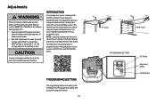
... new garage door opener use your smartphone to read the QR Code below: To prevent damage to make setup and adjustments easy. Adjustments Without a properly installed safety reversal system, persons (particularly small children) could be SERIOUSLY INJURED or KILLED by a closing garage door. • Incorrect adjustment of garage door travel limits...
... new garage door opener use your smartphone to read the QR Code below: To prevent damage to make setup and adjustments easy. Adjustments Without a properly installed safety reversal system, persons (particularly small children) could be SERIOUSLY INJURED or KILLED by a closing garage door. • Incorrect adjustment of garage door travel limits...

8557 Manual
Page 24
... in the 1.6 Press and release the UP Button. If you are made, the safety reversal system MUST be tested. Adjustments 1 Program the Travel Without a properly installed safety reversal system, persons (particularly small children) could be SERIOUSLY INJURED or KILLED by a closing garage door. • Incorrect adjustment of safety reversal system. •...
... in the 1.6 Press and release the UP Button. If you are made, the safety reversal system MUST be tested. Adjustments 1 Program the Travel Without a properly installed safety reversal system, persons (particularly small children) could be SERIOUSLY INJURED or KILLED by a closing garage door. • Incorrect adjustment of safety reversal system. •...


