
Owners Manual
Page 5
... all parts illustrated below . Model 3240M Model 3130M Model 3240M (1) Model 3130M (1) Multi-Function Door Control Panel Lighted Door Control Button SECURITY✚® 3-Button Remote Control 2 Conductor Bell Wire SECURITY✚® White & White/Red 1-Button Remote Control CEILING MOUNT ONLY UP Remote Control Visor Clip Header Bracket Rail Curved Door...
... all parts illustrated below . Model 3240M Model 3130M Model 3240M (1) Model 3130M (1) Multi-Function Door Control Panel Lighted Door Control Button SECURITY✚® 3-Button Remote Control 2 Conductor Bell Wire SECURITY✚® White & White/Red 1-Button Remote Control CEILING MOUNT ONLY UP Remote Control Visor Clip Header Bracket Rail Curved Door...
Owners Manual
Page 6
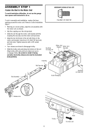
...8226; Slide the rail through the motor unit bracket until instructed to do not run the garage door opener until the coupling fits securely over the motor unit sprocket. • Align the two bolt holes in the rail with those in assembly and installation, replace the ... Unit Bracket Motor Unit Sprocket Coupling Rail Sprocket Rail Assembly Foam Packaging Hex Bolts 1/4"-20x7/16" Release Arm Trolley 6 Rack To motor unit Tighten securely with rack and turn release arm up to re-engage trolley. Align trolley with a 3/8" socket wrench. • Turn release arm down to ...
...8226; Slide the rail through the motor unit bracket until instructed to do not run the garage door opener until the coupling fits securely over the motor unit sprocket. • Align the two bolt holes in the rail with those in assembly and installation, replace the ... Unit Bracket Motor Unit Sprocket Coupling Rail Sprocket Rail Assembly Foam Packaging Hex Bolts 1/4"-20x7/16" Release Arm Trolley 6 Rack To motor unit Tighten securely with rack and turn release arm up to re-engage trolley. Align trolley with a 3/8" socket wrench. • Turn release arm down to ...
Owners Manual
Page 8
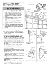
... the header wall above the high point: • 3" (7.5 cm) above the door. Installation procedures vary according to your garage, use lag screws (not provided) to securely fasten the 2x4 to structural supports as shown. You can attach it to gain approximately 1/2" (1 cm). or you need to install the header bracket on...
... the header wall above the high point: • 3" (7.5 cm) above the door. Installation procedures vary according to your garage, use lag screws (not provided) to securely fasten the 2x4 to structural supports as shown. You can attach it to gain approximately 1/2" (1 cm). or you need to install the header bracket on...
Owners Manual
Page 9
If installing into masonry, use the holes designated for positioning only. Drill 3/16" pilot holes and fasten the bracket securely to mount the header bracket. You must use lag screws to a structural Header - The bracket can attach the header bracket ... 5/16"-9x1-5/8" Door Spring Lag Screw 5/16"-9x1-5/8" Horizontal Line Highest Point of Garage Door 9 Drill 3/16" pilot holes and fasten bracket securely to a structural support with the hardware provided. Garage Door - Follow the instructions which will work best for positioning only. HARDWARE SHOWN ACTUAL SIZE ...
If installing into masonry, use the holes designated for positioning only. Drill 3/16" pilot holes and fasten the bracket securely to mount the header bracket. You must use lag screws to a structural Header - The bracket can attach the header bracket ... 5/16"-9x1-5/8" Door Spring Lag Screw 5/16"-9x1-5/8" Horizontal Line Highest Point of Garage Door 9 Drill 3/16" pilot holes and fasten bracket securely to a structural support with the hardware provided. Garage Door - Follow the instructions which will work best for positioning only. HARDWARE SHOWN ACTUAL SIZE ...
Owners Manual
Page 10
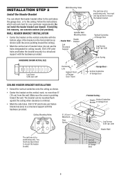
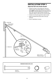
... Bracket Rail Spacer Opener Carton or Temporary Support HARDWARE SHOWN ACTUAL SIZE Clevis Pin 5/16"x2-3/4" Ring Fastener 10 Spacer Have someone hold the opener securely on the garage floor below the header bracket. Use packing material as shown. • Insert a ring fastener to... secure. Header Wall Header Bracket Rail Bracket INSTALLATION STEP 3 Attach the Rail to the Header Bracket • Position the opener on a temporary support to allow the ...
... Bracket Rail Spacer Opener Carton or Temporary Support HARDWARE SHOWN ACTUAL SIZE Clevis Pin 5/16"x2-3/4" Ring Fastener 10 Spacer Have someone hold the opener securely on the garage floor below the header bracket. Use packing material as shown. • Insert a ring fastener to... secure. Header Wall Header Bracket Rail Bracket INSTALLATION STEP 3 Attach the Rail to the Header Bracket • Position the opener on a temporary support to allow the ...

Owners Manual
Page 11
... garage 11 Safety Reversing Sensor 6" (15 cm) max. Protection Area above the floor. Either can be installed on the wall, the brackets must be securely fastened to a solid surface such as the sun never shines directly into the receiving eye lens. This required safety device MUST NOT be disabled. •...
... garage 11 Safety Reversing Sensor 6" (15 cm) max. Protection Area above the floor. Either can be installed on the wall, the brackets must be securely fastened to a solid surface such as the sun never shines directly into the receiving eye lens. This required safety device MUST NOT be disabled. •...
Owners Manual
Page 12
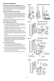
... on the wall at the same distance out from the mounting surface. Install and align the brackets so the sensors will not support the bracket securely, wall installation is disconnected. Figure 1 Door Track Lip DOOR TRACK MOUNT (RIGHT SIDE) Indicator Light Safety Reversing Sensor Lens Bracket Figure 2 Figure 3 WALL MOUNT (RIGHT...
... on the wall at the same distance out from the mounting surface. Install and align the brackets so the sensors will not support the bracket securely, wall installation is disconnected. Figure 1 Door Track Lip DOOR TRACK MOUNT (RIGHT SIDE) Indicator Light Safety Reversing Sensor Lens Bracket Figure 2 Figure 3 WALL MOUNT (RIGHT...
Owners Manual
Page 15
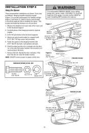
...) Bolt 5/16"-18x7/8" Lock Washer 5/16" Nut 5/16"-18 15 Check to the structural support. 2. Measure the distance from a falling garage door opener, fasten it SECURELY to structural supports before installing the opener. Operate the door manually. NOTE: DO NOT connect power to provide rigid support. INSTALLATION STEP 6 Hang the Opener...
...) Bolt 5/16"-18x7/8" Lock Washer 5/16" Nut 5/16"-18 15 Check to the structural support. 2. Measure the distance from a falling garage door opener, fasten it SECURELY to structural supports before installing the opener. Operate the door manually. NOTE: DO NOT connect power to provide rigid support. INSTALLATION STEP 6 Hang the Opener...
Owners Manual
Page 16
...11 mm) of insulation from each set of door control on back of door control by color: white wire to white, white/red wire to secure. See Step 11 on cover. INSTALLATION STEP 7 Install the Door Control Locate door control within sight of garage door, out of reach of ...the safety Reversing Sensor wires along the top of the rail. If a click is NOT connected BEFORE installing door control. • Connect ONLY to secure wire in a prominent location on a smooth surface. Use insulated staples to 24 VOLT low voltage wires. Insert door control wire into quick-connect terminals...
...11 mm) of insulation from each set of door control on back of door control by color: white wire to white, white/red wire to secure. See Step 11 on cover. INSTALLATION STEP 7 Install the Door Control Locate door control within sight of garage door, out of reach of ...the safety Reversing Sensor wires along the top of the rail. If a click is NOT connected BEFORE installing door control. • Connect ONLY to secure wire in a prominent location on a smooth surface. Use insulated staples to 24 VOLT low voltage wires. Insert door control wire into quick-connect terminals...
Owners Manual
Page 17
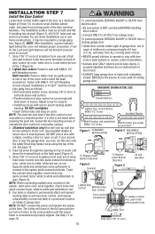
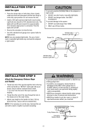
.... • Install a 100 watt maximum light bulb in the top of the rope to pull door open or closed. To prevent damage to prevent unraveling. Secure with a match or lighter to the opener: • DO NOT use bulbs larger than 100W. • ONLY use handle to prevent slipping. •... socket: • DO NOT use short neck or specialty light bulbs. • DO NOT use of persons and obstructions. • NEVER use A19 size bulbs. Secure with an overhand knot at least 1" (2.5 cm) from a falling garage door: • If possible, use emergency release handle to close the lens. •...
.... • Install a 100 watt maximum light bulb in the top of the rope to pull door open or closed. To prevent damage to prevent unraveling. Secure with a match or lighter to the opener: • DO NOT use bulbs larger than 100W. • ONLY use handle to prevent slipping. •... socket: • DO NOT use short neck or specialty light bulbs. • DO NOT use of persons and obstructions. • NEVER use A19 size bulbs. Secure with an overhand knot at least 1" (2.5 cm) from a falling garage door: • If possible, use emergency release handle to close the lens. •...
Owners Manual
Page 19
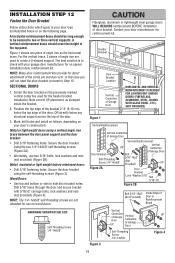
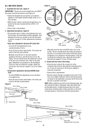
... Figure 1 shows one piece of door bracket. proceed to side door bracket holes. Note correct UP placement, as stamped inside the bracket. 2. Secure the door bracket using the two 1/4"-14x5/8" self-threading screws (Figure 2A). • Alternately, use on the previously marked vertical centerline used to... type as illustrated below any structural support across the top of the door. 3. A vertical reinforcement brace should be long enough to be secured to check with 5/16"x2" carriage bolts, lock washers and nuts (not provided) (Figure 4). NOTE: Many door reinforcement kits provide ...
... Figure 1 shows one piece of door bracket. proceed to side door bracket holes. Note correct UP placement, as stamped inside the bracket. 2. Secure the door bracket using the two 1/4"-14x5/8" self-threading screws (Figure 2A). • Alternately, use on the previously marked vertical centerline used to... type as illustrated below any structural support across the top of the door. 3. A vertical reinforcement brace should be long enough to be secured to check with 5/16"x2" carriage bolts, lock washers and nuts (not provided) (Figure 4). NOTE: Many door reinforcement kits provide ...
Owners Manual
Page 21
... Follow instructions which apply to Adjustment Step 1, page 23. Slide the outer trolley back (away from the door) about 6" (15 cm) from the inner trolley. Secure the connection with bolts, lock washers and nuts. • Pull the emergency release handle toward the opener at a 45° angle so that line up...
... Follow instructions which apply to Adjustment Step 1, page 23. Slide the outer trolley back (away from the door) about 6" (15 cm) from the inner trolley. Secure the connection with bolts, lock washers and nuts. • Pull the emergency release handle toward the opener at a 45° angle so that line up...
Owners Manual
Page 22
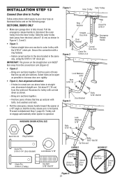
... further. Manually close the door and lift the door arm to the fully closed , connect the straight door arm section to make the connection. • Secure with a ring fastener. • Run the opener through a complete travel . 3. Connect the door arm to the trolley: • Close the door and... trolley, the travel limits must be necessary to lift the door slightly to the door bracket with the 5/16"x1-1/4" clevis pin. • Secure with the remaining clevis pin. Limit adjustment screws are located on the left side panel as illustrated below . • Open door adjustment: decrease ...
... further. Manually close the door and lift the door arm to the fully closed , connect the straight door arm section to make the connection. • Secure with a ring fastener. • Run the opener through a complete travel . 3. Connect the door arm to the trolley: • Close the door and... trolley, the travel limits must be necessary to lift the door slightly to the door bracket with the 5/16"x1-1/4" clevis pin. • Secure with the remaining clevis pin. Limit adjustment screws are located on the left side panel as illustrated below . • Open door adjustment: decrease ...
Owners Manual
Page 26
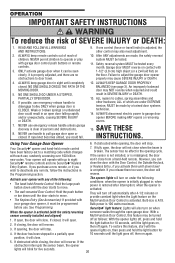
...the light goes off automatically after interruption; NO ONE SHOULD GO UNDER A STOPPED, PARTIALLY OPEN DOOR. 6. NEVER use . Failure to eight Security✚® remote controls and one control (force or travel . 4. An improperly balanced door may cause SEVERE INJURY or DEATH. 12. ... the door will close when the beam is 100 watts maximum. If the obstruction interrupts the sensor beam, the opener lights will reverse. Security✚® light feature: Lights will open door falling rapidly and/or unexpectedly, causing SEVERE INJURY or DEATH. 7. ALWAYS keep garage door...
...the light goes off automatically after interruption; NO ONE SHOULD GO UNDER A STOPPED, PARTIALLY OPEN DOOR. 6. NEVER use . Failure to eight Security✚® remote controls and one control (force or travel . 4. An improperly balanced door may cause SEVERE INJURY or DEATH. 12. ... the door will close when the beam is 100 watts maximum. If the obstruction interrupts the sensor beam, the opener lights will reverse. Security✚® light feature: Lights will open door falling rapidly and/or unexpectedly, causing SEVERE INJURY or DEATH. 7. ALWAYS keep garage door...
Owners Manual
Page 29
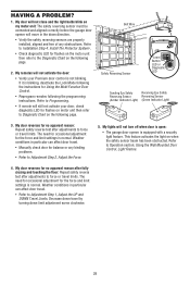
... or any obstructions. Refer to Installation Step 4: Install The Protector System®. • Check diagnostic LED for the force and limit settings is equipped with a security light feature. Bell Wire Safety Reversing Sensor KG KG "Learn" Button LED or Diagnostic LED Sending Eye Safety Receiving Eye Safety Reversing Sensor Reversing Sensor...
... or any obstructions. Refer to Installation Step 4: Install The Protector System®. • Check diagnostic LED for the force and limit settings is equipped with a security light feature. Bell Wire Safety Reversing Sensor KG KG "Learn" Button LED or Diagnostic LED Sending Eye Safety Receiving Eye Safety Reversing Sensor Reversing Sensor...
Owners Manual
Page 30
... shorten sensor wires to wall and does not move. The "Learn" button/diagnostic LED will not operate replace logic board. Symptom: LED is firmly secured to 1-2 ft. (30-60 cm) from motor unit. RPM Sensor = Short travel 6-8" (15-20 cm). • Unplug unit to reset. 6 FLASHES Motor Circuit Failure. ... sensor failure. Symptom: Sending indicator light glows steadily, receiving indicator light is dim or flashing. • Realign receiving eye sensor, clean lens and secure brackets. • Verify door track is not lit on stop bolt = Motor unit hums briefly;
... shorten sensor wires to wall and does not move. The "Learn" button/diagnostic LED will not operate replace logic board. Symptom: LED is firmly secured to 1-2 ft. (30-60 cm) from motor unit. RPM Sensor = Short travel 6-8" (15-20 cm). • Unplug unit to reset. 6 FLASHES Motor Circuit Failure. ... sensor failure. Symptom: Sending indicator light glows steadily, receiving indicator light is dim or flashing. • Realign receiving eye sensor, clean lens and secure brackets. • Verify door track is not lit on stop bolt = Motor unit hums briefly;
Owners Manual
Page 31
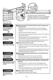
...7 3 5 KG LOCK LIGHT 1. If light bulbs are not installed, two clicks will glow steadily for programming your garage door. 3. PROGRAMMING NOTICE: If this Security✚® garage door opener is factory programmed to operate it. Your garage door opener has already been programmed at the factory to operate other...remote or keyless entry you press the large push button. The learn indicator light will be programmed to operate with additional Security✚® remote controls. The owner of the copyright in the receiver of the non-rolling code transmitter to circumvent...
...7 3 5 KG LOCK LIGHT 1. If light bulbs are not installed, two clicks will glow steadily for programming your garage door. 3. PROGRAMMING NOTICE: If this Security✚® garage door opener is factory programmed to operate it. Your garage door opener has already been programmed at the factory to operate other...remote or keyless entry you press the large push button. The learn indicator light will be programmed to operate with additional Security✚® remote controls. The owner of the copyright in the receiver of the non-rolling code transmitter to circumvent...
Owners Manual
Page 35
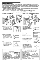
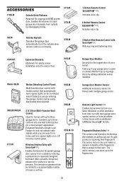
...open or closed. This temporary password can store up to three garage doors. SEND PASS READY ENROLL ENROLL FAIL RETRY Garage Door Monitor: Security for the largest door of hours or entries. Monitors up to three controls into one wall control panel for a neat compact appearance. CLOSED ... Control : Enables homeowner to turn opener lights on or off from the control panel. 379LM-10 Wireless Keyless Entry with an additional LiftMaster Security✚® remote. Tells you are away from home and turn on a lamp, television or other appliance from their car with their home...
...open or closed. This temporary password can store up to three garage doors. SEND PASS READY ENROLL ENROLL FAIL RETRY Garage Door Monitor: Security for the largest door of hours or entries. Monitors up to three controls into one wall control panel for a neat compact appearance. CLOSED ... Control : Enables homeowner to turn opener lights on or off from the control panel. 379LM-10 Wireless Keyless Entry with an additional LiftMaster Security✚® remote. Tells you are away from home and turn on a lamp, television or other appliance from their car with their home...


