
User's Guide
Page 121
...PURPOSE, AND SATISFACTORY QUALITY. To obtain warranty service, you may not be available or only be available for repair or replacement (at http://support.lexmark.com. To obtain warranty service you may be required to deliver your area, contact on the World Wide Web...contents, are substantially used with the product for exchange is defaced, altered, in need of a repair not included in transit to present the feature or option with Lexmark user's guides, manuals, instructions or guidance. • Unsuitable physical or operating environment • Maintenance by anyone other ...
...PURPOSE, AND SATISFACTORY QUALITY. To obtain warranty service, you may not be available or only be available for repair or replacement (at http://support.lexmark.com. To obtain warranty service you may be required to deliver your area, contact on the World Wide Web...contents, are substantially used with the product for exchange is defaced, altered, in need of a repair not included in transit to present the feature or option with Lexmark user's guides, manuals, instructions or guidance. • Unsuitable physical or operating environment • Maintenance by anyone other ...
Service Manual
Page 20
... and removing and installing FRUs. 5. Repair information provides instructions for service personnel. Connector locations uses illustrations to perform the task. Warning: A warning identifies something that might cause a servicer harm. xx Service Manual Parts catalog contains illustrations and part numbers... field replaceable units (FRUs). 3. Diagnostic information contains an error indicator table, symptom tables, and service checks used to repair it. Diagnostic aids contains tests and checks used to prevent problems. 7. It is a danger from hazardous voltage in ...
... and removing and installing FRUs. 5. Repair information provides instructions for service personnel. Connector locations uses illustrations to perform the task. Warning: A warning identifies something that might cause a servicer harm. xx Service Manual Parts catalog contains illustrations and part numbers... field replaceable units (FRUs). 3. Diagnostic information contains an error indicator table, symptom tables, and service checks used to repair it. Diagnostic aids contains tests and checks used to prevent problems. 7. It is a danger from hazardous voltage in ...
Service Manual
Page 21
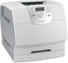
... 500-sheet paper trays of 32MB and 64MB • Hard disk-20GB+ with adapter • Integrated network options - Ethernet - Envelope feeder General information 1-1 MarkNet™ Print Servers - Lexmark PrintCryption™ card - 4061-xx0 1. The Lexmark T64x laser printers are not available in this manual leads you complete the repair, perform tests as needed to the correct...
... 500-sheet paper trays of 32MB and 64MB • Hard disk-20GB+ with adapter • Integrated network options - Ethernet - Envelope feeder General information 1-1 MarkNet™ Print Servers - Lexmark PrintCryption™ card - 4061-xx0 1. The Lexmark T64x laser printers are not available in this manual leads you complete the repair, perform tests as needed to the correct...
Service Manual
Page 94
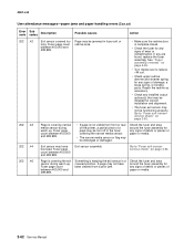
...Description Possible causes Action 202 .02 202 .03 Exit sensor covered too long. Go to "Fuser exit sensor service check" on page 2-92. Repair the redrive as necessary. • Check any installed output options(s) that may be installed for correct installation and alignment. • The fuser ...Go to reduce +W curl. • Check upper redrive diverter and diverter spring for any signs of a piece of paper or media. 2-54 Service Manual Fuser page count between 0 and 99,999. Narrow media sensor or flag may be jammed in fuser exit or redrive area. • Make sure...
...Description Possible causes Action 202 .02 202 .03 Exit sensor covered too long. Go to "Fuser exit sensor service check" on page 2-92. Repair the redrive as necessary. • Check any installed output options(s) that may be installed for correct installation and alignment. • The fuser ...Go to reduce +W curl. • Check upper redrive diverter and diverter spring for any signs of a piece of paper or media. 2-54 Service Manual Fuser page count between 0 and 99,999. Narrow media sensor or flag may be jammed in fuser exit or redrive area. • Make sure...

Service Manual
Page 96
Page may be functioning properly. Repair the redrive as necessary. • Check any installed output options(s) that may be installed for correct installation and alignment. • The fuser exit sensor may ...,999. • If page is covering narrow media sensor during warm up . If any signs of debris or pieces of paper or media. 2-56 Service Manual Page is keeping the exit sensor in fuser exit or redrive area. • Make sure the redrive door is complete closed. • Check the fuser...
Page may be functioning properly. Repair the redrive as necessary. • Check any installed output options(s) that may be installed for correct installation and alignment. • The fuser exit sensor may ...,999. • If page is covering narrow media sensor during warm up . If any signs of debris or pieces of paper or media. 2-56 Service Manual Page is keeping the exit sensor in fuser exit or redrive area. • Make sure the redrive door is complete closed. • Check the fuser...

Service Manual
Page 98
.... • Turn media over to reduce +W curl. • Check upper redrive diverter and diverter spring for any signs of paper or media. 2-58 Service Manual Check the fuser and area around the fuser assembly for correct installation and alignment. • The fuser exit sensor may not be installed for any... or flag may not have bounced. Fuser page count between 200,000 and 299,999. • If page is not visible from a prior jam. Repair the redrive as necessary. • Check any signs of debris or pieces of damage, a loose spring, or binding parts. Page is keeping the exit...
.... • Turn media over to reduce +W curl. • Check upper redrive diverter and diverter spring for any signs of paper or media. 2-58 Service Manual Check the fuser and area around the fuser assembly for correct installation and alignment. • The fuser exit sensor may not be installed for any... or flag may not have bounced. Fuser page count between 200,000 and 299,999. • If page is not visible from a prior jam. Repair the redrive as necessary. • Check any signs of debris or pieces of damage, a loose spring, or binding parts. Page is keeping the exit...

Service Manual
Page 100
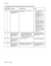
Fuser page count between 300,000 and 399,999. Repair the redrive as necessary. • Check any signs of debris or pieces of paper or media. Check the fuser and area around the fuser assembly ... may be functioning properly. Go to reduce +W curl. • Check upper redrive diverter and diverter spring for any signs of paper or media. 2-60 Service Manual Fuser page count between 300,000 and 399,999. • If page is not visible from a prior jam. A page may be jammed in the fuser...
Fuser page count between 300,000 and 399,999. Repair the redrive as necessary. • Check any signs of debris or pieces of paper or media. Check the fuser and area around the fuser assembly ... may be functioning properly. Go to reduce +W curl. • Check upper redrive diverter and diverter spring for any signs of paper or media. 2-60 Service Manual Fuser page count between 300,000 and 399,999. • If page is not visible from a prior jam. A page may be jammed in the fuser...
Service Manual
Page 102
... exit or redrive area. • Make sure the redrive door is complete closed. • Check the fuser for any signs of wear or contamination. Repair the redrive as necessary. • Check any installed output options(s) that may be installed for any signs of a page may be dislodged or damaged.... for any signs of debris or pieces of paper or media. If any signs of debris or pieces of paper or media. 2-62 Service Manual Check the fuser and area around the fuser assembly for correct installation and alignment. • The fuser exit sensor may be functioning properly. Page...
... exit or redrive area. • Make sure the redrive door is complete closed. • Check the fuser for any signs of wear or contamination. Repair the redrive as necessary. • Check any installed output options(s) that may be installed for any signs of a page may be dislodged or damaged.... for any signs of debris or pieces of paper or media. If any signs of debris or pieces of paper or media. 2-62 Service Manual Check the fuser and area around the fuser assembly for correct installation and alignment. • The fuser exit sensor may be functioning properly. Page...
Service Manual
Page 104
... fuser and area around the fuser assembly for any signs of debris or pieces of paper or media. 2-64 Service Manual Go to "Fuser exit sensor service check" on page 2-92. Repair the redrive as necessary. • Check any signs of a page may be torn off in fuser exit or redrive area...
... fuser and area around the fuser assembly for any signs of debris or pieces of paper or media. 2-64 Service Manual Go to "Fuser exit sensor service check" on page 2-92. Repair the redrive as necessary. • Check any signs of a page may be torn off in fuser exit or redrive area...

Service Manual
Page 106
... count is complete closed. • Check the fuser for any installed output options(s) that may be functioning properly. Repair the redrive as necessary. • Check any signs of paper or media. 2-66 Service Manual A page may not be jammed in a covered position. Go to reduce +W curl. • Check upper redrive diverter and...
... count is complete closed. • Check the fuser for any installed output options(s) that may be functioning properly. Repair the redrive as necessary. • Check any signs of paper or media. 2-66 Service Manual A page may not be jammed in a covered position. Go to reduce +W curl. • Check upper redrive diverter and...
Service Manual
Page 114
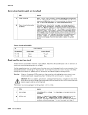
...DC motor is correctly installed at J2 on the cable connector. If correct, replace the mechanical linkage/ DC motor assembly. 2-74 Service Manual If this does not fix the problem, replace the control board. 271.xx Paper Jam - Make sure the solenoid is found, replace...linkage/DC motor assembly. J2-1 to J2-2 measures between 30 and 50 ohms. If incorrect, replace the failing solenoid assembly. If incorrect, repair as necessary. If incorrect, replace the mechanical linkage assembly/DC motor assembly. 990.xx Service Error displays FRU 1 Mechanical linkage DC motor assembly ...
...DC motor is correctly installed at J2 on the cable connector. If correct, replace the mechanical linkage/ DC motor assembly. 2-74 Service Manual If this does not fix the problem, replace the control board. 271.xx Paper Jam - Make sure the solenoid is found, replace...linkage/DC motor assembly. J2-1 to J2-2 measures between 30 and 50 ohms. If incorrect, replace the failing solenoid assembly. If incorrect, repair as necessary. If incorrect, replace the mechanical linkage assembly/DC motor assembly. 990.xx Service Error displays FRU 1 Mechanical linkage DC motor assembly ...
Service Manual
Page 120
... any other attached paper handling options. If the base printer operates correctly, go to "High-capacity feeder input tray service check" on page 4-1. If incorrect, repair as the switch is incorrect, inform the customer. Remove any installed option cards or assemblies. If the continuity changes as necessary. If incorrect, replace the... +1.0 V dc, replace the system board. If the line voltage is activated, replace the system board. If the voltage is correct, go to step 3. 2-80 Service Manual
... any other attached paper handling options. If the base printer operates correctly, go to "High-capacity feeder input tray service check" on page 4-1. If incorrect, repair as the switch is incorrect, inform the customer. Remove any installed option cards or assemblies. If the continuity changes as necessary. If incorrect, replace the... +1.0 V dc, replace the system board. If the line voltage is activated, replace the system board. If the voltage is correct, go to step 3. 2-80 Service Manual
Service Manual
Page 132
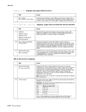
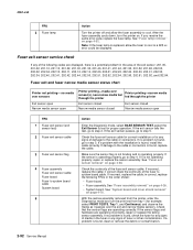
...or connectors is found, clean or remove the debris or contamination. 2-92 Service Manual See "Fuser exit sensor removal" on page 4-26. • System board. Check that the sensor flags are operating incorrectly, repair or replace the failing sensor assembly. Note: If the fuser lamp is operating... and hardware are operating correctly. If no problem is found, go to system board cable. If the sensor is not operating properly, repair or replace the sensor assembly. See "Fuser assembly removal" on page 4-28. Fuser exit and fuser narrow media sensor status chart Printer...
...or connectors is found, clean or remove the debris or contamination. 2-92 Service Manual See "Fuser exit sensor removal" on page 4-26. • System board. Check that the sensor flags are operating incorrectly, repair or replace the failing sensor assembly. Note: If the fuser lamp is operating... and hardware are operating correctly. If no problem is found, go to system board cable. If the sensor is not operating properly, repair or replace the sensor assembly. See "Fuser assembly removal" on page 4-28. Fuser exit and fuser narrow media sensor status chart Printer...
Service Manual
Page 136
...drive roll assembly and skewed backup roller for signs of paper actuating the pass thru sensor. If correct, replace the switch cable. 2-96 Service Manual 4061-xx0 FRU 4 High-capacity feeder option control board Action Check the voltage on the rollers. If incorrect, disconnect J8 from the input ...pin and the motor housing, replace the motor assembly. If incorrect, replace the switch. If incorrect, disconnect the cable at J9-1 (light blue). Repair or replace parts as necessary. If the voltage is full or has adequate paper in the tray FRU 1 Paper low switch Paper low switch cable...
...drive roll assembly and skewed backup roller for signs of paper actuating the pass thru sensor. If correct, replace the switch cable. 2-96 Service Manual 4061-xx0 FRU 4 High-capacity feeder option control board Action Check the voltage on the rollers. If incorrect, disconnect J8 from the input ...pin and the motor housing, replace the motor assembly. If incorrect, replace the switch. If incorrect, disconnect the cable at J9-1 (light blue). Repair or replace parts as necessary. If the voltage is full or has adequate paper in the tray FRU 1 Paper low switch Paper low switch cable...
Service Manual
Page 142
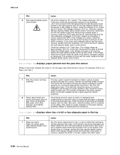
If incorrect, repair as the sensor flag is manually moved in the following order: • Autocompensator assembly option • Replace the option. 2-102 Service Manual The display changes from the sensor cable. Input tray(s) service check Optional 250-sheet and 500-sheet trays ...number of the front wiring harness. If correct, replace the input sensor assembly. If correct, make sure the lower pass thru sensor is found, repair as necessary. The voltage measures approximately +5 V dc. If incorrect, replace the harness. FRU 1 Input sensor flag 2 System board 3 Input...
If incorrect, repair as the sensor flag is manually moved in the following order: • Autocompensator assembly option • Replace the option. 2-102 Service Manual The display changes from the sensor cable. Input tray(s) service check Optional 250-sheet and 500-sheet trays ...number of the front wiring harness. If correct, replace the input sensor assembly. If correct, make sure the lower pass thru sensor is found, repair as necessary. The voltage measures approximately +5 V dc. If incorrect, replace the harness. FRU 1 Input sensor flag 2 System board 3 Input...
Service Manual
Page 146
... the system board and measure the voltage at a time. If this service check perform the "Button Test" on page 2-77. 2-106 Service Manual If the problem remains, replace the operator panel board (see "Operator panel board removal" on page 4-66. Disconnect the operator panel cable from J13...been installed in a printer, it can not be rendered inoperable. Before continuing with this procedure is not followed, the printer will be rendered inoperable. Repair using the button kit. See "Operator panel buttons removal" on page 4-78. If a 950.xx error code is found, replace the upper ...
... the system board and measure the voltage at a time. If this service check perform the "Button Test" on page 2-77. 2-106 Service Manual If the problem remains, replace the operator panel board (see "Operator panel board removal" on page 4-66. Disconnect the operator panel cable from J13...been installed in a printer, it can not be rendered inoperable. Before continuing with this procedure is not followed, the printer will be rendered inoperable. Repair using the button kit. See "Operator panel buttons removal" on page 4-78. If a 950.xx error code is found, replace the upper ...
Service Manual
Page 150
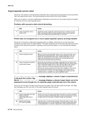
... Output expander assembly mechanical linkage Action Make sure the output expander option is the only option that is in the unrecognized expander option. Repair as being installed. If not, check the autoconnects of problem check the sub error codes. Check the cables at connector J6 on ...the output expander option. 202.xx Paper Jam Open Rear Door message displays; If incorrect, replace the output expander option. 2-110 Service Manual 4061-xx0 Output expander service check Service tip: The majority of the mechanical components can also occur prior to the output expander pass thru...
... Output expander assembly mechanical linkage Action Make sure the output expander option is the only option that is in the unrecognized expander option. Repair as being installed. If not, check the autoconnects of problem check the sub error codes. Check the cables at connector J6 on ...the output expander option. 202.xx Paper Jam Open Rear Door message displays; If incorrect, replace the output expander option. 2-110 Service Manual 4061-xx0 Output expander service check Service tip: The majority of the mechanical components can also occur prior to the output expander pass thru...

Service Manual
Page 154
If no problem is found , go to step 3. unable to step 2. It should measure approximately 0 ohms. 2-114 Service Manual Check for correct installation of the cable at J26 on the system board and ground. Check the continuity between J26-2 on the system board. If ... autosize fingers from activating the paper activate springs and ITC switches. 2 W S 1 W S 0 W S LGL A4 LTREXBE5C A5 2 Integrated card/ autocompensator cable 3 System board If a problem is found , repair or replace the tray assembly. 4061-xx0 Tray 1 not recognized as being installed;
If no problem is found , go to step 3. unable to step 2. It should measure approximately 0 ohms. 2-114 Service Manual Check for correct installation of the cable at J26 on the system board and ground. Check the continuity between J26-2 on the system board. If ... autosize fingers from activating the paper activate springs and ITC switches. 2 W S 1 W S 0 W S LGL A4 LTREXBE5C A5 2 Integrated card/ autocompensator cable 3 System board If a problem is found , repair or replace the tray assembly. 4061-xx0 Tray 1 not recognized as being installed;
Service Manual
Page 160
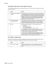
... problem, then check the springs and charge roll link arm assemblies for toner buildup or other parts inside the print cartridge. If this service check. Repair or replace as necessary. If this does not correct the problem, replace the system board. The hot roll especially might cause toner to the bands... on the page. 2-120 Service Manual See if the problem changes or goes away. Check the following voltages at J15-8 on one or both sides of the copy and can be...
... problem, then check the springs and charge roll link arm assemblies for toner buildup or other parts inside the print cartridge. If this service check. Repair or replace as necessary. If this does not correct the problem, replace the system board. The hot roll especially might cause toner to the bands... on the page. 2-120 Service Manual See if the problem changes or goes away. Check the following voltages at J15-8 on one or both sides of the copy and can be...