User's Guide (7.1 MB)
Page 161
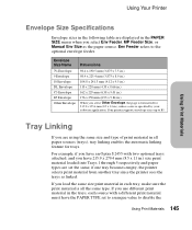
... in the PAPER SIZE menu when you load the same size print material in each source with two optional trays attached, and you have an Optra S 2455 with a different print material must have 215.9 x 279.4 mm (8.5 x 11 in.) size print material loaded into Trays 1 through 5 respectively and paper types are set to... in all the same type. Your printer supports envelope sizes up to the optional envelope feeder. If you select Env Feeder, MP Feeder Size, or Manual Env Size as linked.
... in the PAPER SIZE menu when you load the same size print material in each source with two optional trays attached, and you have an Optra S 2455 with a different print material must have 215.9 x 279.4 mm (8.5 x 11 in.) size print material loaded into Trays 1 through 5 respectively and paper types are set to... in all the same type. Your printer supports envelope sizes up to the optional envelope feeder. If you select Env Feeder, MP Feeder Size, or Manual Env Size as linked.
Service Manual
Page 4
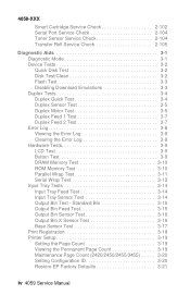
... Sensor Test 3-17 Print Registration 3-18 Printer Setup 3-19 Setting the Page Count 3-19 Viewing the Permanent Page Count 3-19 Maintenance Page Count (2420/2450/2455/3455) . . . . . 3-20 Setting Configuration ID 3-20 Restore EP Factory Defaults 3-21 iv 4059 Service...
... Sensor Test 3-17 Print Registration 3-18 Printer Setup 3-19 Setting the Page Count 3-19 Viewing the Permanent Page Count 3-19 Maintenance Page Count (2420/2450/2455/3455) . . . . . 3-20 Setting Configuration ID 3-20 Restore EP Factory Defaults 3-21 iv 4059 Service...

Service Manual
Page 6
... 5-19 Autoconnect - Level 1 Stepper Motor 5-22 Output Expander Control Board - Level 2 DC Motor . . . . 5-24 Preventive Maintenance 6-1 Safety Inspection Guide 6-1 Lubrication Specifications 6-1 Scheduled Maintenance (2420/2450/2455/3455 6-2 vi 4059 Service Manual Top 5-21 Output Expander Control Board -
... 5-19 Autoconnect - Level 1 Stepper Motor 5-22 Output Expander Control Board - Level 2 DC Motor . . . . 5-24 Preventive Maintenance 6-1 Safety Inspection Guide 6-1 Lubrication Specifications 6-1 Scheduled Maintenance (2420/2450/2455/3455 6-2 vi 4059 Service Manual Top 5-21 Output Expander Control Board -

Service Manual
Page 52
... installed. Print quality - Go to the "Paper Feed Service Check" on page 2-74. Blank Page" on page 2-92. Base Printer Symptom Auxiliary Fan (2420/2450/2455/ 3455) fails to the "Paper Feed Service Check" on page 2-35. Printer sounds 5 beeps. Go to run or is noisy. Go to "Print Quality - All... blank. Paper jams at exit of Redrive Assembly - Go to "Print Quality - Go to the "Operator Panel Service Check" on page 2-101. 2-25 4059 Service Manual
... installed. Print quality - Go to the "Paper Feed Service Check" on page 2-74. Blank Page" on page 2-92. Base Printer Symptom Auxiliary Fan (2420/2450/2455/ 3455) fails to the "Paper Feed Service Check" on page 2-35. Printer sounds 5 beeps. Go to run or is noisy. Go to "Print Quality - All... blank. Paper jams at exit of Redrive Assembly - Go to "Print Quality - Go to the "Operator Panel Service Check" on page 2-101. 2-25 4059 Service Manual

Service Manual
Page 74
...for +24 V dc on J7-1 on the engine board and at J7-1 measures approximately +12 V dc. Note: When the printer is in models 2420, 2450, 2455 and 3455. When the printer is noisy. Check the continuity of the cable. 4059-XXX Fan Service Check Auxiliary Fan Service Check The auxiliary fan... on connector J7 on the engine board. Check the cable connection to the engine board, J1 for excessive noise. Check to Engine Board Cable Action Manually spin the fan and check that it rotates freely. FRU 1 Fan Assembly 2 Engine Board Action Check the fan for proper installation and for correct ...
...for +24 V dc on J7-1 on the engine board and at J7-1 measures approximately +12 V dc. Note: When the printer is in models 2420, 2450, 2455 and 3455. When the printer is noisy. Check the continuity of the cable. 4059-XXX Fan Service Check Auxiliary Fan Service Check The auxiliary fan... on connector J7 on the engine board. Check the cable connection to the engine board, J1 for excessive noise. Check to Engine Board Cable Action Manually spin the fan and check that it rotates freely. FRU 1 Fan Assembly 2 Engine Board Action Check the fan for proper installation and for correct ...
Service Manual
Page 78
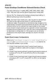
... can be used with a level I fuser board uses +42 V dc which is in configuration 2. If the jumpers are correctly positioned as described in models 3455, 2455, 2450, 2420, 1855, 1650, 1625 and 1620 and the World Trade printer model 2450. A level I fuser board and a level I fuser board and level II engine... identify the level boards installed in your printer. 1. A level I engine board require a envelope conditioner cable and no jumpers on the engine board. 2-51 4059 Service Manual
... can be used with a level I fuser board uses +42 V dc which is in configuration 2. If the jumpers are correctly positioned as described in models 3455, 2455, 2450, 2420, 1855, 1650, 1625 and 1620 and the World Trade printer model 2450. A level I fuser board and a level I fuser board and level II engine... identify the level boards installed in your printer. 1. A level I engine board require a envelope conditioner cable and no jumpers on the engine board. 2-51 4059 Service Manual
Service Manual
Page 104
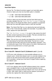
...to make sure the fixed disk and the fixed disk board are servicing a 1650, 1855, 2420, 2450 or 2455 and the network card works in another slot, replace the interconnect board. 2-77 4059 Service Manual Network Card X (X=Network card 1, 2, or 3) A 976 error code indicates an unrecoverable software error in ...the Format Disk Menu operation. 4059-XXX Hard Disk Option Service Tip: The Optra S printers support one hard disk option is installed. • 1.4 GB - 1250/1620/1650/2420/2450 • 2.1 GB - 1255/1625/1855/2455/3455 Check to help restore the disk if the disk contains bad data ...
...to make sure the fixed disk and the fixed disk board are servicing a 1650, 1855, 2420, 2450 or 2455 and the network card works in another slot, replace the interconnect board. 2-77 4059 Service Manual Network Card X (X=Network card 1, 2, or 3) A 976 error code indicates an unrecoverable software error in ...the Format Disk Menu operation. 4059-XXX Hard Disk Option Service Tip: The Optra S printers support one hard disk option is installed. • 1.4 GB - 1250/1620/1650/2420/2450 • 2.1 GB - 1255/1625/1855/2455/3455 Check to help restore the disk if the disk contains bad data ...
Service Manual
Page 132
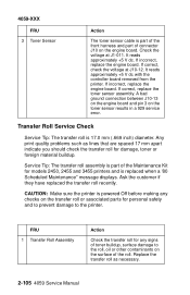
It reads approximately +5 V dc with the controller board removed from the printer. Any print quality problems such as necessary. 2-105 4059 Service Manual CAUTION: Make sure the printer is powered Off before making any checks on the transfer roll or associated parts for any signs of toner buildup, ... the engine board. Replace the transfer roll as lines that are spaced 17 mm apart indicate you should check the transfer roll for models 2450, 2455 and 3455 printers and is 17.0 mm (.669 inch) diameter.
It reads approximately +5 V dc with the controller board removed from the printer. Any print quality problems such as necessary. 2-105 4059 Service Manual CAUTION: Make sure the printer is powered Off before making any checks on the transfer roll or associated parts for any signs of toner buildup, ... the engine board. Replace the transfer roll as lines that are spaced 17 mm apart indicate you should check the transfer roll for models 2450, 2455 and 3455 printers and is 17.0 mm (.669 inch) diameter.

Service Manual
Page 166
... it indicates a factory setting to select the value. Adjust the gap setting by using the Menu < > button to minimum gap. Printer Model 2420/2450/2455 1620/1625/1650/1855 3455 Solenoid Air Gap 4.4 mm (.170 inch) 3.9 mm (.153 inch) 4.8 mm (.153 inch) Gap Adjustment The gap adjustment ...such as they are fed through the printer. Select GAP ADJUST 4. Adjust the fuser solenoid while installed in duplex mode. 4-3 4059 Service Manual The range of the GAP adjustment is noticed. It may take several copies of some printed media thus improving media stacking in reducing the ...
... it indicates a factory setting to select the value. Adjust the gap setting by using the Menu < > button to minimum gap. Printer Model 2420/2450/2455 1620/1625/1650/1855 3455 Solenoid Air Gap 4.4 mm (.170 inch) 3.9 mm (.153 inch) 4.8 mm (.153 inch) Gap Adjustment The gap adjustment ...such as they are fed through the printer. Select GAP ADJUST 4. Adjust the fuser solenoid while installed in duplex mode. 4-3 4059 Service Manual The range of the GAP adjustment is noticed. It may take several copies of some printed media thus improving media stacking in reducing the ...

Service Manual
Page 230
J5 Printhead 1 2 3 4 5 6 7 8 9 10 J6 Output Level Sensor 1 2 3 4 5 J7 Auxiliary Fan 1 (Model 2420/2450/2455/ 3455) 2 J8 Printhead HYSNC 1 2 3 4 J9 Fuser Inductor Sense 1 WT 2450 Only 2 Signal LENA* Ground LAOJ* Ground LASERPWM +5 V dc Ground Video* Ground Ground Ground Ground Opt2 Opt1 +5 V dc CRFANONn Ground Ground HSYNC* Ground +5 V dc FISENSEn Ground 5-5 4059 Service Manual 4059-XXX Connector Pin No.
J5 Printhead 1 2 3 4 5 6 7 8 9 10 J6 Output Level Sensor 1 2 3 4 5 J7 Auxiliary Fan 1 (Model 2420/2450/2455/ 3455) 2 J8 Printhead HYSNC 1 2 3 4 J9 Fuser Inductor Sense 1 WT 2450 Only 2 Signal LENA* Ground LAOJ* Ground LASERPWM +5 V dc Ground Video* Ground Ground Ground Ground Opt2 Opt1 +5 V dc CRFANONn Ground Ground HSYNC* Ground +5 V dc FISENSEn Ground 5-5 4059 Service Manual 4059-XXX Connector Pin No.
Service Manual
Page 240
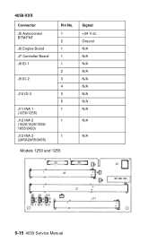
4059-XXX Connector J5 Autoconnect BTM/FNT J6 Engine Board J7 Controller Board J8 ID-1 J9 ID-2 J10 ID-3 J11 INA 1 (1250/1255) J12 INA 2 (1620/1625/1650/ 1855/2420) J13 INA 3 (2450/2455/3455) Pin No. 1 2 1 1 1 2 3 4 5 6 1 1 1 Models 1250 and 1255 Signal +24 V dc Ground N/A N/A N/A N/A N/A N/A N/A N/A N/A N/A N/A 5-15 4059 Service Manual
4059-XXX Connector J5 Autoconnect BTM/FNT J6 Engine Board J7 Controller Board J8 ID-1 J9 ID-2 J10 ID-3 J11 INA 1 (1250/1255) J12 INA 2 (1620/1625/1650/ 1855/2420) J13 INA 3 (2450/2455/3455) Pin No. 1 2 1 1 1 2 3 4 5 6 1 1 1 Models 1250 and 1255 Signal +24 V dc Ground N/A N/A N/A N/A N/A N/A N/A N/A N/A N/A N/A 5-15 4059 Service Manual

Service Manual
Page 252
...The parts are available as a maintenance kit with the following part numbers: 99A0290 - 100V/750W 2450 99A0500 - 115V/750W 2420/2450/2455 99A0503 - 220V/750W 2420/2450/2455 99A0823 - 115V/750W 3455 99A0824 - 220V/750W 3455 After replacing the kit, the maintenance count must be reset to zero to "...Maintenance Page Count (2420/2450/2455/3455)" on page 3-20. 6-2 4059 Service Manual It is necessary to replace the fuser assembly, transfer roller, compensator pick-rolls and charge roll at each 250K page count ...
...The parts are available as a maintenance kit with the following part numbers: 99A0290 - 100V/750W 2450 99A0500 - 115V/750W 2420/2450/2455 99A0503 - 220V/750W 2420/2450/2455 99A0823 - 115V/750W 3455 99A0824 - 220V/750W 3455 After replacing the kit, the maintenance count must be reset to zero to "...Maintenance Page Count (2420/2450/2455/3455)" on page 3-20. 6-2 4059 Service Manual It is necessary to replace the fuser assembly, transfer roller, compensator pick-rolls and charge roll at each 250K page count ...

Service Manual
Page 340
... with T-connector 1 Omni Bus INA Card 1 IR Adapter 1 Hard Disk, w/o Control Board 1250/1620/1650/2420/2450 1 Hard Disk, w/o Control Board 2.1GB 1255/1625/1855/2455/3455 1 Board, Hard Disk Control 1 SIMM, IPDS Board 1250/1620/1650/2420/2450 1 SIMM, IPDS Board 1255/1625/1855...
... with T-connector 1 Omni Bus INA Card 1 IR Adapter 1 Hard Disk, w/o Control Board 1250/1620/1650/2420/2450 1 Hard Disk, w/o Control Board 2.1GB 1255/1625/1855/2455/3455 1 Board, Hard Disk Control 1 SIMM, IPDS Board 1250/1620/1650/2420/2450 1 SIMM, IPDS Board 1255/1625/1855...

Service Manual
Page 346
... 4-31 Fuser Exit Roll Assembly 4-32 Safety Information xvii Fuser Lamp 4-33 Safety Inspection Guide 6-1 Fuser Lower Exit Guide Assembly Scheduled Maintenance (2420/2450/ 4-33 2455/3455) 6-2 Fuser Transfer Plate 4-30 Screw Identification Table 4-7 HVPS 4-34 Serial Wrap Test 3-12 Inner EMC Shield 4-35 Service Checks Inner Paper Deflector Assembly Charge... Input Sensor 2-57 Assembly 4-46 Input Tray(s) Option 2-58 Operator Panel 4-48 Main Drive 2-73 Operator Panel Cable/Cover Open Operator Panel 2-74 I-3 4059 Service Manual
... 4-31 Fuser Exit Roll Assembly 4-32 Safety Information xvii Fuser Lamp 4-33 Safety Inspection Guide 6-1 Fuser Lower Exit Guide Assembly Scheduled Maintenance (2420/2450/ 4-33 2455/3455) 6-2 Fuser Transfer Plate 4-30 Screw Identification Table 4-7 HVPS 4-34 Serial Wrap Test 3-12 Inner EMC Shield 4-35 Service Checks Inner Paper Deflector Assembly Charge... Input Sensor 2-57 Assembly 4-46 Input Tray(s) Option 2-58 Operator Panel 4-48 Main Drive 2-73 Operator Panel Cable/Cover Open Operator Panel 2-74 I-3 4059 Service Manual

