
Card Stock & Label Guide
Page 23
To avoid exposing adhesive to the paper path guides, drive rollers, charge roller, photoconductor drum, transfer roller, and detack fingers, use zone coating. Zone coating means placing the adhesive only where needed. This design requires a stiffer backing material to ...
To avoid exposing adhesive to the paper path guides, drive rollers, charge roller, photoconductor drum, transfer roller, and detack fingers, use zone coating. Zone coating means placing the adhesive only where needed. This design requires a stiffer backing material to ...

Service Manual
Page 22
... Stimulated Emission of Radiation Liquid Crystal Display Light-Emitting Diode Low Voltage Power Supply Masked Read Only Memory Nonvolatile Random Access Memory Original Equipment Manufacturer Photoconductor Power-On Self Test Read Only Memory Single In-Line Memory Module Static Random Access Memory Used Parts Return Volts alternating current Volts direct current...
... Stimulated Emission of Radiation Liquid Crystal Display Light-Emitting Diode Low Voltage Power Supply Masked Read Only Memory Nonvolatile Random Access Memory Original Equipment Manufacturer Photoconductor Power-On Self Test Read Only Memory Single In-Line Memory Module Static Random Access Memory Used Parts Return Volts alternating current Volts direct current...

Service Manual
Page 37
... such as necessary. If any spots or marks, especially ones that appear in the same spot on the printed page, replace the photoconductor unit. FRU Action 1 Photoconduc- Intermittent failure of these are Motor Gears operating correctly and turning the charge brush. 3 Charge Brush...failure of these are found , replace the charge brush bias contact. 4 Photoconduc- ductor unit assembly. If no problems are found, replace the photoconductor unit ground contact. 5 HVPS board Unplug the machine and check the HVPS for a damaged charge brush contact. 2 Main Drive Be sure ...
... such as necessary. If any spots or marks, especially ones that appear in the same spot on the printed page, replace the photoconductor unit. FRU Action 1 Photoconduc- Intermittent failure of these are Motor Gears operating correctly and turning the charge brush. 3 Charge Brush...failure of these are found , replace the charge brush bias contact. 4 Photoconduc- ductor unit assembly. If no problems are found, replace the photoconductor unit ground contact. 5 HVPS board Unplug the machine and check the HVPS for a damaged charge brush contact. 2 Main Drive Be sure ...

Service Manual
Page 47
... the motor. Frame rectly installed and the drive gear is engaging Assembly correctly. 4 Associated Check the fuser gears, print cartridge, transfer Gears roll gear and photoconductor unit gears to CN2-5, 3 - 5 ohms 2 Left Side Remove the toner cartridge and print cartridge. Repair as necessary. 3 Paper Feed Be sure the paper feed frame...
... the motor. Frame rectly installed and the drive gear is engaging Assembly correctly. 4 Associated Check the fuser gears, print cartridge, transfer Gears roll gear and photoconductor unit gears to CN2-5, 3 - 5 ohms 2 Left Side Remove the toner cartridge and print cartridge. Repair as necessary. 3 Paper Feed Be sure the paper feed frame...
Service Manual
Page 56
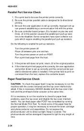
...of time. 2-34 Improper set up resistors. Be sure controller board jumper J3 is installed. Do the following to remove the toner cartridge and photoconductor unit assemblies. Run a print test page from the host, replace the controller board. If the internal print test page prints correctly, the ...the printhead shutter actuator at the same time. Paper Feed Service Check CAUTION: To check the paper feed it covered. Do not expose the photoconductor unit to run the machine with the printer. 4. If the printer still does not print, return J3 to be necessary to direct sunlight...
...of time. 2-34 Improper set up resistors. Be sure controller board jumper J3 is installed. Do the following to remove the toner cartridge and photoconductor unit assemblies. Run a print test page from the host, replace the controller board. If the internal print test page prints correctly, the ...the printhead shutter actuator at the same time. Paper Feed Service Check CAUTION: To check the paper feed it covered. Do not expose the photoconductor unit to run the machine with the printer. 4. If the printer still does not print, return J3 to be necessary to direct sunlight...

Service Manual
Page 60
... correctly and tridge not low on the page and these marks or bars are 126 mm (4.9 inches) or 55 mm (2.2 inches) apart, check the photoconductor unit. 3 Transfer Assembly Replace the transfer assembly if you have a horizontal black bar 57 mm from the top of print quality prob- Be sure the... is correctly tor Unit installed and the cartridge drive is clean, especially around the paper path, print cartridge, and photoconductor unit. • Some types of paper can cause print quality problems. Print quality problems can also be caused by extreme environmental conditions like high ...
... correctly and tridge not low on the page and these marks or bars are 126 mm (4.9 inches) or 55 mm (2.2 inches) apart, check the photoconductor unit. 3 Transfer Assembly Replace the transfer assembly if you have a horizontal black bar 57 mm from the top of print quality prob- Be sure the... is correctly tor Unit installed and the cartridge drive is clean, especially around the paper path, print cartridge, and photoconductor unit. • Some types of paper can cause print quality problems. Print quality problems can also be caused by extreme environmental conditions like high ...

Service Manual
Page 61
... located on the right side frame. 4026-0XX Spot or Marks At Same Spot On Every Print Note: Do not expose the photoconductor to evenly distribute the toner. 2 Printhead Be sure the printhead actuator in the top cover actuates the printhead switch in the printhead...Black Page Note: Incorrect laser exposure or incorrect charging of the photoconductor causes an all black page. Replace as necessary. FRU Action 1 Photoconduc- Diagnostic Information 2-39 Remove the photoconductor unit assembly and tor Unit check the photoconductor for voids, spots, or Assembly damage. 2 Fuser Paper If ...
... located on the right side frame. 4026-0XX Spot or Marks At Same Spot On Every Print Note: Do not expose the photoconductor to evenly distribute the toner. 2 Printhead Be sure the printhead actuator in the top cover actuates the printhead switch in the printhead...Black Page Note: Incorrect laser exposure or incorrect charging of the photoconductor causes an all black page. Replace as necessary. FRU Action 1 Photoconduc- Diagnostic Information 2-39 Remove the photoconductor unit assembly and tor Unit check the photoconductor for voids, spots, or Assembly damage. 2 Fuser Paper If ...

Service Manual
Page 62
... the order shown: Engine Board, HVPS Printhead Assembly Engine board HVPS White or Black Lines or Bands Note: Poor image development, incorrect charging of the photoconductor, incorrect laser exposure, poor image transfer, or poor fusing causes white/black bands or lines. FRU Action 1 Toner Car- Check the...
... the order shown: Engine Board, HVPS Printhead Assembly Engine board HVPS White or Black Lines or Bands Note: Poor image development, incorrect charging of the photoconductor, incorrect laser exposure, poor image transfer, or poor fusing causes white/black bands or lines. FRU Action 1 Toner Car- Check the...

Service Manual
Page 64
... Light Print Action Check the transfer assembly for damage and pitted or contaminated contacts. If no problem is found , replace the photoconductor unit. 2-42 conductor unit does not correct the problem, replace the following FRUs one at a time in the area of life... or foreign objects attached to or in the order shown: Transfer Assembly HVPS FRU Action 1 Photoconduc- Be sure the toner cartridge and photoconductor tridge, Photo- Unit conductor unit. This is correctly tor Unit installed. unit are installed correctly. If installed correctly, conductor try a...
... Light Print Action Check the transfer assembly for damage and pitted or contaminated contacts. If no problem is found , replace the photoconductor unit. 2-42 conductor unit does not correct the problem, replace the following FRUs one at a time in the area of life... or foreign objects attached to or in the order shown: Transfer Assembly HVPS FRU Action 1 Photoconduc- Be sure the toner cartridge and photoconductor tridge, Photo- Unit conductor unit. This is correctly tor Unit installed. unit are installed correctly. If installed correctly, conductor try a...

Service Manual
Page 66
...correctly installed and the transfer assembly is correctly installed and the left and right transfer bracket springs bias the transfer assembly toward the photoconductor unit. Replace the transfer assembly if you have a horizontal black bar 57 mm from the top of damage or poor contact. ... for damage or broken teeth. FRU 1 Transfer Assembly Action Be sure the transfer assembly is free to move and biased toward the photoconductor unit. Be sure the left and right transfer bracket springs are properly positioned and fastened. Check the transfer roll for damage. FRU ...
...correctly installed and the transfer assembly is correctly installed and the left and right transfer bracket springs bias the transfer assembly toward the photoconductor unit. Replace the transfer assembly if you have a horizontal black bar 57 mm from the top of damage or poor contact. ... for damage or broken teeth. FRU 1 Transfer Assembly Action Be sure the transfer assembly is free to move and biased toward the photoconductor unit. Be sure the left and right transfer bracket springs are properly positioned and fastened. Check the transfer roll for damage. FRU ...

Service Manual
Page 83
Use caution when the photoconductor unit is out of the covers removed. Screw Identification Table Repair Information 4-3 4026-0XX Removal Procedures CAUTION: Be sure to light for more than 15 - 20 minutes. Do not expose it to unplug the power cord whenever you are working on the printer with one of the machine.
Use caution when the photoconductor unit is out of the covers removed. Screw Identification Table Repair Information 4-3 4026-0XX Removal Procedures CAUTION: Be sure to light for more than 15 - 20 minutes. Do not expose it to unplug the power cord whenever you are working on the printer with one of the machine.

Service Manual
Page 113
4026-0XX AsmIndex 2-1 2-1 2-2 2-2 2-3 2-4 2-5 2-6 2-7 2-8 2-9 2-9A Part Number 69G9962 11A7381 69G9691 11A7382 69G8345 69G8346 69G8347 11A7420 Units 1 1 1 1 2 1 3 2 1 1 1 1 Description Motor, Main Drive 06A/06B/06D/06J/070 Motor, Main Drive 06C/06F/071 Left Side Plate Motor Bracket 06A/06B/06D/ 06J/070 Left Side Plate Motor Bracket 06C/06F/071 Screw, Type 1308 PP 69G9974 Screw, Type 3501 PP 69G9974 Screw, Type 3704 PP 69G9974 Screw, Type 3504 PP 69G9974 Left Side Plate Guide, photoconductor unit Guide, Toner Cartridge/Photoconductor Unit Bracket, Printhead Mounting Parts Catalog 6-7
4026-0XX AsmIndex 2-1 2-1 2-2 2-2 2-3 2-4 2-5 2-6 2-7 2-8 2-9 2-9A Part Number 69G9962 11A7381 69G9691 11A7382 69G8345 69G8346 69G8347 11A7420 Units 1 1 1 1 2 1 3 2 1 1 1 1 Description Motor, Main Drive 06A/06B/06D/06J/070 Motor, Main Drive 06C/06F/071 Left Side Plate Motor Bracket 06A/06B/06D/ 06J/070 Left Side Plate Motor Bracket 06C/06F/071 Screw, Type 1308 PP 69G9974 Screw, Type 3501 PP 69G9974 Screw, Type 3704 PP 69G9974 Screw, Type 3504 PP 69G9974 Left Side Plate Guide, photoconductor unit Guide, Toner Cartridge/Photoconductor Unit Bracket, Printhead Mounting Parts Catalog 6-7

Service Manual
Page 115
.../72T PP 69G9989 Gear, 22/45T PP 69G9989 Gear, 50T PP 69G9989 Terminal, Rt Side Ground LVPS to Bd Cage Terminal, Rt Side Photoconductor Unit Ground Terminal, Rt SIde, Photoconductor Unit Charge Bias Terminal, Rt Side Toner Cartridge Spring, Rt Side Frame, Cartridge Latching PP 69G9987 Terminal, Rt Side Ground HVPS to...
.../72T PP 69G9989 Gear, 22/45T PP 69G9989 Gear, 50T PP 69G9989 Terminal, Rt Side Ground LVPS to Bd Cage Terminal, Rt Side Photoconductor Unit Ground Terminal, Rt SIde, Photoconductor Unit Charge Bias Terminal, Rt Side Toner Cartridge Spring, Rt Side Frame, Cartridge Latching PP 69G9987 Terminal, Rt Side Ground HVPS to...


