User's Guide
Page 22
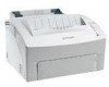
...in the name of the printer dialog box show the Optra E312 printer icon. 15 In the PostScript Printer Description (PPD) File box, click Auto Setup. Connecting the printer to your Desktop. 20 Click the new desktop printer icon. Note: Both areas of the printer or accept the default name....Save. 19 Quit the Desktop Printer Utility application. Wait for you to process. A dark line appears around the printer in the PostScript Printer Description (PPD) File box What to indicate it is selected as the default printer. Notice the new printer icon. 16 Click Create. Troubleshooting Tips ...
...in the name of the printer dialog box show the Optra E312 printer icon. 15 In the PostScript Printer Description (PPD) File box, click Auto Setup. Connecting the printer to your Desktop. 20 Click the new desktop printer icon. Note: Both areas of the printer or accept the default name....Save. 19 Quit the Desktop Printer Utility application. Wait for you to process. A dark line appears around the printer in the PostScript Printer Description (PPD) File box What to indicate it is selected as the default printer. Notice the new printer icon. 16 Click Create. Troubleshooting Tips ...
User's Guide
Page 29
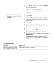
7 Grasp the corner of the shield and gently pull it out, then down. 8 Pull the shield away from the printer. 16 Chapter 1: The basics
7 Grasp the corner of the shield and gently pull it out, then down. 8 Pull the shield away from the printer. 16 Chapter 1: The basics
User's Guide
Page 39
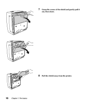
If the paper has a preferred print side, load it with the print side facing you. Media Paper Size A4, A5, B5, letter, legal, executive Weight 16 - 24 lb (60-90 g/m2) Capacity Automatic Paper Feeder: 150 sheets Manual Sheet Feeder: 1 sheet Transparencies Envelopes Labels Index Cards Index Bristol / Tag Card Stock ...) Minimum: 3 x 5 in. (76.2 x 127.0 mm) Minimum: 3 x 5 in. (76.2 x 127.0 mm) Maximum: 8.5 x 14 in. (216 mm x 356 mm) 16 - 43 lb (60-163 g/m2) 16 - 43 lb (60-163 g/m2) 16 - 43 lb (60-163 g/m2) 16 - 43 lb (60-163 g/m2) 67 - 90 lb Index Bristol (120 - 163 g/m2) 50 - 100 lb tag (75...
If the paper has a preferred print side, load it with the print side facing you. Media Paper Size A4, A5, B5, letter, legal, executive Weight 16 - 24 lb (60-90 g/m2) Capacity Automatic Paper Feeder: 150 sheets Manual Sheet Feeder: 1 sheet Transparencies Envelopes Labels Index Cards Index Bristol / Tag Card Stock ...) Minimum: 3 x 5 in. (76.2 x 127.0 mm) Minimum: 3 x 5 in. (76.2 x 127.0 mm) Maximum: 8.5 x 14 in. (216 mm x 356 mm) 16 - 43 lb (60-163 g/m2) 16 - 43 lb (60-163 g/m2) 16 - 43 lb (60-163 g/m2) 16 - 43 lb (60-163 g/m2) 67 - 90 lb Index Bristol (120 - 163 g/m2) 50 - 100 lb tag (75...
User's Guide
Page 79
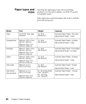
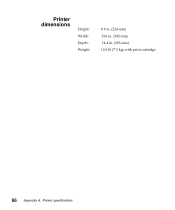
Printer dimensions Height: Width: Depth: Weight: 8.8 in. (224 mm) 13.6 in. (345 mm) 14.4 in. (365 mm) 16.5 lb (7.5 kg) with print cartridge 66 Appendix A: Printer specifications
Printer dimensions Height: Width: Depth: Weight: 8.8 in. (224 mm) 13.6 in. (345 mm) 14.4 in. (365 mm) 16.5 lb (7.5 kg) with print cartridge 66 Appendix A: Printer specifications
Service Manual
Page 4
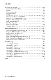
... Assembly 4-18 Printhead Assembly 4-20 Transfer Roll 4-21 Connector Locations 5-1 Controller Board (model E310/E312 5-1 Engine/LVPS Board (model E310 5-4 Engine Board (model E312 5-9 LVPS (model E312 5-14 High Voltage Power Supply (model E310 5-16 High Voltage Power Supply (model E312 5-18 Interconnect Board (model E310 5-21 Parts Catalog 6-1 Assembly 1: Covers 6-2 Assembly 2: Frame 6-6 Assembly 3: Fuser...
... Assembly 4-18 Printhead Assembly 4-20 Transfer Roll 4-21 Connector Locations 5-1 Controller Board (model E310/E312 5-1 Engine/LVPS Board (model E310 5-4 Engine Board (model E312 5-9 LVPS (model E312 5-14 High Voltage Power Supply (model E310 5-16 High Voltage Power Supply (model E312 5-18 Interconnect Board (model E310 5-21 Parts Catalog 6-1 Assembly 1: Covers 6-2 Assembly 2: Frame 6-6 Assembly 3: Fuser...
Service Manual
Page 38
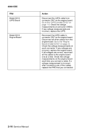
...are incorrect, replace the LVPS. If any voltages are incorrect, replace the engine board. Disconnect all the cables to the "Engine Board (model E312)" on the engine board each connector. Go to the engine board one of the cables, replace the FRU that you connect a cable. Check... Check the voltage measurements at each time you connected. 2-16 Service Manual Reconnect the LVPS cable to the "LVPS (model E312)" on the engine board. Go to connector CN7 on page -14. 4044-XXX FRU Model E312 LVPS Board Model E312 Engine Board Action Disconnect the LVPS cable from the engine board...
...are incorrect, replace the LVPS. If any voltages are incorrect, replace the engine board. Disconnect all the cables to the "Engine Board (model E312)" on the engine board each connector. Go to the engine board one of the cables, replace the FRU that you connect a cable. Check... Check the voltage measurements at each time you connected. 2-16 Service Manual Reconnect the LVPS cable to the "LVPS (model E312)" on the engine board. Go to connector CN7 on page -14. 4044-XXX FRU Model E312 LVPS Board Model E312 Engine Board Action Disconnect the LVPS cable from the engine board...

Service Manual
Page 50
...than required for continuity. If the problem still exists, replace the engine/LVPS board on the model E310 or the engine board on page 5-16 in the connector locations chapter and check the voltage measurements. If the cable does not measure continuity, replace the cable. 4044-XXX Paper "... Board (Model E312) Remove the toner cartridge and gently shake the assembly to a worn transfer roller. Disconnect the printhead cable from the HVPS and measure the signals on connectors CN3 and CN4. If the voltages are not correct, replace the HVPS. A worn transfer roller causes the printer to the "...
...than required for continuity. If the problem still exists, replace the engine/LVPS board on the model E310 or the engine board on page 5-16 in the connector locations chapter and check the voltage measurements. If the cable does not measure continuity, replace the cable. 4044-XXX Paper "... Board (Model E312) Remove the toner cartridge and gently shake the assembly to a worn transfer roller. Disconnect the printhead cable from the HVPS and measure the signals on connectors CN3 and CN4. If the voltages are not correct, replace the HVPS. A worn transfer roller causes the printer to the "...

Service Manual
Page 74
4044-XXX 3-16 Service Manual
4044-XXX 3-16 Service Manual
Service Manual
Page 90
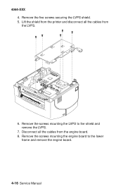
Remove the screws mounting the LVPS to the lower frame and remove the engine board. 4-16 Service Manual 4044-XXX 4. Remove the screws mounting the engine board to the shield and remove the LVPS. 7. Disconnect all the cables from the engine board. 8. Lift the shield from the printer and disconnect all the cables from the LVPS. 6. Remove the five screws securing the LVPS shield. 5.
Remove the screws mounting the LVPS to the lower frame and remove the engine board. 4-16 Service Manual 4044-XXX 4. Remove the screws mounting the engine board to the shield and remove the LVPS. 7. Disconnect all the cables from the engine board. 8. Lift the shield from the printer and disconnect all the cables from the LVPS. 6. Remove the five screws securing the LVPS shield. 5.
Service Manual
Page 98
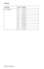
Signal 15 +5 V dc 16 +5 V dc 17 +5 V dc 18 Ground 19 Ground 20 Ground 21 Ground 22 Ground 23 +5 V dc 24 +5 V dc 5-2 Service Manual 4044-XXX Connector J7 (continued) Pin No.
Signal 15 +5 V dc 16 +5 V dc 17 +5 V dc 18 Ground 19 Ground 20 Ground 21 Ground 22 Ground 23 +5 V dc 24 +5 V dc 5-2 Service Manual 4044-XXX Connector J7 (continued) Pin No.
Service Manual
Page 101
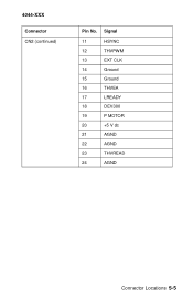
Signal 11 HSYNC 12 THVPWM 13 EXT CLK 14 Ground 15 Ground 16 THVEA 17 LREADY 18 DEV300 19 P MOTOR 20 +5 V dc 21 AGND 22 AGND 23 THVREAD 24 AGND Connector Locations 5-5 4044-XXX Connector CN2 (continued) Pin No.
Signal 11 HSYNC 12 THVPWM 13 EXT CLK 14 Ground 15 Ground 16 THVEA 17 LREADY 18 DEV300 19 P MOTOR 20 +5 V dc 21 AGND 22 AGND 23 THVREAD 24 AGND Connector Locations 5-5 4044-XXX Connector CN2 (continued) Pin No.
Service Manual
Page 102
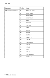
4044-XXX Connector CN4 Interconnect Board Pin No. Signal 1 DEV FUSE FAN J 2 MOTOR EA J 3 MOTOR PB J 4 MOTOR PA J 5 AGND 6 NEW DEV J 7 PFEED J 8 AGND 9 Ground 10 Ground 11 CLUTCH J 12 PEMPTY J 13 +24 V dc 14 PNARROW J 15 +5 V dc 16 +24 V dc 17 PTL J 18 +5 V dc 19 PMOTOR EXT J 20 EXT CLK J 5-6 Service Manual
4044-XXX Connector CN4 Interconnect Board Pin No. Signal 1 DEV FUSE FAN J 2 MOTOR EA J 3 MOTOR PB J 4 MOTOR PA J 5 AGND 6 NEW DEV J 7 PFEED J 8 AGND 9 Ground 10 Ground 11 CLUTCH J 12 PEMPTY J 13 +24 V dc 14 PNARROW J 15 +5 V dc 16 +24 V dc 17 PTL J 18 +5 V dc 19 PMOTOR EXT J 20 EXT CLK J 5-6 Service Manual
Service Manual
Page 103
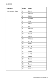
4044-XXX Connector CN5 Controller Board Pin No. Signal 1 EBUSY 2 Not Used 3 EMSG 4 EXITPAP 5 CCLK 6 PRINT 7 VDI 8 Not Used 9 PSYNC 10 READY 11 HSYNC 12 Not Used 13 +5 V dc 14 CMSG 15 +5 V dc 16 +5 V dc 17 Ground 18 +5 V dc 19 Ground 20 Ground 21 Ground 22 Ground 23 VDO 24 Not Used Connector Locations 5-7
4044-XXX Connector CN5 Controller Board Pin No. Signal 1 EBUSY 2 Not Used 3 EMSG 4 EXITPAP 5 CCLK 6 PRINT 7 VDI 8 Not Used 9 PSYNC 10 READY 11 HSYNC 12 Not Used 13 +5 V dc 14 CMSG 15 +5 V dc 16 +5 V dc 17 Ground 18 +5 V dc 19 Ground 20 Ground 21 Ground 22 Ground 23 VDO 24 Not Used Connector Locations 5-7
Service Manual
Page 105
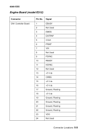
Signal 1 EBUSY 2 Not Used 3 EMSG 4 EXITPAP 5 CCLK 6 PRINT 7 VDI 8 Not Used 9 PSYNC 10 READY 11 HSYNC 12 Not Used 13 +5 V dc 14 CMSG 15 +5 V dc 16 +5 V dc 17 Ground, Floating 18 +5 V dc 19 Ground, Floating 20 Ground, Floating 21 Ground, Floating 22 Ground, Floating 23 VDO 24 Not Used Connector Locations 5-9 4044-XXX Engine Board (model E312) Connector CN1 Controller Board Pin No.
Signal 1 EBUSY 2 Not Used 3 EMSG 4 EXITPAP 5 CCLK 6 PRINT 7 VDI 8 Not Used 9 PSYNC 10 READY 11 HSYNC 12 Not Used 13 +5 V dc 14 CMSG 15 +5 V dc 16 +5 V dc 17 Ground, Floating 18 +5 V dc 19 Ground, Floating 20 Ground, Floating 21 Ground, Floating 22 Ground, Floating 23 VDO 24 Not Used Connector Locations 5-9 4044-XXX Engine Board (model E312) Connector CN1 Controller Board Pin No.
Service Manual
Page 108
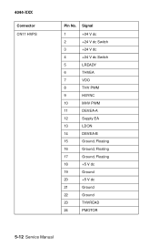
4044-XXX Connector CN11 HVPS Pin No. Signal 1 +24 V dc 2 +24 V dc Switch 3 +24 V dc 4 +24 V dc Switch 5 LREADY 6 THVEA 7 VDO 8 THV PWM 9 HSYNC 10 MHV PWM 11 DEVEA-A 12 Supply EA 13 LDON 14 DEVEA-B 15 Ground, Floating 16 Ground, Floating 17 Ground, Floating 18 +5 V dc 19 Ground 20 +5 V dc 21 Ground 22 Ground 23 THVREAD 24 PMOTOR 5-12 Service Manual
4044-XXX Connector CN11 HVPS Pin No. Signal 1 +24 V dc 2 +24 V dc Switch 3 +24 V dc 4 +24 V dc Switch 5 LREADY 6 THVEA 7 VDO 8 THV PWM 9 HSYNC 10 MHV PWM 11 DEVEA-A 12 Supply EA 13 LDON 14 DEVEA-B 15 Ground, Floating 16 Ground, Floating 17 Ground, Floating 18 +5 V dc 19 Ground 20 +5 V dc 21 Ground 22 Ground 23 THVREAD 24 PMOTOR 5-12 Service Manual
Service Manual
Page 112
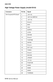
4044-XXX High Voltage Power Supply (model E310) Connector CN1 Engine/LVPS Board Pin No. Signal 1 +24 V dc 2 +24 V dc SWITCH 3 +24 V dc 4 Ground 5 MHV 6 VDO 7 SUPPLY 8 LDON 9 DEV350 10 Ground 11 THVPWM 12 HSYNC 13 Ground 14 EXT CLK 15 THVEA 16 Ground 17 DEV300 18 LREADY 19 +5 V dc 20 P MOTOR 21 AGND 22 AGND 23 AGND 24 THVREAD 5-16 Service Manual
4044-XXX High Voltage Power Supply (model E310) Connector CN1 Engine/LVPS Board Pin No. Signal 1 +24 V dc 2 +24 V dc SWITCH 3 +24 V dc 4 Ground 5 MHV 6 VDO 7 SUPPLY 8 LDON 9 DEV350 10 Ground 11 THVPWM 12 HSYNC 13 Ground 14 EXT CLK 15 THVEA 16 Ground 17 DEV300 18 LREADY 19 +5 V dc 20 P MOTOR 21 AGND 22 AGND 23 AGND 24 THVREAD 5-16 Service Manual
Service Manual
Page 114
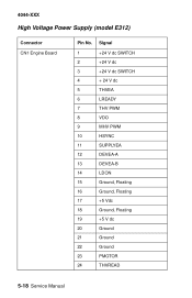
Signal 1 +24 V dc SWITCH 2 +24 V dc 3 +24 V dc SWITCH 4 + 24 V dc 5 THVEA 6 LREADY 7 THV PWM 8 VDO 9 MHV PWM 10 HSYNC 11 SUPPLYEA 12 DEVEA-A 13 DEVEA-B 14 LDON 15 Ground, Floating 16 Ground, Floating 17 +5 Vdc 18 Ground, Floating 19 +5 V dc 20 Ground 21 Ground 22 Ground 23 PMOTOR 24 THVREAD 5-18 Service Manual 4044-XXX High Voltage Power Supply (model E312) Connector CN1 Engine Board Pin No.
Signal 1 +24 V dc SWITCH 2 +24 V dc 3 +24 V dc SWITCH 4 + 24 V dc 5 THVEA 6 LREADY 7 THV PWM 8 VDO 9 MHV PWM 10 HSYNC 11 SUPPLYEA 12 DEVEA-A 13 DEVEA-B 14 LDON 15 Ground, Floating 16 Ground, Floating 17 +5 Vdc 18 Ground, Floating 19 +5 V dc 20 Ground 21 Ground 22 Ground 23 PMOTOR 24 THVREAD 5-18 Service Manual 4044-XXX High Voltage Power Supply (model E312) Connector CN1 Engine Board Pin No.
Service Manual
Page 118
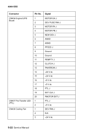
4044-XXX Connector CN406 Engine/LVPS Board CN407 Pre-Transfer LED (PTL) CN408 Cooling Fan Pin No. 1 2 3 4 5 6 7 8 9 10 11 12 13 14 15 16 17 18 19 20 1 2 1 2 3 Signal MOTOR EA J DEV FUSE FAN J MOTOR PA J MOTOR PB J NEW DEV J AGND AGND PFEED J Ground Ground PEMPTY J CLUTCH J PNARROW J +24 V dc +24 V dc +5 V dc +5 V dc PTL J EXT CLK J PMOTOR EXT J PTL J +5 V dc DEV FAN J N/A +24 V dc 5-22 Service Manual
4044-XXX Connector CN406 Engine/LVPS Board CN407 Pre-Transfer LED (PTL) CN408 Cooling Fan Pin No. 1 2 3 4 5 6 7 8 9 10 11 12 13 14 15 16 17 18 19 20 1 2 1 2 3 Signal MOTOR EA J DEV FUSE FAN J MOTOR PA J MOTOR PB J NEW DEV J AGND AGND PFEED J Ground Ground PEMPTY J CLUTCH J PNARROW J +24 V dc +24 V dc +5 V dc +5 V dc PTL J EXT CLK J PMOTOR EXT J PTL J +5 V dc DEV FAN J N/A +24 V dc 5-22 Service Manual
Service Manual
Page 129
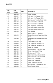
4044-XXX AsmIndex 2-15 2-16 2-16 2-17 2-18 2-18 2-19 2-20 2-20 2-21 2-22 2-23 2-23 2-24 2-25 2-25 2-26 2-27 2-28 2-29 2-30 2-30 2-31 2-31 2-32 2-33 2-34 Part ..., Rubber Screw, Type 3 PP 12G0101 Sensor Asm, Input Paper Feed/Size E310 Sensor Asm, Input Paper Feed/Size E312 Cable Asm, Fuser Lamp Flag, Paper Exit Sensor E310 Flag, Paper Exit Sensor E312 Guide, HV Contact Contact Asm, HV-Transfer Roller Cover, Fuser Lamp Wiring Contact Asm, HV-Main Cable Asm, Power...
4044-XXX AsmIndex 2-15 2-16 2-16 2-17 2-18 2-18 2-19 2-20 2-20 2-21 2-22 2-23 2-23 2-24 2-25 2-25 2-26 2-27 2-28 2-29 2-30 2-30 2-31 2-31 2-32 2-33 2-34 Part ..., Rubber Screw, Type 3 PP 12G0101 Sensor Asm, Input Paper Feed/Size E310 Sensor Asm, Input Paper Feed/Size E312 Cable Asm, Fuser Lamp Flag, Paper Exit Sensor E310 Flag, Paper Exit Sensor E312 Guide, HV Contact Contact Asm, HV-Transfer Roller Cover, Fuser Lamp Wiring Contact Asm, HV-Main Cable Asm, Power...
Service Manual
Page 133
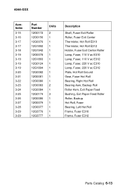
4044-XXX AsmIndex 3-15 3-16 3-17 3-17 3-18 3-19 3-19 3-19 3-19 3-20 3-21 3-22 3-23 3-24 3-25 3-26 3-27 3-28 3-29 3-29 Part Number 12G0172 12G0156 12G0076 12G1892 12G1942 ... Exit Roller Roller, Fuser Exit Center Thermistor, Hot Roll E310 Thermistor, Hot Roll E312 Holder, Fuser Exit Center Roller Lamp, Fuser, 110 V ac E310 Lamp, Fuser, 110 V ac E312 Lamp, Fuser, 220 V ac E310 Lamp, Fuser, 220 V ac E312 Plate, Hot Roll Ground Gear, Fuser Hot Roll Bearing, Right Hot Roll Bearing Asm...
4044-XXX AsmIndex 3-15 3-16 3-17 3-17 3-18 3-19 3-19 3-19 3-19 3-20 3-21 3-22 3-23 3-24 3-25 3-26 3-27 3-28 3-29 3-29 Part Number 12G0172 12G0156 12G0076 12G1892 12G1942 ... Exit Roller Roller, Fuser Exit Center Thermistor, Hot Roll E310 Thermistor, Hot Roll E312 Holder, Fuser Exit Center Roller Lamp, Fuser, 110 V ac E310 Lamp, Fuser, 110 V ac E312 Lamp, Fuser, 220 V ac E310 Lamp, Fuser, 220 V ac E312 Plate, Hot Roll Ground Gear, Fuser Hot Roll Bearing, Right Hot Roll Bearing Asm...
