
Technical Reference
Page 50
... 40038 Fuser Exhausted Intervention Required - 40038 Fuser Life Warning Intervention Required - 40038 Fuser Maintenance Intervention Required - 40038 ITU Maintenance Return string 80 Scheduled Maintenance 81 Scheduled Maintenance 80 Belt Exhausted 80 Belt Life Warning 80 Fuser/Belt Exhausted 80... Fuser/Belt Life Warning 80 Fuser Exhausted 80 Fuser Life Warning 80 Fuser Maintenance 83 ITU Maintenance Printer model C540n, C543dn, C544n/dn/dw/dtn X546dtn MFP X X X X X X X X X X X X X X X X X X X X PJL messages for...
... 40038 Fuser Exhausted Intervention Required - 40038 Fuser Life Warning Intervention Required - 40038 Fuser Maintenance Intervention Required - 40038 ITU Maintenance Return string 80 Scheduled Maintenance 81 Scheduled Maintenance 80 Belt Exhausted 80 Belt Life Warning 80 Fuser/Belt Exhausted 80... Fuser/Belt Life Warning 80 Fuser Exhausted 80 Fuser Life Warning 80 Fuser Maintenance 83 ITU Maintenance Printer model C540n, C543dn, C544n/dn/dw/dtn X546dtn MFP X X X X X X X X X X X X X X X X X X X X PJL messages for...
Service Manual
Page 5
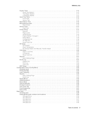
... 3-17 Flash Test 3-17 Printer Setup 3-17 Defaults 3-17 Page counts 3-17 Serial Number 3-18 Engine Setting 1 through 4 3-18 Model Name 3-18 Configuration ID 3-18 ITU Barcode 3-19 Reset Fuser Cnt 3-19 EP Setup 3-19 EP Defaults 3-19 Fuser Temperature 3-19 DC Charge Adjust, Dev Bias Adj, Transfer Adjust 3-20 TPS...
... 3-17 Flash Test 3-17 Printer Setup 3-17 Defaults 3-17 Page counts 3-17 Serial Number 3-18 Engine Setting 1 through 4 3-18 Model Name 3-18 Configuration ID 3-18 ITU Barcode 3-19 Reset Fuser Cnt 3-19 EP Setup 3-19 EP Defaults 3-19 Fuser Temperature 3-19 DC Charge Adjust, Dev Bias Adj, Transfer Adjust 3-20 TPS...
Service Manual
Page 6
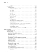
... assembly removal 4-26 Fuser drive motor assembly removal 4-29 Fuser exit sensor removal 4-30 High-voltage power supply (HVPS) assembly removal 4-31 Image transfer unit (ITU) removal 4-33 Imaging unit (IU) removal 4-35 Low-voltage power supply (LVPS) assembly removal 4-37 Lower frame removal, right and left 4-39 Left lower frame...
... assembly removal 4-26 Fuser drive motor assembly removal 4-29 Fuser exit sensor removal 4-30 High-voltage power supply (HVPS) assembly removal 4-31 Image transfer unit (ITU) removal 4-33 Imaging unit (IU) removal 4-35 Low-voltage power supply (LVPS) assembly removal 4-37 Lower frame removal, right and left 4-39 Left lower frame...
Service Manual
Page 20
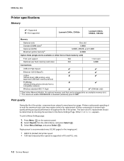
b The maximum usable DDRSDRAM is supported in PS and PCL only 1-2 Service Manual The fuser and ITU replacement should be plugged into an available memory slot. Select Reports from a compatible camera) Wireless standard 802.11 b/g/n ✘ &#... standard (soldered) plus 512MB. Press Menu ( ) on usage. 5025-2xx, 4xx Printer specifications Memory ✔-Supported ✘-Not supported Lexmark C540n, C543dn Lexmark C544n, C544dn, C544dw Memory Optional slots Standard DIMM sizesa Optional (DDR2) Maximum printer memoryb One slot 128MB 128MB, 256MB, and 512MB 640MB...
b The maximum usable DDRSDRAM is supported in PS and PCL only 1-2 Service Manual The fuser and ITU replacement should be plugged into an available memory slot. Select Reports from a compatible camera) Wireless standard 802.11 b/g/n ✘ &#... standard (soldered) plus 512MB. Press Menu ( ) on usage. 5025-2xx, 4xx Printer specifications Memory ✔-Supported ✘-Not supported Lexmark C540n, C543dn Lexmark C544n, C544dn, C544dw Memory Optional slots Standard DIMM sizesa Optional (DDR2) Maximum printer memoryb One slot 128MB 128MB, 256MB, and 512MB 640MB...
Service Manual
Page 33
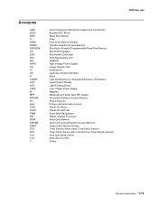
Acronyms ACM BLDC BOR C DIMM DRAM EEPROM EP ESD FRU GB HVPS ITU IU JIS K LASER LCD LED LVPS M MPF NVRAM PC pixel POR POST PWM RIP ROM SDRAM SIMM TDS TPS V ac V dc Y Autocompensator Mechanism (paper pick ...
Acronyms ACM BLDC BOR C DIMM DRAM EEPROM EP ESD FRU GB HVPS ITU IU JIS K LASER LCD LED LVPS M MPF NVRAM PC pixel POR POST PWM RIP ROM SDRAM SIMM TDS TPS V ac V dc Y Autocompensator Mechanism (paper pick ...
Service Manual
Page 37
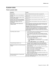
...39. Tray linking does not work . Go to "Operator panel display blank, five beeps" on page 2-37. Therefore the toner goes into the ITU cleaner which cannot process massive amounts of the paper guides. • The multipurpose feeder does not automatically sense the paper size. Select Menu Settings, ...; Make sure the paper is blank. Operator panel-display is loaded correctly in the tray. Unexpected page breaks occur. You must set to the ITU belt but not transferred. Change the setting to "Dead printer service check" on page 2-28. Pages print blank after you clear the jam....
...39. Tray linking does not work . Go to "Operator panel display blank, five beeps" on page 2-37. Therefore the toner goes into the ITU cleaner which cannot process massive amounts of the paper guides. • The multipurpose feeder does not automatically sense the paper size. Select Menu Settings, ...; Make sure the paper is blank. Operator panel-display is loaded correctly in the tray. Unexpected page breaks occur. You must set to the ITU belt but not transferred. Change the setting to "Dead printer service check" on page 2-28. Pages print blank after you clear the jam....

Service Manual
Page 50
...motor Go to "Main drive gear assembly (EP to reach valid FG speed. drive) service check" on page 2-35. 150.02 Service Black/ITU cartridge Motor Timeout waiting for motor. Go to "Autocompensator mechanism timeout. Go to "Main drive gear assembly (EP drive) service check" on ...35. 152.01 Service Failed to achieve lock for second thermistor Go to "Fuser service check" on page 2-35. 150.01 Service Black/ITU cartridge Motor Failed to achieve lock for MP_NUM_INITIAL_SAP_HALLS. Go to "Autocompensator mechanism service check" on page 2-27. 141.01 Service Staging Motor ...
...motor Go to "Main drive gear assembly (EP to reach valid FG speed. drive) service check" on page 2-35. 150.02 Service Black/ITU cartridge Motor Timeout waiting for motor. Go to "Autocompensator mechanism timeout. Go to "Main drive gear assembly (EP drive) service check" on ...35. 152.01 Service Failed to achieve lock for second thermistor Go to "Fuser service check" on page 2-35. 150.01 Service Black/ITU cartridge Motor Failed to achieve lock for MP_NUM_INITIAL_SAP_HALLS. Go to "Autocompensator mechanism service check" on page 2-27. 141.01 Service Staging Motor ...
Service Manual
Page 77
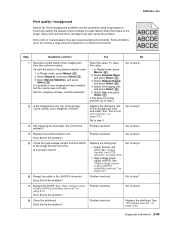
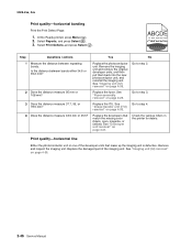
... 7. 7 Replace the HVPS. Problem resolved. Go to step 3. Go to step 4. 4 Replace the photoconductor unit. Using non-Lexmark toner cartridges may also cause background problems. Some problems occur by using rough paper or incorrectly setting the operator panel settings to rough texture...) assembly removal" on page 4-21. Has the imaging unit been recently replaced? 1. Does this fix the problem? See "Image transfer unit (ITU) removal" on page 4-33. • High-voltage power supply (HVPS). Select Yes, and press Select ( ). Print quality-background Service tip...
... 7. 7 Replace the HVPS. Problem resolved. Go to step 3. Go to step 4. 4 Replace the photoconductor unit. Using non-Lexmark toner cartridges may also cause background problems. Some problems occur by using rough paper or incorrectly setting the operator panel settings to rough texture...) assembly removal" on page 4-21. Has the imaging unit been recently replaced? 1. Does this fix the problem? See "Image transfer unit (ITU) removal" on page 4-33. • High-voltage power supply (HVPS). Select Yes, and press Select ( ). Print quality-background Service tip...
Service Manual
Page 79
See "Rear shield removal" on page 4-49. Are all the spring-loaded pins in the HVPS free to move in the image transfer unit (ITU). Enter the Diagnostics Menu. (Turn the printer off , and remove the rear shield. Check the high-voltage spring contacts to step 6. Diagnostic information 2-45 Are .... Select Reset Color Cal, and press Select ( ). Resetting appears. Blurred or fuzzy print is automatically returned to step 8. Check the main drive gear assembly and ITU for correct operation. Replace the highvoltage power supply as necessary. Reseat the imaging unit.
See "Rear shield removal" on page 4-49. Are all the spring-loaded pins in the HVPS free to move in the image transfer unit (ITU). Enter the Diagnostics Menu. (Turn the printer off , and remove the rear shield. Check the high-voltage spring contacts to step 6. Diagnostic information 2-45 Are .... Select Reset Color Cal, and press Select ( ). Resetting appears. Blurred or fuzzy print is automatically returned to step 8. Check the main drive gear assembly and ITU for correct operation. Replace the highvoltage power supply as necessary. Reseat the imaging unit.
Service Manual
Page 80
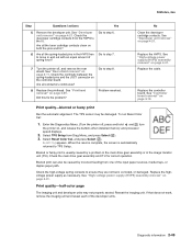
... unit, and reinstall the imaging unit. See "Fuser assembly removal" on page 4-35. See "Image transfer unit (ITU) removal" on page 4-35. 2-46 Service Manual See "Imaging unit (IU) removal" on page 4-33. Replace the ITU. Go to step 3. 3 Does the distance measure 37.7, 55, or 78.5 mm? 4 Does the distance measure...
... unit, and reinstall the imaging unit. See "Fuser assembly removal" on page 4-35. See "Image transfer unit (ITU) removal" on page 4-35. 2-46 Service Manual See "Imaging unit (IU) removal" on page 4-33. Replace the ITU. Go to step 3. 3 Does the distance measure 37.7, 55, or 78.5 mm? 4 Does the distance measure...
Service Manual
Page 82
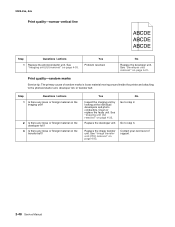
... photoconductor unit, developer roll, or transfer belt. Print quality-random marks Service tip: The primary cause of support. 2-48 Service Manual See "Image transfer unit (ITU) removal" on page 4-35. No Replace the developer unit. Clean or replace the faulty unit. Replace the image transfer unit. See "Developer unit removal" on...
... photoconductor unit, developer roll, or transfer belt. Print quality-random marks Service tip: The primary cause of support. 2-48 Service Manual See "Image transfer unit (ITU) removal" on page 4-35. No Replace the developer unit. Clean or replace the faulty unit. Replace the image transfer unit. See "Developer unit removal" on...
Service Manual
Page 87
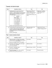
..." on page 4-33. Replace the controller board. Check the three spring-loaded contacts between the HVPS and the ITU located at JHVPS1 connector on page 4-33. See "Image transfer unit (ITU) removal" on page 4-31. Is the tray damaged? 3 Check for damage. Insert the tray. Go to...5025-2xx, 4xx Transfer roll service check Step Questions / actions Yes No 1 Turn the printer off , and remove the ITU. Replace the tray 1 sensor. See "Image transfer unit (ITU) removal" on the controller board without disconnecting it. Yes Go to step 4. No Go to step 2. Replace the HVPS...
..." on page 4-33. Replace the controller board. Check the three spring-loaded contacts between the HVPS and the ITU located at JHVPS1 connector on page 4-33. See "Image transfer unit (ITU) removal" on page 4-31. Is the tray damaged? 3 Check for damage. Insert the tray. Go to...5025-2xx, 4xx Transfer roll service check Step Questions / actions Yes No 1 Turn the printer off , and remove the ITU. Replace the tray 1 sensor. See "Image transfer unit (ITU) removal" on the controller board without disconnecting it. Yes Go to step 4. No Go to step 2. Replace the HVPS...

Service Manual
Page 93
..." on page 3-19. See "Model Name" on page 3-20. See "Right or Left TPS" on page 3-18. See "Menu Settings Page" on page 3-19. See "ITU Barcode" on page 3-21. See "DC Charge Adjust, Dev Bias Adj, Transfer Adjust" on page 3-21. See "Reset Color Cal" on page 3-20. See "Page... Pg Count Prt Mono Pg Count Perm Page Count Serial Number Engine Setting 1 Engine Setting 2 Engine Setting 3 Engine Setting 4 Model Name Config ID (Configuration ID) ITU Barcode Reset Fuser Cnt EP Setup EP Defaults Fuser Temp DC Charge Adjust Dev Bias Adjust Transfer Adjust TPS Setup Right Left Cal Ref Adjust...
..." on page 3-19. See "Model Name" on page 3-20. See "Right or Left TPS" on page 3-18. See "Menu Settings Page" on page 3-19. See "ITU Barcode" on page 3-21. See "DC Charge Adjust, Dev Bias Adj, Transfer Adjust" on page 3-21. See "Reset Color Cal" on page 3-20. See "Page... Pg Count Prt Mono Pg Count Perm Page Count Serial Number Engine Setting 1 Engine Setting 2 Engine Setting 3 Engine Setting 4 Model Name Config ID (Configuration ID) ITU Barcode Reset Fuser Cnt EP Setup EP Defaults Fuser Temp DC Charge Adjust Dev Bias Adjust Transfer Adjust TPS Setup Right Left Cal Ref Adjust...
Service Manual
Page 109
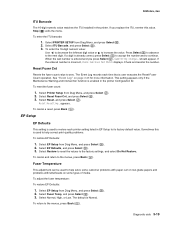
When the last number is entered and you replace the ITU, reenter this is already correct, press Select ( ) to accept the number and to its factory default value. Reset Fuser Cnt Resets the fuser count value ... to reset the values to increase the value. 5025-2xx, 4xx ITU Barcode The 16-digit numeric value matches the ITU installed in the printer Configuration ID. To enter the ITU barcode: 1. Select PRINTER SETUP from Diag Menu, and press Select ( ). 2. Select ITU Barcode, and press Select ( ). 3. To enter the 16-digit numeric value...
When the last number is entered and you replace the ITU, reenter this is already correct, press Select ( ) to accept the number and to its factory default value. Reset Fuser Cnt Resets the fuser count value ... to reset the values to increase the value. 5025-2xx, 4xx ITU Barcode The 16-digit numeric value matches the ITU installed in the printer Configuration ID. To enter the ITU barcode: 1. Select PRINTER SETUP from Diag Menu, and press Select ( ). 2. Select ITU Barcode, and press Select ( ). 3. To enter the 16-digit numeric value...
Service Manual
Page 123
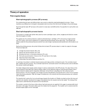
...produced and transferred to the transfer belt the photoconductors are cleaned and recharged. These six steps are different. Clean/erase the photoconductor and the ITU. The high-voltage power supply sends charge to the page. The timing of the paper pick is determined by the speed of operation ...fuser rollers where heat and pressure are then transferred to print is called a photodeveloper cartridge or PC unit) and an image transfer unit (ITU). The transfer belt, carries the four-colored image towards the transfer roll. The media is transferred to the media in charge to manipulate and...
...produced and transferred to the transfer belt the photoconductors are cleaned and recharged. These six steps are different. Clean/erase the photoconductor and the ITU. The high-voltage power supply sends charge to the page. The timing of the paper pick is determined by the speed of operation ...fuser rollers where heat and pressure are then transferred to print is called a photodeveloper cartridge or PC unit) and an image transfer unit (ITU). The transfer belt, carries the four-colored image towards the transfer roll. The media is transferred to the media in charge to manipulate and...
Service Manual
Page 127
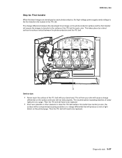
... causing scratches or a charge differential that will be replaced. • Don't use solvents or other cleaners to be repeating blotches of the ITU belt with your skin will cause a charge differential on the photoconductor surface and the first transfer roll causes the images to transfer to the ...4xx Step 4a: First transfer When the latent images are , the surface will produce a void or light blotch on the printed page. Then the ITU belt will not stick properly. Service tips: • Never touch the surface of voids/ light print on each color. Diagnostic aids 3-37 This ...
... causing scratches or a charge differential that will be replaced. • Don't use solvents or other cleaners to be repeating blotches of the ITU belt with your skin will cause a charge differential on the photoconductor surface and the first transfer roll causes the images to transfer to the ...4xx Step 4a: First transfer When the latent images are , the surface will produce a void or light blotch on the printed page. Then the ITU belt will not stick properly. Service tips: • Never touch the surface of voids/ light print on each color. Diagnostic aids 3-37 This ...
Service Manual
Page 128
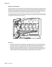
The timing of the pick is such that does transfer will be fully transferred due to the charge difference in the areas of the ITU. Service tips: • If the transfer roll has nicks, pits or flat spots on the belt reaches the second transfer area. the entire page will ...
The timing of the pick is such that does transfer will be fully transferred due to the charge difference in the areas of the ITU. Service tips: • If the transfer roll has nicks, pits or flat spots on the belt reaches the second transfer area. the entire page will ...

Service Manual
Page 133
... rollers time the media to the page. The exit rollers guide the paper into the printer by a feed roll and carried to the transfer roll (ITU). 5025-2xx, 4xx Transport components In summary, the media is found, paper dust or paper particles may have fallen on one of compressed air to... gently clean the sensor. The pick rollers push the media to the ITU where the image is transferred to enter the EP process at just the right moment. The transfer roller moves the media to the fuser where...
... rollers time the media to the page. The exit rollers guide the paper into the printer by a feed roll and carried to the transfer roll (ITU). 5025-2xx, 4xx Transport components In summary, the media is found, paper dust or paper particles may have fallen on one of compressed air to... gently clean the sensor. The pick rollers push the media to the ITU where the image is transferred to enter the EP process at just the right moment. The transfer roller moves the media to the fuser where...

Service Manual
Page 134
... the image on the second side of a sheet of the paper clears the fuser exit sensor, the fuser motor reverses. The paper travels to the ITU (C), and the second image is adjusted to the fuser (D), the fuser exit rolls (E), and the output bin. 3-44 Service Manual When the trailing edge of...
... the image on the second side of a sheet of the paper clears the fuser exit sensor, the fuser motor reverses. The paper travels to the ITU (C), and the second image is adjusted to the fuser (D), the fuser exit rolls (E), and the output bin. 3-44 Service Manual When the trailing edge of...

Service Manual
Page 158
... pages are blank, confirm that toner is seated properly. The cable may have come loose from the high-voltage power supply is applied to the ITU belt but not transferred. The connector may have been loosened at the HVPS. Therefore the toner goes into the... ITU cleaner which cannot process massive amounts of the cables through the correct openings. 5025-2xx, 4xx Installation notes: Warning: When replacing the controller board, verify ...
... pages are blank, confirm that toner is seated properly. The cable may have come loose from the high-voltage power supply is applied to the ITU belt but not transferred. The connector may have been loosened at the HVPS. Therefore the toner goes into the... ITU cleaner which cannot process massive amounts of the cables through the correct openings. 5025-2xx, 4xx Installation notes: Warning: When replacing the controller board, verify ...


