
Service Manual
Page 7
...When servicing this machine: • Move the machine to be used in this product. The ink is plugged into an electrical outlet. Keep the ink cartridges out of reach of this product is not intended to a suitable service area • Use a drop cloth (PN 1280055) under the machine &#...8226; Never disconnect ink lines while the printer is an electrical conductor. The ink contains permanent dyes that can stain clothing and furniture. Shorting and failure may not always be an increased risk...
...When servicing this machine: • Move the machine to be used in this product. The ink is plugged into an electrical outlet. Keep the ink cartridges out of reach of this product is not intended to a suitable service area • Use a drop cloth (PN 1280055) under the machine &#...8226; Never disconnect ink lines while the printer is an electrical conductor. The ink contains permanent dyes that can stain clothing and furniture. Shorting and failure may not always be an increased risk...

Service Manual
Page 9
...MAP 0140: Carriage Position MAP 0150: Carriage Motor Drive Data MAP 0160: Logic Board and Related Cables MAP 0170: Ink Cartridge MAP 0180: Ink Sensor MAP 0190: Ink Flow MAP 0200: Paper Feed Electrical MAP 0210: Paper Feed Mechanical MAP 0220:... Service Marks . About This Manual Related Publications Safety Information Ink Safety Notice General Information Description of the Printer Coated Paper Ink Cartridges . Operating Temperatures and Humidity Tools Using Printer Emulation Operator Panel Print Head Capping Adjusting the Print Head Position Lever Diagnostic Information MAP 0100: Start ....
...MAP 0140: Carriage Position MAP 0150: Carriage Motor Drive Data MAP 0160: Logic Board and Related Cables MAP 0170: Ink Cartridge MAP 0180: Ink Sensor MAP 0190: Ink Flow MAP 0200: Paper Feed Electrical MAP 0210: Paper Feed Mechanical MAP 0220:... Service Marks . About This Manual Related Publications Safety Information Ink Safety Notice General Information Description of the Printer Coated Paper Ink Cartridges . Operating Temperatures and Humidity Tools Using Printer Emulation Operator Panel Print Head Capping Adjusting the Print Head Position Lever Diagnostic Information MAP 0100: Start ....

Service Manual
Page 11
... Handling Carriage Shaft, Carriage Belt, and Carriage Ink Supply Power Supply Controller Board and Logic Board Electronic Modules (Assembly 4) Purge Unit Purge Unit Replacement Ink Cartridge Assembly Carriage Frame Paper Feed Pinch Roller Base Unit Pickup Roller, Paper Lifting Plate Platen Paper Feed and Eject Rollers Paper Feed Motor Paper Sensor...
... Handling Carriage Shaft, Carriage Belt, and Carriage Ink Supply Power Supply Controller Board and Logic Board Electronic Modules (Assembly 4) Purge Unit Purge Unit Replacement Ink Cartridge Assembly Carriage Frame Paper Feed Pinch Roller Base Unit Pickup Roller, Paper Lifting Plate Platen Paper Feed and Eject Rollers Paper Feed Motor Paper Sensor...
Service Manual
Page 12
... Asserr bly 11: Carriaite Drive . A.sserr Lily 12: Carriar:je Drive Frame Assembly 13: Ink S 41ply Unit Assembly 14: Ink Return Unit Assembly 15: Ink Cartridge Interlock. Asserrbly 16: Sheettr ed Entry Assembly 17: Sheetfred Pinch Roller Assembly 18: Pape Heed/Eject Roller Assembly 19: ;Thee:feed Separation Assembly 20: Pape...
... Asserr bly 11: Carriaite Drive . A.sserr Lily 12: Carriar:je Drive Frame Assembly 13: Ink S 41ply Unit Assembly 14: Ink Return Unit Assembly 15: Ink Cartridge Interlock. Asserrbly 16: Sheettr ed Entry Assembly 17: Sheetfred Pinch Roller Assembly 18: Pape Heed/Eject Roller Assembly 19: ;Thee:feed Separation Assembly 20: Pape...
Service Manual
Page 14
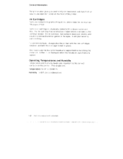
....MEl 43410111::4 the ini«:;aritridgE has an electronic label which i s se ised cIi the -iariiridgei sensor. fa prevent ink leaks. .ti ways ship the printer with the Carriage lacked in place. \Isla rmakie sure t ie lour print heads are : 'Temperature 15-7,:,i0c F)) liumidity 5.-95( .. (no condensation) '1-2 ... the ink ii..art-idges nstalled. Ms.:). A. but ioontains isoorcpyl alccihai and iinould not be swallowed or gotten in its own color islet. It will perir ar errly clothing.. Ink Cartridges :Etch one contains 31) grams of the printer. much as 77:10 pages ext colicir...
....MEl 43410111::4 the ini«:;aritridgE has an electronic label which i s se ised cIi the -iariiridgei sensor. fa prevent ink leaks. .ti ways ship the printer with the Carriage lacked in place. \Isla rmakie sure t ie lour print heads are : 'Temperature 15-7,:,i0c F)) liumidity 5.-95( .. (no condensation) '1-2 ... the ink ii..art-idges nstalled. Ms.:). A. but ioontains isoorcpyl alccihai and iinould not be swallowed or gotten in its own color islet. It will perir ar errly clothing.. Ink Cartridges :Etch one contains 31) grams of the printer. much as 77:10 pages ext colicir...

Service Manual
Page 21
... 2 16 2 18 2 22 2-24 2-26 2.30 2 34 2-42 2-46 2 -50 2-52 2-54 2 56 2-58 2-60 2-62 2-64 2-66 2 - 70 2.72 2 -74 2.75 Diagnostic Information 2-1 Ink Cartridge MAP 0180: Ink Sensor MAP 019O Ink Flow . Diagnostic Information MAP 0100: Start . . Logged Error code Operator Codes and Messages MAP 0120: Cover Open MAP...
... 2 16 2 18 2 22 2-24 2-26 2.30 2 34 2-42 2-46 2 -50 2-52 2-54 2 56 2-58 2-60 2-62 2-64 2-66 2 - 70 2.72 2 -74 2.75 Diagnostic Information 2-1 Ink Cartridge MAP 0180: Ink Sensor MAP 019O Ink Flow . Diagnostic Information MAP 0100: Start . . Logged Error code Operator Codes and Messages MAP 0120: Cover Open MAP...

Service Manual
Page 44
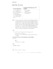
...eartricige. 003 Disconnect the CNID connector from the left connector card. I4 1161. is not used. (51:ep 003 continues,' 2-24 leivi Color ,Jelp rin e F'S 4079 HhA E], is susttect Check the ink cal( id ge detection resistor pad (top left of clearing cloths, or paper towels over the ...:;onneetcr end, secured vk it( a rubber band Keep the as em )ly on the link cartridge detection resister pa for e;wh color 'I5K to remove the ink cartridge assembly...
...eartricige. 003 Disconnect the CNID connector from the left connector card. I4 1161. is not used. (51:ep 003 continues,' 2-24 leivi Color ,Jelp rin e F'S 4079 HhA E], is susttect Check the ink cal( id ge detection resistor pad (top left of clearing cloths, or paper towels over the ...:;onneetcr end, secured vk it( a rubber band Keep the as em )ly on the link cartridge detection resister pa for e;wh color 'I5K to remove the ink cartridge assembly...

Service Manual
Page 45
WBLW 9WYWK 12 3 45 6 76 9 hui ILL AL CNID 8 7 I (K') K W 2 1 - (C') BL W Is the continuity correct? Yes No 004 Remove the ink cartridge assembly. Match pin numbers at both ends of pins 15K to 25K Ohms? Diagnostic Information 2-25 Yes No 4 (M ) R W 6 5 Y W 005 Replace the sensor cable. [006 Replace the ink cartridge sensor. 007] Replace the logic board. Check continuity on each set of the cable. Ink Cartridge 003 (continued) Is the resistance on the sensor cable.
WBLW 9WYWK 12 3 45 6 76 9 hui ILL AL CNID 8 7 I (K') K W 2 1 - (C') BL W Is the continuity correct? Yes No 004 Remove the ink cartridge assembly. Match pin numbers at both ends of pins 15K to 25K Ohms? Diagnostic Information 2-25 Yes No 4 (M ) R W 6 5 Y W 005 Replace the sensor cable. [006 Replace the ink cartridge sensor. 007] Replace the logic board. Check continuity on each set of the cable. Ink Cartridge 003 (continued) Is the resistance on the sensor cable.
Service Manual
Page 46
...Cian you remove al l ink cartrlddes, narefuhy (drain the ink .frord the lines into a plastic-lined waste can or aPsorbent mat al , then replace the cartridges and wrap a packet of ink: Remove the MI; (:artridge 2 Hold ng a :loth cier the sensor end, gently shake tie ink dge. rubber band...!M bry, it it recommended that you hear ink or cfEel ink movement in the cartridge? (es No CI02, RiecilacE the irk cidrtridge. 003 :Step 003 cc ntinues 2.26 IBM Color JElpri -:S 4079 HIV, S II , I•1 t II • 0 0 • 1•t+de i • ill,' M P II in Romp NI 000000 IIII00.10,I ...
...Cian you remove al l ink cartrlddes, narefuhy (drain the ink .frord the lines into a plastic-lined waste can or aPsorbent mat al , then replace the cartridges and wrap a packet of ink: Remove the MI; (:artridge 2 Hold ng a :loth cier the sensor end, gently shake tie ink dge. rubber band...!M bry, it it recommended that you hear ink or cfEel ink movement in the cartridge? (es No CI02, RiecilacE the irk cidrtridge. 003 :Step 003 cc ntinues 2.26 IBM Color JElpri -:S 4079 HIV, S II , I•1 t II • 0 0 • 1•t+de i • ill,' M P II in Romp NI 000000 IIII00.10,I ...

Service Manual
Page 47
... 6 pins 7 - 8 BR BLBR R BR Y BR K 1 2 3 4 5 6 7 8 [ I I (K) K / ----17., -\ BL ...J - 7 0 j --",(,C, *) R ....,(V Y _. ./ \ I 6 To push down the ink sensor: insert a thin screwdrver just above the ink cartridge assembly and below the paper lift plate, then push the ink sensor plunger down. '-"'" Magenta NN The voltage should be Low when the sensor is... Check the ink sensor by checking for 5 V between the pins designated for connector location. See page 4-2 for each cartridge sensor on (the center of the sensor is up), and High when the sensor is off (the center of the sensor...
... 6 pins 7 - 8 BR BLBR R BR Y BR K 1 2 3 4 5 6 7 8 [ I I (K) K / ----17., -\ BL ...J - 7 0 j --",(,C, *) R ....,(V Y _. ./ \ I 6 To push down the ink sensor: insert a thin screwdrver just above the ink cartridge assembly and below the paper lift plate, then push the ink sensor plunger down. '-"'" Magenta NN The voltage should be Low when the sensor is... Check the ink sensor by checking for 5 V between the pins designated for connector location. See page 4-2 for each cartridge sensor on (the center of the sensor is up), and High when the sensor is off (the center of the sensor...

Service Manual
Page 50
... the ink ;:a rridge assembly supply lines (As 1.1 3.-z: necessary. 2.30 IOM G lor Jetorirde ' f:S 4079 HMS III 4. Are all carriage !suppi r lines full of ink tram the ink cartridge. kr. Check, 3S many as possible durii ig the long. cleaning rat her than per ormini) a ... bow diagram on page 4.7 and the text on the following page. S:art I res • Carriage supply and 'Nesle • F"urge waste lines • Ink cartridge waste i i ies • Purge Unit • ink supply assembly. • Print Head kmportant: A long clearrng uses a significant amount of it k. I $4 ...
... the ink ;:a rridge assembly supply lines (As 1.1 3.-z: necessary. 2.30 IOM G lor Jetorirde ' f:S 4079 HMS III 4. Are all carriage !suppi r lines full of ink tram the ink cartridge. kr. Check, 3S many as possible durii ig the long. cleaning rat her than per ormini) a ... bow diagram on page 4.7 and the text on the following page. S:art I res • Carriage supply and 'Nesle • F"urge waste lines • Ink cartridge waste i i ies • Purge Unit • ink supply assembly. • Print Head kmportant: A long clearrng uses a significant amount of it k. I $4 ...

Service Manual
Page 51
... assembly connector? Yes No 0081 Replace the purge unit. 009 Is ink leaking from the ink cartridge assembly or into the bottom pan? Check and replace the ink cartridge assembly waste lines 4Asm 14-3) or ink cartridge, as necessary. (Step 011 continues) Diagnostic Information 2-31 Yes No 006 Replace the ink supply assembly...
... assembly connector? Yes No 0081 Replace the purge unit. 009 Is ink leaking from the ink cartridge assembly or into the bottom pan? Check and replace the ink cartridge assembly waste lines 4Asm 14-3) or ink cartridge, as necessary. (Step 011 continues) Diagnostic Information 2-31 Yes No 006 Replace the ink supply assembly...

Service Manual
Page 66
...Print Quality Symptom Explanation Print quality probterii;, missing clots. POSSiHe ink supply problern. This Symptom II Clogged ink ilines IN Print head ^^ Cartridge present sensor 001 YOU are here becal..isi:i ihe Print Sample Nozzle ind cates iTome nozzles may be plugoed. Is the print quality satisfactory...? No 003 Go to Step )05.. 004 End Ihe call. 005 (Step 005 continUes) 2-46 IBM color JI:tpr n :er F's 4079 HMS olliilliP1411111111.110W di III till 11a. 1.4 NI 1phisi , Yes No 002 Perform Long Cleaning and check print quality. Perform Normal ...
...Print Quality Symptom Explanation Print quality probterii;, missing clots. POSSiHe ink supply problern. This Symptom II Clogged ink ilines IN Print head ^^ Cartridge present sensor 001 YOU are here becal..isi:i ihe Print Sample Nozzle ind cates iTome nozzles may be plugoed. Is the print quality satisfactory...? No 003 Go to Step )05.. 004 End Ihe call. 005 (Step 005 continUes) 2-46 IBM color JI:tpr n :er F's 4079 HMS olliilliP1411111111.110W di III till 11a. 1.4 NI 1phisi , Yes No 002 Perform Long Cleaning and check print quality. Perform Normal ...

Service Manual
Page 67
...connectors loose, disconnected, or defective Check for the following conditions: • The carriage supply lines are always fi lled with a cloth, and gently shake the cartridge. Remove the suspected ink cartridge, cover the sensor end with ink.. (Step 011 continues) Diagnostic :nformation 2-47 Yes No 008 Replace the ink... cartridge. 009 - Perform a Long Cleaning, paying attention to the carriage supply lines, subtank ink levels, and carriage waste l ines. Make sure the platen is not ...
...connectors loose, disconnected, or defective Check for the following conditions: • The carriage supply lines are always fi lled with a cloth, and gently shake the cartridge. Remove the suspected ink cartridge, cover the sensor end with ink.. (Step 011 continues) Diagnostic :nformation 2-47 Yes No 008 Replace the ink... cartridge. 009 - Perform a Long Cleaning, paying attention to the carriage supply lines, subtank ink levels, and carriage waste l ines. Make sure the platen is not ...

Service Manual
Page 118
unrr.r mnxrx,"" Ixxll IMO*. Frame .S e pa rati on Sheet 3-44 3-4.7 3-49 3-49 3-50 3-52 3-53 3-54 3-55 3-56 .3-57 3-12 NB M Color lpf int .1r. '5 4079 HMS .111.10116114.1.1 :r•. Paper Feed and Ej i?ct Rollers Paper Feed Mat::' Paper Sensor . . M Remova.ls Ink Cartridge Assemt ly Carriage Frarne Paper Feet, Pinch Roller Ease Jnit Pick.uo Roller, Pap r Lifting Plate Platen . . . .
unrr.r mnxrx,"" Ixxll IMO*. Frame .S e pa rati on Sheet 3-44 3-4.7 3-49 3-49 3-50 3-52 3-53 3-54 3-55 3-56 .3-57 3-12 NB M Color lpf int .1r. '5 4079 HMS .111.10116114.1.1 :r•. Paper Feed and Ej i?ct Rollers Paper Feed Mat::' Paper Sensor . . M Remova.ls Ink Cartridge Assemt ly Carriage Frarne Paper Feet, Pinch Roller Ease Jnit Pick.uo Roller, Pap r Lifting Plate Platen . . . .

Service Manual
Page 149
... ty spreading both black latches outward. Lift out the purge unit as far as possible. 2. Separate the gray/black ink tube joint from the ink cartridge assembly. Wrap the nk tube ends in cleaning cloth ar d secure with a rubber band. Wrap the ink tube ends in cleaning cloth and se.Tu... to sp II ,nl< from the tubes. FJ Drain joint Ink tubes of purge unit The purge unit can now be l ifted out of the printer, if necessary Repair laformatior 3-43
... ty spreading both black latches outward. Lift out the purge unit as far as possible. 2. Separate the gray/black ink tube joint from the ink cartridge assembly. Wrap the nk tube ends in cleaning cloth ar d secure with a rubber band. Wrap the ink tube ends in cleaning cloth and se.Tu... to sp II ,nl< from the tubes. FJ Drain joint Ink tubes of purge unit The purge unit can now be l ifted out of the printer, if necessary Repair laformatior 3-43
Service Manual
Page 150
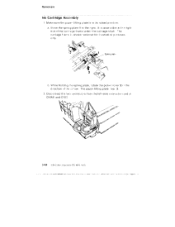
...2. AIM,:II fi ll 41ri 'MAK.irg 141f ig r • 41 awl, aipram .allkItla It... . .11Ki4 N.:I 'imam a., ammomao , Rernova Is Ink Cartridge Ass,arnbly 1. R% acce!;:sible at tor cmd al: CNINI< and C,NID. Disconnect the twp ,'.onnectors from the left-side tionn at tn.a right end of... the arrow. Mlove the sprir g plate 1 to the right. CalOr ...letprini et PS ,4079 HMIS . • .1*.i...4111.1•11.1. wbmhddng6lsmmgNGm rotate the picker roller :2 -1 the direction of the carriage frame under the carriage shaft The carriage:tram...
...2. AIM,:II fi ll 41ri 'MAK.irg 141f ig r • 41 awl, aipram .allkItla It... . .11Ki4 N.:I 'imam a., ammomao , Rernova Is Ink Cartridge Ass,arnbly 1. R% acce!;:sible at tor cmd al: CNINI< and C,NID. Disconnect the twp ,'.onnectors from the left-side tionn at tn.a right end of... the arrow. Mlove the sprir g plate 1 to the right. CalOr ...letprini et PS ,4079 HMIS . • .1*.i...4111.1•11.1. wbmhddng6lsmmgNGm rotate the picker roller :2 -1 the direction of the carriage frame under the carriage shaft The carriage:tram...

Service Manual
Page 151
Disconnect the purge ink waste tubes from the side frame and hook it to prevent ink spillage. Drain joint Ink tubes of the tubes in their correct positions. The ink cartridges are color-coded and can only be installed in cleaning cloth, secured with a rubber band, to the top of the carriage frame as shown below. 7 -1t 5. Disconnect the carriage ink supply joint from the side frame Wrap the end of purge unit 4. Repair Information 3-45 Lay them in a safe place where they will not stain furniture or clothing. Remove the ink cartridges. Removals 3.
Disconnect the purge ink waste tubes from the side frame and hook it to prevent ink spillage. Drain joint Ink tubes of the tubes in their correct positions. The ink cartridges are color-coded and can only be installed in cleaning cloth, secured with a rubber band, to the top of the carriage frame as shown below. 7 -1t 5. Disconnect the carriage ink supply joint from the side frame Wrap the end of purge unit 4. Repair Information 3-45 Lay them in a safe place where they will not stain furniture or clothing. Remove the ink cartridges. Removals 3.

Service Manual
Page 152
...printE r :"S 4079 :MS • I.* , *N. 6.1111114411$411*11411I4,11III UN 41.1,k1INI, 141.1.8.1.$ 4, 4* * N NM *NO* N, Sill, Use a flat-blade si :::-iewdriyer to p -event. Insert the ink cartr dges into the ink compartment. .n a oloih over the connector eld and secure imth a rubber b and Placis the cartridge asseirnbly on ink... cloth, 1.46 IE31hA CL)lor ,Je- The bottom at the unit is drained c Wipe end of connecI r with the black cartridge e • slightly elevated to release the left latch wt ille the unit slightly. i Release the right latnh while (:f the ma;:hine. k leakage...
...printE r :"S 4079 :MS • I.* , *N. 6.1111114411$411*11411I4,11III UN 41.1,k1INI, 141.1.8.1.$ 4, 4* * N NM *NO* N, Sill, Use a flat-blade si :::-iewdriyer to p -event. Insert the ink cartr dges into the ink compartment. .n a oloih over the connector eld and secure imth a rubber b and Placis the cartridge asseirnbly on ink... cloth, 1.46 IE31hA CL)lor ,Je- The bottom at the unit is drained c Wipe end of connecI r with the black cartridge e • slightly elevated to release the left latch wt ille the unit slightly. i Release the right latnh while (:f the ma;:hine. k leakage...

Service Manual
Page 169
...r"--- 7 CARRIAGE cl ,) DIE=Mart 5i0 coCrA.nBoLE WIN Brown) ZI UN p iv) (-)L. P-nter head Printer head L (IA) I Right ' CARRIAGE connecto orC'nAgti_Ea 2B0rPowiNn) • Caro ,I "T Pr,rter head... UNIT Carriage drive motor B Paper feed motor U CNPE fj PAPER SENSOR CABLE 013 Paper empty sensor I Cartridge Out Sensor Unit K' 2 av BL 3 OND BR 4 .5V R GNO BR a .6V V... Carnage card aper w do sensor ENCODER UNIT KEY: WIRE COLORS BL = Blue BR = Brown G = Gray K = BlaCk 0 = Orange R = Red V = Violet W = White Y = Yellow KEY: INK LINE COLORS • = Cyan (Blue) • = Black W ...
...r"--- 7 CARRIAGE cl ,) DIE=Mart 5i0 coCrA.nBoLE WIN Brown) ZI UN p iv) (-)L. P-nter head Printer head L (IA) I Right ' CARRIAGE connecto orC'nAgti_Ea 2B0rPowiNn) • Caro ,I "T Pr,rter head... UNIT Carriage drive motor B Paper feed motor U CNPE fj PAPER SENSOR CABLE 013 Paper empty sensor I Cartridge Out Sensor Unit K' 2 av BL 3 OND BR 4 .5V R GNO BR a .6V V... Carnage card aper w do sensor ENCODER UNIT KEY: WIRE COLORS BL = Blue BR = Brown G = Gray K = BlaCk 0 = Orange R = Red V = Violet W = White Y = Yellow KEY: INK LINE COLORS • = Cyan (Blue) • = Black W ...


