Setup Guide
Page 1
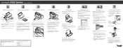
... floppy drive). Machine type number Serial number 1 Turn the printer so the back faces you. 2 Hook the bottom of the paper support under the lip on the back of paper. 1 Open the paper load door. 2 Extend the paper exit tray. 3 Insert paper. 4 For different size paper, squeeze the left paper guide release lever and move to the correct paper size. 5 Close the paper load door. Lexmark 2050 Series Color Jetprinter 1 Unpack your floppy drive). 4 From the Start menu choose Settings, then choose Printers. 5 From the Printers folder, double...
... floppy drive). Machine type number Serial number 1 Turn the printer so the back faces you. 2 Hook the bottom of the paper support under the lip on the back of paper. 1 Open the paper load door. 2 Extend the paper exit tray. 3 Insert paper. 4 For different size paper, squeeze the left paper guide release lever and move to the correct paper size. 5 Close the paper load door. Lexmark 2050 Series Color Jetprinter 1 Unpack your floppy drive). 4 From the Start menu choose Settings, then choose Printers. 5 From the Printers folder, double...
Setup Guide
Page 2
... standards with the use of specific Lexmark components. Lexington, KY 40511-1876 USA • This product is a trademark of Lexmark International, Inc. 8 Use the printer software You can use the Lexmark 2050 Series printer software to: • change printer settings • install and align print cartridges • monitor print jobs and print cartridge ink levels • control jobs in the print queue • choose different sizes and types of paper • print from Windows or DOS applications • reset printer defaults Open the Online Guide In the Online Guide, you can find...
... standards with the use of specific Lexmark components. Lexington, KY 40511-1876 USA • This product is a trademark of Lexmark International, Inc. 8 Use the printer software You can use the Lexmark 2050 Series printer software to: • change printer settings • install and align print cartridges • monitor print jobs and print cartridge ink levels • control jobs in the print queue • choose different sizes and types of paper • print from Windows or DOS applications • reset printer defaults Open the Online Guide In the Online Guide, you can find...

Service Manual
Page 3
... Table 2-3 Symptom Tables 2-4 Service Checks 2-6 Envelope Feed Service Check 2-6 First Print Line Service Check 2-6 Maintenance Station Service Check 2-7 Paper Feed Service Check 2-8 Paper Path Service Check 2-11 Parallel Port Service Check 2-12 Power Service Check 2-12 Print Quality Service Check 2-13 Transport Service Check 2-15 Diagnostic Aids 3-1 Encoder Sensor Test 3-1 Paper Sensor Test 3-2 Parallel Port Test 3-3 Print NVRAM Contents 3-4 Test Page 3-5 Repair Information 4-1 Handling ESD-Sensitive Parts 4-1 Adjustments 4-2 Removal Procedures 4-2 Releasing Plastic...
... Table 2-3 Symptom Tables 2-4 Service Checks 2-6 Envelope Feed Service Check 2-6 First Print Line Service Check 2-6 Maintenance Station Service Check 2-7 Paper Feed Service Check 2-8 Paper Path Service Check 2-11 Parallel Port Service Check 2-12 Power Service Check 2-12 Print Quality Service Check 2-13 Transport Service Check 2-15 Diagnostic Aids 3-1 Encoder Sensor Test 3-1 Paper Sensor Test 3-2 Parallel Port Test 3-3 Print NVRAM Contents 3-4 Test Page 3-5 Repair Information 4-1 Handling ESD-Sensitive Parts 4-1 Adjustments 4-2 Removal Procedures 4-2 Releasing Plastic...

Service Manual
Page 5
... contains error indicator table, symptom table, and service checks used to identify the connector locations and test points on the printer. 6. Connector Locations uses illustrations to isolate failing field replaceable units (FRUs). 3. Therefore, replacement parts must have the identical or equivalent characteristics as general environmental and safety instructions. 2. Preface v Parts Catalog contains illustrations and part numbers for making printer adjustments and removing and installing FRUs. 5. Safety Information • The maintenance information...
... contains error indicator table, symptom table, and service checks used to identify the connector locations and test points on the printer. 6. Connector Locations uses illustrations to isolate failing field replaceable units (FRUs). 3. Therefore, replacement parts must have the identical or equivalent characteristics as general environmental and safety instructions. 2. Preface v Parts Catalog contains illustrations and part numbers for making printer adjustments and removing and installing FRUs. 5. Safety Information • The maintenance information...

Service Manual
Page 9
... alignment adjustments after replacing a print cartridge. This printer can be serviced without changing printheads. General Information 1-1 The black cartridge has a total of 48 nozzles and installs on the left. not printing) • 12 Watts - The user is directed, in the Printer Control program, to perform the head to the printer • 7.5 Watts - Use the error indicator charts, symptom index, service checks, and diagnostic aids to the correct field replaceable unit (FRU) or part. 1. General Information The Color Jetprinter 2050...
... alignment adjustments after replacing a print cartridge. This printer can be serviced without changing printheads. General Information 1-1 The black cartridge has a total of 48 nozzles and installs on the left. not printing) • 12 Watts - The user is directed, in the Printer Control program, to perform the head to the printer • 7.5 Watts - Use the error indicator charts, symptom index, service checks, and diagnostic aids to the correct field replaceable unit (FRU) or part. 1. General Information The Color Jetprinter 2050...

Service Manual
Page 11
... error. 1. Start Service error indications show as a series of blinks of blinks in the 'Error Indicator Table' on page 2-2. There is a pause between each series of the page. 2. Diagnostic Information Use the error indicator table, symptom tables, service checks, and diagnostic aids to clear the error indicator. Run the 'Test Page' on page 3-4. Unplug the printer to determine the failing part. The last error appears at the bottom of blinks. Run the 'Print NVRAM Contents' on page...
... error. 1. Start Service error indications show as a series of blinks of blinks in the 'Error Indicator Table' on page 2-2. There is a pause between each series of the page. 2. Diagnostic Information Use the error indicator table, symptom tables, service checks, and diagnostic aids to clear the error indicator. Run the 'Test Page' on page 3-4. Unplug the printer to determine the failing part. The last error appears at the bottom of blinks. Run the 'Print NVRAM Contents' on page...

Service Manual
Page 12
.... Power-On Self Test (POST) Sequence When you turn . 4. The carrier moves over the maintenance station and seals the printheads. 3. If your printer on and check for a correct POST operation by observing the following table and take the indicated action. Replace the Code Module and/or system board. Go to the 'Transport Service Check' on it performs a POST. The paper feed gears turn the printer on page...
.... Power-On Self Test (POST) Sequence When you turn . 4. The carrier moves over the maintenance station and seals the printheads. 3. If your printer on and check for a correct POST operation by observing the following table and take the indicated action. Replace the Code Module and/or system board. Go to the 'Transport Service Check' on it performs a POST. The paper feed gears turn the printer on page...

Service Manual
Page 13
POST Symptom Table Symptom No Power light and no motors run Feeds paper Paper feed gears do not turn Carrier doesn't move Carrier slams side frame Action Go to the 'First Print Line Service Check' on page 2-6. Go to the 'Power Service Check' on page 2-8. Diagnostic Information 2-3 Go to the 'Paper Feed Service Check' on page 2-12. Go to the 'Transport Service Check' on page 2-15. Go to the 'Transport Service Check' on page 2-15.
POST Symptom Table Symptom No Power light and no motors run Feeds paper Paper feed gears do not turn Carrier doesn't move Carrier slams side frame Action Go to the 'First Print Line Service Check' on page 2-6. Go to the 'Power Service Check' on page 2-8. Diagnostic Information 2-3 Go to the 'Paper Feed Service Check' on page 2-12. Go to the 'Transport Service Check' on page 2-15. Go to the 'Transport Service Check' on page 2-15.
Service Manual
Page 15
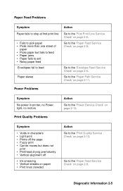
... sheet of paper • Picks paper but does not print • Printhead drying prematurely • Vertical alignment off the page • Fuzzy print • Carrier moves but fails to feed • Paper jams • Paper fails to exit • Noisy paper feed Envelopes fail to feed Paper skews Action Go to the 'First Print Line Service Check' on page 2-6. Go to the 'Print Quality Service Check' on page 2-8. Symptom • Voids in printer, no Power light, no motors Print Quality Problems Action Go to the 'Paper Feed Service Check' on page...
... sheet of paper • Picks paper but does not print • Printhead drying prematurely • Vertical alignment off the page • Fuzzy print • Carrier moves but fails to feed • Paper jams • Paper fails to exit • Noisy paper feed Envelopes fail to feed Paper skews Action Go to the 'First Print Line Service Check' on page 2-6. Go to the 'Print Quality Service Check' on page 2-8. Symptom • Voids in printer, no Power light, no motors Print Quality Problems Action Go to the 'Paper Feed Service Check' on page...

Service Manual
Page 18
... voltage is being used. • Check for static in the sheet feeder. • Be sure the correct type of paper is not present, check for motor pins shorted to the motor housing. If you still have paper jam problems, continue with the service check. Paper Feed Service Check If your printer does have a paper jam problem, examine it for the following before you begin the service check: • Check the entire paper path for...
... voltage is being used. • Check for static in the sheet feeder. • Be sure the correct type of paper is not present, check for motor pins shorted to the motor housing. If you still have paper jam problems, continue with the service check. Paper Feed Service Check If your printer does have a paper jam problem, examine it for the following before you begin the service check: • Check the entire paper path for...

Service Manual
Page 21
... correct type of -Forms Flag & Spring • Pick Rollers • Envelope Bucklers • All parts inside the left and right edge guides. FRU Action 1 Large and Small Feed Rollers Check for wear and binds. 2 Small Feed Roller Check for binds or damage. Diagnostic Information 2-11 Paper Path Service Check Examine the printer for the following for wear or damage: 5 End-of paper is being used...
... correct type of -Forms Flag & Spring • Pick Rollers • Envelope Bucklers • All parts inside the left and right edge guides. FRU Action 1 Large and Small Feed Rollers Check for wear and binds. 2 Small Feed Roller Check for binds or damage. Diagnostic Information 2-11 Paper Path Service Check Examine the printer for the following for wear or damage: 5 End-of paper is being used...

Service Manual
Page 23
... pattern shown below, replace the system board. 4 Maintenance Station If there is a single break or random breaks in the system board and check the following : • Check the gold-plated contacts, on page 3-5. Print Quality Service Check FRU 1 Print Cartridge 2 Printhead Carrier Assembly 3 System Board Printhead Cable Rubber Backer Action Be sure the printer contains good print cartridges. Look for a break in the maintenance station. You may need to remove the cable...
... pattern shown below, replace the system board. 4 Maintenance Station If there is a single break or random breaks in the system board and check the following : • Check the gold-plated contacts, on page 3-5. Print Quality Service Check FRU 1 Print Cartridge 2 Printhead Carrier Assembly 3 System Board Printhead Cable Rubber Backer Action Be sure the printer contains good print cartridges. Look for a break in the maintenance station. You may need to remove the cable...

Service Manual
Page 24
... wear or dirt. Check the following : • Correct type of paper is directed, through the Printer Control program, to perform the head to carrier frame engagement, the carrier guide rod and carrier bearing surfaces should be adjusted by performing the bidirectional alignment. FRU 5 Paper Feed 6 Transport 7 Alignment Action Ink smudging and smearing can be caused by problems in the paper feed area. Blurred print and voids can be...
... wear or dirt. Check the following : • Correct type of paper is directed, through the Printer Control program, to perform the head to carrier frame engagement, the carrier guide rod and carrier bearing surfaces should be adjusted by performing the bidirectional alignment. FRU 5 Paper Feed 6 Transport 7 Alignment Action Ink smudging and smearing can be caused by problems in the paper feed area. Blurred print and voids can be...

Service Manual
Page 25
... dirt. 6 Printhead Cable Be sure connector J4 is incorrect, replace the motor. Disconnect the transport motor (J6) from the system board. Transport Service Check FRU Action 1 Transport Motor Check the motor for worn, loose or broken parts. If you cannot enter the test, replace the system board. Check for binds, or loose motor pulley. Encoder Strip Encoder Card System Board 7 Maintenance Station...
... dirt. 6 Printhead Cable Be sure connector J4 is incorrect, replace the motor. Disconnect the transport motor (J6) from the system board. Transport Service Check FRU Action 1 Transport Motor Check the motor for worn, loose or broken parts. If you cannot enter the test, replace the system board. Check for binds, or loose motor pulley. Encoder Strip Encoder Card System Board 7 Maintenance Station...

Service Manual
Page 27
... paper through the sensor. The voltage should go from +5 V dc to the encoder card. If the symptom remains, replace the printhead cable. Diagnostic Aids 3-1 Diagnostic Aids Use these diagnostic test procedures to allow you pass a piece of the encoder card connector. 1. The power light blinks as you to manually move the carrier to make this check again. If the printhead cable is working correctly. Turn the printer off the printer and remove the...
... paper through the sensor. The voltage should go from +5 V dc to the encoder card. If the symptom remains, replace the printhead cable. Diagnostic Aids 3-1 Diagnostic Aids Use these diagnostic test procedures to allow you pass a piece of the encoder card connector. 1. The power light blinks as you to manually move the carrier to make this check again. If the printhead cable is working correctly. Turn the printer off the printer and remove the...

Service Manual
Page 28
... power light blinks continually. 6. paper is in sensor • Off - Remove the front cover. 3. The light change from the maintenance station. 7. Disconnect the transport motor connector J-6 at the system board. 4. As paper is inserted and removed from the paper switch, the light should change indicates the position of the switch has changed. 3-2 Turn the printer off . After a few seconds, the power light blinks 1 time. Release the carrier and insert paper into the manual feed slot. Paper Sensor Test This test checks the paper sensor...
... power light blinks continually. 6. paper is in sensor • Off - Remove the front cover. 3. The light change from the maintenance station. 7. Disconnect the transport motor connector J-6 at the system board. 4. As paper is inserted and removed from the paper switch, the light should change indicates the position of the switch has changed. 3-2 Turn the printer off . After a few seconds, the power light blinks 1 time. Release the carrier and insert paper into the manual feed slot. Paper Sensor Test This test checks the paper sensor...

Service Manual
Page 29
... intermittent problems exist. Irregularity of the blinking of the power light, is turned off and unplug the machine. 2. A failure occurs if the power light does blinks. Position the left edge of the printhead carrier at the center of an intermittent problem. This test should run the test: 1. Turn the printer on if the test runs successfully. Install the wrap plug in the parallel port before you start the test.
... intermittent problems exist. Irregularity of the blinking of the power light, is turned off and unplug the machine. 2. A failure occurs if the power light does blinks. Position the left edge of the printhead carrier at the center of an intermittent problem. This test should run the test: 1. Turn the printer on if the test runs successfully. Install the wrap plug in the parallel port before you start the test.
Service Manual
Page 31
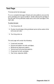
... the printhead carrier at the center of the left side of black and color patterns, be sure the print cartridges are in the right side. Install a black print cartridge in the left -most exit roller. 3. The test page will contain the following: • Code level and date • Nozzle test pattern for both cartridges • Bidirectional alignment pattern • Vertical and horizontal test patterns • Purge test for both cartridges • Text (Color Jetprinter 2050) Diagnostic Aids 3-5 Test Page This test prints the test page.
... the printhead carrier at the center of the left side of black and color patterns, be sure the print cartridges are in the right side. Install a black print cartridge in the left -most exit roller. 3. The test page will contain the following: • Code level and date • Nozzle test pattern for both cartridges • Bidirectional alignment pattern • Vertical and horizontal test patterns • Purge test for both cartridges • Text (Color Jetprinter 2050) Diagnostic Aids 3-5 Test Page This test prints the test page.

Service Manual
Page 34
Adjustments The user is latched. 4-2 The latches break easily; Removal Procedures The following procedures are arranged according to the name of the parts are held in the Printer Control program, to perform the head to which it is directed, in place with plastic latches. release them carefully. Releasing Plastic Latches Many of the printer part discussed. Unplug the power cord before removing any parts. To remove such parts, press the hook end of the latch away from the part to head and bidirectional alignment adjustments after replacing a print cartridge.
Adjustments The user is latched. 4-2 The latches break easily; Removal Procedures The following procedures are arranged according to the name of the parts are held in the Printer Control program, to perform the head to which it is directed, in place with plastic latches. release them carefully. Releasing Plastic Latches Many of the printer part discussed. Unplug the power cord before removing any parts. To remove such parts, press the hook end of the latch away from the part to head and bidirectional alignment adjustments after replacing a print cartridge.
Service Manual
Page 81
... Frame Assembly 4-13 Paper Deflector 4-17 Paper Feed Motor 4-14 Paper Flap 4-21 Paper Guide 4-14 Paper Load Door 4-16 Paper Load Shaft 4-6 Pick Roll Hub 4-16 Pick Roll Shaft 4-16 Power Supply 4-16 Printhead Cable 4-17 Printhead Carrier 4-19 Printhead Cradle 4-17 Printhead Rubber Backer 4-19 Rear Cover 4-20 Right Side Frame 4-20 Small Feed Roll Shaft 4-21 Small Feed Rollers 4-21 Star Roller 4-21 System Board 4-21 Repair Information 4-1 S Safety Information v Service Checks Envelope Feed 2-6 First Print Line 2-6 Maintenance Station 2-7
... Frame Assembly 4-13 Paper Deflector 4-17 Paper Feed Motor 4-14 Paper Flap 4-21 Paper Guide 4-14 Paper Load Door 4-16 Paper Load Shaft 4-6 Pick Roll Hub 4-16 Pick Roll Shaft 4-16 Power Supply 4-16 Printhead Cable 4-17 Printhead Carrier 4-19 Printhead Cradle 4-17 Printhead Rubber Backer 4-19 Rear Cover 4-20 Right Side Frame 4-20 Small Feed Roll Shaft 4-21 Small Feed Rollers 4-21 Star Roller 4-21 System Board 4-21 Repair Information 4-1 S Safety Information v Service Checks Envelope Feed 2-6 First Print Line 2-6 Maintenance Station 2-7


