
Service Manual
Page 1
1000 Color Jetprinter™ 1100 Color Jetprinter 4096-00X • Table of Contents • Start Diagnostics • Safety and Notices • Trademarks • Index • Manuals Menu Lexmark and Lexmark with diamond design are trademarks of Lexmark International, Inc., registered in the United States and/or other countries.
1000 Color Jetprinter™ 1100 Color Jetprinter 4096-00X • Table of Contents • Start Diagnostics • Safety and Notices • Trademarks • Index • Manuals Menu Lexmark and Lexmark with diamond design are trademarks of Lexmark International, Inc., registered in the United States and/or other countries.

Service Manual
Page 2
... Data and Computer Software clause at the back of the information you supply in certain transactions, therefore, this product by calling 1-800-553-9727. these changes will be incorporated in the products or the programs described may use or distribute any ...RIGHTS This software and documentation are trademarks of Lexmark International, Inc. Color Jetprinter is provided at DFARS 252.227-7013 and in the United States and/or other countries, contact your point of their respective owners. © Copyright Lexmark International, Inc. 1997, 1998. Improvements or changes in ...
... Data and Computer Software clause at the back of the information you supply in certain transactions, therefore, this product by calling 1-800-553-9727. these changes will be incorporated in the products or the programs described may use or distribute any ...RIGHTS This software and documentation are trademarks of Lexmark International, Inc. Color Jetprinter is provided at DFARS 252.227-7013 and in the United States and/or other countries, contact your point of their respective owners. © Copyright Lexmark International, Inc. 1997, 1998. Improvements or changes in ...

Service Manual
Page 3
... 2-1 Start 2-1 Power-On Self Test (POST) Sequence 2-1 Symptom Tables 2-2 POST Symptom Table 2-4 Service Checks 2-5 Carrier Transport Service Check 2-5 Envelope Feed Service Check 2-6 Maintenance Station Service Check 2-7 Paper Feed Service Check 2-8 Paper Path Service Check 2-10 Power Service Check 2-11 Print Quality Service Check 2-12 Diagnostic Aids 3-1 Repair Information 4-1 Handling ESD-Sensitive Parts 4-1 Adjustments 4-2 Removal Procedures 4-2 Releasing Plastic Latches 4-2 Access Cover Removal 4-2 Base and Sheet Feed Assembly Removal 4-2 Carrier Belt Removal...
... 2-1 Start 2-1 Power-On Self Test (POST) Sequence 2-1 Symptom Tables 2-2 POST Symptom Table 2-4 Service Checks 2-5 Carrier Transport Service Check 2-5 Envelope Feed Service Check 2-6 Maintenance Station Service Check 2-7 Paper Feed Service Check 2-8 Paper Path Service Check 2-10 Power Service Check 2-11 Print Quality Service Check 2-12 Diagnostic Aids 3-1 Repair Information 4-1 Handling ESD-Sensitive Parts 4-1 Adjustments 4-2 Removal Procedures 4-2 Releasing Plastic Latches 4-2 Access Cover Removal 4-2 Base and Sheet Feed Assembly Removal 4-2 Carrier Belt Removal...
Service Manual
Page 11
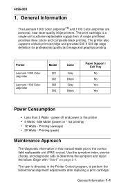
... printing. Idle Mode (power on page 2-1. The user is a single-unit customer replaceable supply item. Printer Lexmark 1000 Color Jetprinter Lexmark 1100 Color Jetprinter Model 001 002 003 004 Color Gray Black Gray Black Paper Support / Exit Tray No No Yes Yes Power Consumption • Less than 3 Watts - Begin with "Start" on - General Information 1-1 Printing (average) • 20 Watts - The print cartridge is directed, in this manual leads you to perform the bidirectional alignment adjustments after replacing a print cartridge. Use the symptom index, service checks...
... printing. Idle Mode (power on page 2-1. The user is a single-unit customer replaceable supply item. Printer Lexmark 1000 Color Jetprinter Lexmark 1100 Color Jetprinter Model 001 002 003 004 Color Gray Black Gray Black Paper Support / Exit Tray No No Yes Yes Power Consumption • Less than 3 Watts - Begin with "Start" on - General Information 1-1 Printing (average) • 20 Watts - The print cartridge is directed, in this manual leads you to perform the bidirectional alignment adjustments after replacing a print cartridge. Use the symptom index, service checks...

Service Manual
Page 13
Turn your machine does not complete POST, use the symptom tables and service checks in chapter 2 to determine the failing part. All motors stop. If your machine on it performs a POST. After 30 seconds the carrier moves over the maintenance station and caps the printhead. 4. Diagnostic Information Start Power-On Self Test (POST) Sequence When you turn . 3. The paper feed gears turn the printer on and check for a correct POST operation by observing the following: 1. Diagnostic Information 2-1 4096-00X 2. The carrier moves. 2.
Turn your machine does not complete POST, use the symptom tables and service checks in chapter 2 to determine the failing part. All motors stop. If your machine on it performs a POST. After 30 seconds the carrier moves over the maintenance station and caps the printhead. 4. Diagnostic Information Start Power-On Self Test (POST) Sequence When you turn . 3. The paper feed gears turn the printer on and check for a correct POST operation by observing the following: 1. Diagnostic Information 2-1 4096-00X 2. The carrier moves. 2.
Service Manual
Page 14
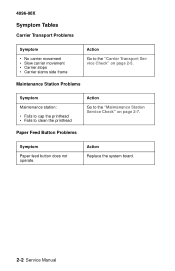
Maintenance Station Problems Symptom Maintenance station: • Fails to cap the printhead • Fails to clean the printhead Paper Feed Button Problems Action Go to the "Carrier Transport Service Check" on page 2-7. Symptom Paper feed button does not operate. 4096-00X Symptom Tables Carrier Transport Problems Symptom • No carrier movement • Slow carrier movement • Carrier stops • Carrier slams side frame Action Go to the "Maintenance Station Service Check" on page 2-5. Action Replace the system board. 2-2 Service Manual
Maintenance Station Problems Symptom Maintenance station: • Fails to cap the printhead • Fails to clean the printhead Paper Feed Button Problems Action Go to the "Carrier Transport Service Check" on page 2-7. Symptom Paper feed button does not operate. 4096-00X Symptom Tables Carrier Transport Problems Symptom • No carrier movement • Slow carrier movement • Carrier stops • Carrier slams side frame Action Go to the "Maintenance Station Service Check" on page 2-5. Action Replace the system board. 2-2 Service Manual
Service Manual
Page 15
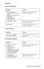
... • Light print • Prints off the page • Fuzzy print • Carrier moves but fails to feed • Paper jams • Paper fails to exit • Noisy paper feed Envelopes fail to feed Paper skews Power Problems Action Go to the "Paper Feed Service Check" on page 2-8. 4096-00X Paper Feed Problems Symptom • Fails to pick paper • Picks more than one sheet of paper • Picks paper but no print • Printhead drys prematurely • Colors print incorrectly • Vertical alignment off • Ink smearing...
... • Light print • Prints off the page • Fuzzy print • Carrier moves but fails to feed • Paper jams • Paper fails to exit • Noisy paper feed Envelopes fail to feed Paper skews Power Problems Action Go to the "Paper Feed Service Check" on page 2-8. 4096-00X Paper Feed Problems Symptom • Fails to pick paper • Picks more than one sheet of paper • Picks paper but no print • Printhead drys prematurely • Colors print incorrectly • Vertical alignment off • Ink smearing...
Service Manual
Page 16
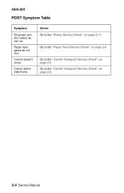
Go to the "Carrier Transport Service Check" on page 2-5. 2-4 Service Manual Go to the "Paper Feed Service Check" on page 2-8. Go to the "Power Service Check" on page 2-11. 4096-00X POST Symptom Table Symptom No power and the motors do not run Paper feed gears do not turn Carrier doesn't move Carrier slams side frame Action Go to the "Carrier Transport Service Check" on page 2-5.
Go to the "Carrier Transport Service Check" on page 2-5. 2-4 Service Manual Go to the "Paper Feed Service Check" on page 2-8. Go to the "Power Service Check" on page 2-11. 4096-00X POST Symptom Table Symptom No power and the motors do not run Paper feed gears do not turn Carrier doesn't move Carrier slams side frame Action Go to the "Carrier Transport Service Check" on page 2-5.
Service Manual
Page 18
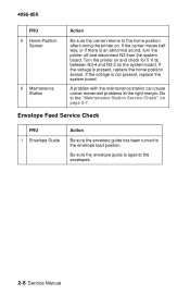
... the envelopes. 2-6 Service Manual Envelope Feed Service Check FRU 1 Envelope Guide Action Be sure the envelope guide has been turned to the "Maintenance Station Service Check" on page 2-7. Go to the envelope load position. A problem with the maintenance station can cause carrier movement problems at the right margin. If the carrier moves half way, or if there is not present, replace the system board. If the voltage is an abnormal sound, turn the printer off...
... the envelopes. 2-6 Service Manual Envelope Feed Service Check FRU 1 Envelope Guide Action Be sure the envelope guide has been turned to the "Maintenance Station Service Check" on page 2-7. Go to the envelope load position. A problem with the maintenance station can cause carrier movement problems at the right margin. If the carrier moves half way, or if there is not present, replace the system board. If the voltage is an abnormal sound, turn the printer off...

Service Manual
Page 19
... the left uncaps the printhead. After the cleaning operation is not being used to prevent the nozzles from drying. The wiper cleans the printhead nozzles as the carrier leaves the maintenance station. A worn wiper causes degraded print quality just after a maintenance cleaning. 4096-00X Maintenance Station Service Check The maintenance station has two functions: • Cleans the printhead nozzles during the print operation. • Seals the printhead when it is complete...
... the left uncaps the printhead. After the cleaning operation is not being used to prevent the nozzles from drying. The wiper cleans the printhead nozzles as the carrier leaves the maintenance station. A worn wiper causes degraded print quality just after a maintenance cleaning. 4096-00X Maintenance Station Service Check The maintenance station has two functions: • Cleans the printhead nozzles during the print operation. • Seals the printhead when it is complete...
Service Manual
Page 20
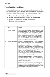
... paper jam problems, continue with the service check. If the paper feed motor turns in two directions. Remove the paper feed motor and check the shaft for loose or worn motor gear. 2-8 Service Manual If you begin the service check: • Check the entire paper path for obstructions. • Be sure there is not too much paper in the sheet feeder. • Be sure the correct type of -form sensor lever is being used. • Check...
... paper jam problems, continue with the service check. If the paper feed motor turns in two directions. Remove the paper feed motor and check the shaft for loose or worn motor gear. 2-8 Service Manual If you begin the service check: • Check the entire paper path for obstructions. • Be sure there is not too much paper in the sheet feeder. • Be sure the correct type of -form sensor lever is being used. • Check...
Service Manual
Page 22
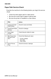
... Paper Path Service Check Examine the machine for the following for damage. Springs 3 Auto Sheet Feeder Check the pick rollers for wear. 4 Mid-Frame Asm Access Cover Asm Check the following before you begin this service check: • Check the entire paper path for obstructions. • Be sure the correct type of -Forms Flag Check for binds or damage. 2-10 Service Manual FRU Action 1 Large and Small Feed Rollers Check...
... Paper Path Service Check Examine the machine for the following for damage. Springs 3 Auto Sheet Feeder Check the pick rollers for wear. 4 Mid-Frame Asm Access Cover Asm Check the following before you begin this service check: • Check the entire paper path for obstructions. • Be sure the correct type of -Forms Flag Check for binds or damage. 2-10 Service Manual FRU Action 1 Large and Small Feed Rollers Check...

Service Manual
Page 24
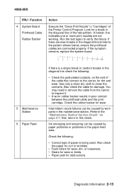
4096-00X Print Quality Service Check FRU / Function 1 Print Cartridge 2 Color Print Cartridge Cross Contamination 3 Printhead Carrier Assembly Action Be sure the machine contains a good print cartridge. Reseat the printhead cables in the system board and check the following parts for yellow, (when yellow and blue are mixed in incorrect colors printed, as the print cartridge is used. This problem resolves quickly as when green prints for wear or damage: • Print Cartridge Latch • Latch Spring...
4096-00X Print Quality Service Check FRU / Function 1 Print Cartridge 2 Color Print Cartridge Cross Contamination 3 Printhead Carrier Assembly Action Be sure the machine contains a good print cartridge. Reseat the printhead cables in the system board and check the following parts for yellow, (when yellow and blue are mixed in incorrect colors printed, as the print cartridge is used. This problem resolves quickly as when green prints for wear or damage: • Print Cartridge Latch • Latch Spring...
Service Manual
Page 25
... line of the test pattern. A broken line indicates one or more print nozzles are connected properly. Check the following : • Check the gold-plated contacts, on page 2-7, then return to this check. Also check the cable for obstructions. If the symptom remains, replace the system board. 5 Maintenance Station 6 Paper Feed If there is a single break or random breaks in the diagonal line check the following : • Correct type of paper is being used...
... line of the test pattern. A broken line indicates one or more print nozzles are connected properly. Check the following : • Check the gold-plated contacts, on page 2-7, then return to this check. Also check the cable for obstructions. If the symptom remains, replace the system board. 5 Maintenance Station 6 Paper Feed If there is a single break or random breaks in the diagonal line check the following : • Correct type of paper is being used...
Service Manual
Page 26
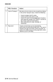
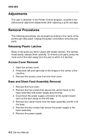
... the bidirectional printing alignment, when replacing a print cartridge. 2-14 Service Manual The user is directed, through the Printer Control program, to carrier frame engagement should be lubricated with grease P/N 1329301, as well as the carrier guide rod and bearing. • Idler pulley parts for wear, damage, or looseness. 4096-00X FRU / Function 7 Carrier Transport 8 Alignment Action Blurred print and voids can be adjusted by problems in...
... the bidirectional printing alignment, when replacing a print cartridge. 2-14 Service Manual The user is directed, through the Printer Control program, to carrier frame engagement should be lubricated with grease P/N 1329301, as well as the carrier guide rod and bearing. • Idler pulley parts for wear, damage, or looseness. 4096-00X FRU / Function 7 Carrier Transport 8 Alignment Action Blurred print and voids can be adjusted by problems in...

Service Manual
Page 29
... the following before removing logic boards: • Keep the ESD-sensitive part in its special bag. • Machine covers and metal tables are not working with your body to prevent an increase of damage because they make adjustments to the printer and how to the system ground point. if you are ready to install the part into its original shipping...
... the following before removing logic boards: • Keep the ESD-sensitive part in its special bag. • Machine covers and metal tables are not working with your body to prevent an increase of damage because they make adjustments to the printer and how to the system ground point. if you are ready to install the part into its original shipping...
Service Manual
Page 30
... carefully. Access Cover Removal 1. Unplug the power cord before removing any parts. Open the access cover. 2. Press both left side. 4. Remove the power supply. 4-2 Service Manual The latches break easily; Remove the five screws that secure the power supply to which it off the base. 5. 4096-00X Adjustments The user is latched. Remove the carrier frame from the base assembly and lift it is directed, in place with plastic latches. Removal Procedures The...
... carefully. Access Cover Removal 1. Unplug the power cord before removing any parts. Open the access cover. 2. Press both left side. 4. Remove the power supply. 4-2 Service Manual The latches break easily; Remove the five screws that secure the power supply to which it off the base. 5. 4096-00X Adjustments The user is latched. Remove the carrier frame from the base assembly and lift it is directed, in place with plastic latches. Removal Procedures The...

Service Manual
Page 32
... connector from the system board. 4. End-of the drive train assembly. 4096-00X Drive Train Assembly Removal 1. Remove the front cover. 2. Remove the large feed roll and mid-frame assembly. 7. Note: The paper feed motor is a part of -Form Flag Removal 1. Disconnect all cables from the system board. 8. Remove the carrier frame. 3. Remove the maintenance station assembly. 5. Remove the four screws securing the system board to the...
... connector from the system board. 4. End-of the drive train assembly. 4096-00X Drive Train Assembly Removal 1. Remove the front cover. 2. Remove the large feed roll and mid-frame assembly. 7. Note: The paper feed motor is a part of -Form Flag Removal 1. Disconnect all cables from the system board. 8. Remove the carrier frame. 3. Remove the maintenance station assembly. 5. Remove the four screws securing the system board to the...

Service Manual
Page 34
... the power supply connector from the base assembly. 3. Power Supply Removal 1. Disconnect the printhead cable from the base assembly. 3. Lift the carrier out of the machine. 5. Remove the carrier frame from the system board. 3. Remove the front cover. 2. Printhead Carrier Assembly Removal 1. Remove each of the small feed roll assemblies from the right end of the carrier guide rod. 4. Remove the retainer spring from the frame. 4-6 Service Manual Remove the...
... the power supply connector from the base assembly. 3. Power Supply Removal 1. Disconnect the printhead cable from the base assembly. 3. Lift the carrier out of the machine. 5. Remove the carrier frame from the system board. 3. Remove the front cover. 2. Printhead Carrier Assembly Removal 1. Remove each of the small feed roll assemblies from the right end of the carrier guide rod. 4. Remove the retainer spring from the frame. 4-6 Service Manual Remove the...

Service Manual
Page 53
...1-1 Problems Carrier Transport 2-2 Maintenance Station 2-2 Paper Feed 2-3 Paper Feed Button 2-2 Power 2-3 Print Quality 2-3 R Removals Access Cover 4-2 Base Assembly 4-2 Carrier Belt Asm 4-3 Carrier Frame Asm 4-3 Carrier Transport Motor 4-3 Drive Train Assembly 4-4 End-of-Form Flag 4-4 Front Cover 4-5 Large Feed Roll 4-5 Maintenance Station 4-5 Mid-Frame Assembly 4-6 Power Supply 4-6 Printhead Carrier Asm 4-6 Sheet Feed Asm 4-2 Small Feed Roll Asm 4-6 System Board 4-7 S Safety Information v Service Checks Envelope Feed 2-6 Maintenance Station 2-6 Paper Feed 2-8 Paper Path 2-9 Power 2-10 Print...
...1-1 Problems Carrier Transport 2-2 Maintenance Station 2-2 Paper Feed 2-3 Paper Feed Button 2-2 Power 2-3 Print Quality 2-3 R Removals Access Cover 4-2 Base Assembly 4-2 Carrier Belt Asm 4-3 Carrier Frame Asm 4-3 Carrier Transport Motor 4-3 Drive Train Assembly 4-4 End-of-Form Flag 4-4 Front Cover 4-5 Large Feed Roll 4-5 Maintenance Station 4-5 Mid-Frame Assembly 4-6 Power Supply 4-6 Printhead Carrier Asm 4-6 Sheet Feed Asm 4-2 Small Feed Roll Asm 4-6 System Board 4-7 S Safety Information v Service Checks Envelope Feed 2-6 Maintenance Station 2-6 Paper Feed 2-8 Paper Path 2-9 Power 2-10 Print...


