Hardware Maintenance Manual
Page 5
...General Checkout . . . . . 31 Problem determination tips 31 Chapter 5. Symptom-to non-RAID 42 Chapter 8. Diagnostics 33 Lenovo ThinkVantage Toolbox 33 Lenovo Solution Center 33 PC-Doctor for DOS 34 Creating a diagnostic disc 34 Running the diagnostic program from the diagnostic disc 34 ...module . . . . 77 Replacing the battery 79 Installing or replacing the optical drive . . . . . 80 Replacing the card reader 82 Replacing the power supply assembly . . . . . 84 Replacing the heat sink and fan assembly . . . . 86 Replacing the microprocessor 88 Replacing the system board 91 ...
...General Checkout . . . . . 31 Problem determination tips 31 Chapter 5. Symptom-to non-RAID 42 Chapter 8. Diagnostics 33 Lenovo ThinkVantage Toolbox 33 Lenovo Solution Center 33 PC-Doctor for DOS 34 Creating a diagnostic disc 34 Running the diagnostic program from the diagnostic disc 34 ...module . . . . 77 Replacing the battery 79 Installing or replacing the optical drive . . . . . 80 Replacing the card reader 82 Replacing the power supply assembly . . . . . 84 Replacing the heat sink and fan assembly . . . . 86 Replacing the microprocessor 88 Replacing the system board 91 ...

Hardware Maintenance Manual
Page 10
... you start to decrease electrostatic discharges. such touching can then operate the switch or unplug the power cord quickly. • Do not work area. Power supply units - Motor generators and similar units. (This practice ensures correct grounding of maintenance information. ...frames. Blowers and fans - Some hand tools have , near power supplies - Many customers have handles covered with powered-on suitable rubber mats (obtained locally, if necessary) to get medical aid. 4 ThinkStation Hardware Maintenance Manual When using a tester, set the controls ...
... you start to decrease electrostatic discharges. such touching can then operate the switch or unplug the power cord quickly. • Do not work area. Power supply units - Motor generators and similar units. (This practice ensures correct grounding of maintenance information. ...frames. Blowers and fans - Some hand tools have , near power supplies - Many customers have handles covered with powered-on suitable rubber mats (obtained locally, if necessary) to get medical aid. 4 ThinkStation Hardware Maintenance Manual When using a tester, set the controls ...

Hardware Maintenance Manual
Page 11
...cables. 8. Use product-specific ESD procedures when they exceed the requirements noted here. 2. Begin the checks with the power off the computer. Check that the power-supply cover fasteners (screws or rivets) have been certified (ISO 9000) as specified in charge between the external ground ...to assist you in identifying potentially unsafe conditions on these conditions and the safety hazards they present: • Electrical hazards, especially primary power (primary voltage on the frame can cause serious or fatal electrical shock). • Explosive hazards, such as a damaged CRT face...
...cables. 8. Use product-specific ESD procedures when they exceed the requirements noted here. 2. Begin the checks with the power off the computer. Check that the power-supply cover fasteners (screws or rivets) have been certified (ISO 9000) as specified in charge between the external ground ...to assist you in identifying potentially unsafe conditions on these conditions and the safety hazards they present: • Electrical hazards, especially primary power (primary voltage on the frame can cause serious or fatal electrical shock). • Explosive hazards, such as a damaged CRT face...
Hardware Maintenance Manual
Page 14
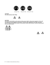
To remove all electrical current from the device, ensure that all power cords are disconnected from the power source. 2 1 8 ThinkStation Hardware Maintenance Manual ≥18 kg (37 lbs) ≥32 kg (70.5 lbs) ≥55 kg (121.2 lbs) CAUTION: Use safe practices when lifting. CAUTION: The power control button on the device and the power switch on the power supply do not turn off the electrical current supplied to the device. The device also might have more than one power cord.
To remove all electrical current from the device, ensure that all power cords are disconnected from the power source. 2 1 8 ThinkStation Hardware Maintenance Manual ≥18 kg (37 lbs) ≥32 kg (70.5 lbs) ≥55 kg (121.2 lbs) CAUTION: Use safe practices when lifting. CAUTION: The power control button on the device and the power switch on the power supply do not turn off the electrical current supplied to the device. The device also might have more than one power cord.
Hardware Maintenance Manual
Page 49
...the following procedures. FRU/Action Reseat connectors Power cord Turn on the failing hard disk drive. 2. Symptom-to-FRU Index The Symptom-to "Undetermined problems" on the start -up the data on switch © Copyright Lenovo 2011, 2012 43 If you decide which...first. • If you suspect a power problem, use the following for proper installation. • Power cord • On/Off switch connector • On/Off switch power supply connector • System board power supply connectors • Microprocessor(s) connection Check the power cord for continuity. The drive must be ...
...the following procedures. FRU/Action Reseat connectors Power cord Turn on the failing hard disk drive. 2. Symptom-to-FRU Index The Symptom-to "Undetermined problems" on the start -up the data on switch © Copyright Lenovo 2011, 2012 43 If you decide which...first. • If you suspect a power problem, use the following for proper installation. • Power cord • On/Off switch connector • On/Off switch power supply connector • System board power supply connectors • Microprocessor(s) connection Check the power cord for continuity. The drive must be ...
Hardware Maintenance Manual
Page 59
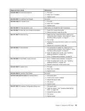
... function test. 1. PCI card 2. Flash the system. Reseat IDE signal cable. 4. Go to "Undetermined problems" on page 169. 3. Replace component under test. 1. PCI card 2. Check power supply voltages. 3. If a component is called out is connected and/or enabled. Go to reset the log file. 1. See Chapter 6 "Using the Setup Utility program" on...
... function test. 1. PCI card 2. Flash the system. Reseat IDE signal cable. 4. Go to "Undetermined problems" on page 169. 3. Replace component under test. 1. PCI card 2. Check power supply voltages. 3. If a component is called out is connected and/or enabled. Go to reset the log file. 1. See Chapter 6 "Using the Setup Utility program" on...
Hardware Maintenance Manual
Page 60
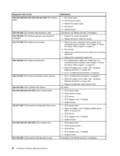
...the BIOS" on page 65. 2. System board 1. SCSI device 4. System board Information only Restart the test, if necessary. 54 ThinkStation Hardware Maintenance Manual IDE signal cable 2. Make sure the component that is called out is connected and/or enabled. See "Updating (flashing...under function test. See "Updating (flashing) the BIOS" on page 169. 3. Check power supply 3. Reseat IDE signal cable. 4. Replace component under test. 1. System board 1. SCSI device 4. SCSI signal cable 2. Check power supply. 3. See Chapter 6 "Using the Setup Utility program" on page 37. 2. ...
...the BIOS" on page 65. 2. System board 1. SCSI device 4. System board Information only Restart the test, if necessary. 54 ThinkStation Hardware Maintenance Manual IDE signal cable 2. Make sure the component that is called out is connected and/or enabled. See "Updating (flashing...under function test. See "Updating (flashing) the BIOS" on page 169. 3. Check power supply 3. Reseat IDE signal cable. 4. Replace component under test. 1. System board 1. SCSI device 4. SCSI signal cable 2. Check power supply. 3. See Chapter 6 "Using the Setup Utility program" on page 37. 2. ...
Hardware Maintenance Manual
Page 65
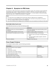
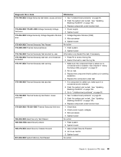
... Test Passed No action 175-0XX-XXX Thermal Sensor(s) failure 1. Re-run test. 3. Flash the system and re-test. Check power supply voltages. 3. System board 185-000-XXX Asset Security Test Passed No action 185-XXX-XXX Asset Security failure 1. Replace component under ...1. Replace the component that is called out in warning statement. 4. Assure Asset Security Enabled 2. Symptom-to review the log file. 2. Power supply 2. System board 175-195-XXX Thermal Sensor(s) Test aborted by user Information only Restart the test, if necessary. 175-196-XXX Thermal ...
... Test Passed No action 175-0XX-XXX Thermal Sensor(s) failure 1. Re-run test. 3. Flash the system and re-test. Check power supply voltages. 3. System board 185-000-XXX Asset Security Test Passed No action 185-XXX-XXX Asset Security failure 1. Replace component under ...1. Replace the component that is called out in warning statement. 4. Assure Asset Security Enabled 2. Symptom-to review the log file. 2. Power supply 2. System board 175-195-XXX Thermal Sensor(s) Test aborted by user Information only Restart the test, if necessary. 175-196-XXX Thermal ...
Hardware Maintenance Manual
Page 66
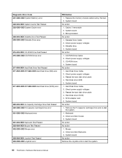
...Capacity Cartridge Drive and re-test the system. 1. Mouse 2. Check power supply voltages 3. System board 1. Reseat the hard disk drive cable 4. Keyboard 2. System board No action 1. Diskette Drive Cable 2. Check power supply voltages 3. Reseat the hard disk drive cable 4. Cache, if removable...SCSI adapter card 6. Check and test Keyboard. 3. Hard Disk Drive Cable 2. Check power supply voltages 3. System board No action Remove the Joystick and re-test the system. 60 ThinkStation Hardware Maintenance Manual System board No action No action 1. Diskette drive 4. CD-ROM ...
...Capacity Cartridge Drive and re-test the system. 1. Mouse 2. Check power supply voltages 3. System board 1. Reseat the hard disk drive cable 4. Keyboard 2. System board No action 1. Diskette Drive Cable 2. Check power supply voltages 3. Reseat the hard disk drive cable 4. Cache, if removable...SCSI adapter card 6. Check and test Keyboard. 3. Hard Disk Drive Cable 2. Check power supply voltages 3. System board No action Remove the Joystick and re-test the system. 60 ThinkStation Hardware Maintenance Manual System board No action No action 1. Diskette drive 4. CD-ROM ...
Hardware Maintenance Manual
Page 69
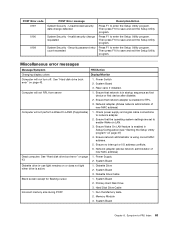
.... 2. Miscellaneous error messages Message/Symptom FRU/Action Changing display colors Display/Monitor Computer will not RPL from server 1. Check power supply and signal cable connections to save and exit the Setup Utility program. Network adapter (advise network administrator of new MAC address...63 Ensure that network is using correct MAC address. 5. Network adapter (Advise network administrator of new MAC address) Dead computer. Power Supply 2. System Board 2. Hard Disk Drive Cable Incorrect memory size during POST 1. Then press F10 to enter the Setup Utility ...
.... 2. Miscellaneous error messages Message/Symptom FRU/Action Changing display colors Display/Monitor Computer will not RPL from server 1. Check power supply and signal cable connections to save and exit the Setup Utility program. Network adapter (advise network administrator of new MAC address...63 Ensure that network is using correct MAC address. 5. Network adapter (Advise network administrator of new MAC address) Dead computer. Power Supply 2. System Board 2. Hard Disk Drive Cable Incorrect memory size during POST 1. Then press F10 to enter the Setup Utility ...
Hardware Maintenance Manual
Page 70
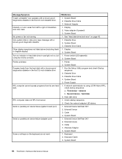
...disk 2. Serial or parallel port device failure (system board port) 1. External Device Self-Test OK? 2. Keyboard 2. System Board 64 ThinkStation Hardware Maintenance Manual Display 2. System Board 3. Display 2. Second device - System Board 2. System Board Turn on indicator or hard disk drive... or disk error-type message with a known-good diagnostics diskette in the first 3.5-inch diskette drive 1. Diskette Drive 2. Power Supply RPL computer cannot access programs from server 1. Check the network adapter LED status. Run the Setup Utility program and check Startup...
...disk 2. Serial or parallel port device failure (system board port) 1. External Device Self-Test OK? 2. Keyboard 2. System Board 64 ThinkStation Hardware Maintenance Manual Display 2. System Board 3. Display 2. Second device - System Board 2. System Board Turn on indicator or hard disk drive... or disk error-type message with a known-good diagnostics diskette in the first 3.5-inch diskette drive 1. Diskette Drive 2. Power Supply RPL computer cannot access programs from server 1. Check the network adapter LED status. Run the Setup Utility program and check Startup...
Hardware Maintenance Manual
Page 76
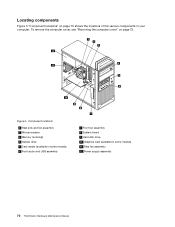
Locating components Figure 3 "Component locations" on page 72. Figure 3. To remove the computer cover, see "Removing the computer cover" on page 70 shows the locations of the various components in some models) 11 Rear fan assembly 12 Power supply assembly 70 ThinkStation Hardware Maintenance Manual Component locations 1 Heat sink and fan assembly 2 Microprocessor 3 Memory module(s) 4 Optical drive 5 Card reader (available in some models) 6 Front audio and USB assembly 7 Front fan assembly 8 System board 9 Hard disk drive 10 Graphics card (available in your computer.
Locating components Figure 3 "Component locations" on page 72. Figure 3. To remove the computer cover, see "Removing the computer cover" on page 70 shows the locations of the various components in some models) 11 Rear fan assembly 12 Power supply assembly 70 ThinkStation Hardware Maintenance Manual Component locations 1 Heat sink and fan assembly 2 Microprocessor 3 Memory module(s) 4 Optical drive 5 Card reader (available in some models) 6 Front audio and USB assembly 7 Front fan assembly 8 System board 9 Hard disk drive 10 Graphics card (available in your computer.
Hardware Maintenance Manual
Page 90
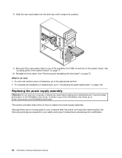
... the power supply assembly. Replacing the power supply assembly Attention: Do not open your computer or attempt any repair before reading and understanding the "Important safety information" in your computer after the power cord has been disconnected, the following warnings are required for your safety and proper Underwriters Laboratories (UL) certification. 84 ThinkStation Hardware ...new card reader into the drive bay until it snaps into position. 9. 8. What to do next: • To work with another piece of the ThinkStation User Guide, go to : http://www.lenovo.com/ThinkStationUserGuides.
... the power supply assembly. Replacing the power supply assembly Attention: Do not open your computer or attempt any repair before reading and understanding the "Important safety information" in your computer after the power cord has been disconnected, the following warnings are required for your safety and proper Underwriters Laboratories (UL) certification. 84 ThinkStation Hardware ...new card reader into the drive bay until it snaps into position. 9. 8. What to do next: • To work with another piece of the ThinkStation User Guide, go to : http://www.lenovo.com/ThinkStationUserGuides.
Hardware Maintenance Manual
Page 91
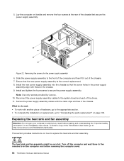
... on the system board" on page 72. 3. To replace the power supply assembly, do the following label attached. Remove the computer cover. Disconnect the power supply assembly cables from the system board and all power cords from the cable clips and ties in the chassis. Chapter 9.... DANGER Hazardous moving parts. CAUTION: Never remove the cover on a power supply or any component that has the following : 1. Release the power supply assembly cables from electrical outlets. 2. If you suspect a problem with one of these components. Hazardous voltage...
... on the system board" on page 72. 3. To replace the power supply assembly, do the following label attached. Remove the computer cover. Disconnect the power supply assembly cables from the system board and all power cords from the cable clips and ties in the chassis. Chapter 9.... DANGER Hazardous moving parts. CAUTION: Never remove the cover on a power supply or any component that has the following : 1. Release the power supply assembly cables from electrical outlets. 2. If you suspect a problem with one of these components. Hazardous voltage...
Hardware Maintenance Manual
Page 92
... the heat sink and fan assembly. Install the new power supply assembly into the chassis so that the screw holes in the power supply assembly align with the cable clips and ties in the ThinkStation User Guide. Turn off the computer and wait three to...://www.lenovo.com/ThinkStationUserGuides. Removing the screws for the power supply assembly 6. Reconnect the power supply assembly cables to secure the power supply assembly. Replacing the heat sink and fan assembly Attention: Do not open your computer or attempt any repair before removing the computer cover. 86 ThinkStation Hardware...
... the heat sink and fan assembly. Install the new power supply assembly into the chassis so that the screw holes in the power supply assembly align with the cable clips and ties in the ThinkStation User Guide. Turn off the computer and wait three to...://www.lenovo.com/ThinkStationUserGuides. Removing the screws for the power supply assembly 6. Reconnect the power supply assembly cables to secure the power supply assembly. Replacing the heat sink and fan assembly Attention: Do not open your computer or attempt any repair before removing the computer cover. 86 ThinkStation Hardware...
Hardware Maintenance Manual
Page 121
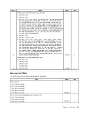
... models • MT 7783: all models • MT 7821: all models FRU # CRU 03W5421 1 45K2301 2 Chapter 10. FRU lists 115 Item # 12 12 FRUs Power supply, 280 Watt power supply (85 plus) • MT 7782: CTO • MT 7783: CTO • MT 7783: CTO 11J 12J 13J 14J 15J 16M 17M 19M 21M 22M... B7C B8J B9J C1J C2G C3G C4U C4F B9J C1J C5M C6M C7M C8G C9G D1G D2G D3M D4M D5G D6G D7G D8G D9J Power supply, 320 Watt power supply (90%) • MT 7782: CTO • MT 7783: CTO • MT 7821: CTO • MT 7823: CTO • MT 7824: CTO FRU # 45J9431 54Y8841...
... models • MT 7783: all models • MT 7821: all models FRU # CRU 03W5421 1 45K2301 2 Chapter 10. FRU lists 115 Item # 12 12 FRUs Power supply, 280 Watt power supply (85 plus) • MT 7782: CTO • MT 7783: CTO • MT 7783: CTO 11J 12J 13J 14J 15J 16M 17M 19M 21M 22M... B7C B8J B9J C1J C2G C3G C4U C4F B9J C1J C5M C6M C7M C8G C9G D1G D2G D3M D4M D5G D6G D7G D8G D9J Power supply, 320 Watt power supply (90%) • MT 7782: CTO • MT 7783: CTO • MT 7821: CTO • MT 7823: CTO • MT 7824: CTO FRU # 45J9431 54Y8841...
Hardware Maintenance Manual
Page 177
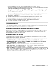
...The recovery session begins. During this capability to restart the operating system. Remove the disc from another computer on automatically. Automatic configuration and power interface (ACPI) BIOS Being an ACPI BIOS system, the operating system is detected on the internal modem. • PCI Wake Up: ... for the computer and monitor to electrical outlets. Move the Clear CMOS /Recovery jumper back to control the power management features of the computer such as the system power supply, processor, hard disk drives, and some monitors. 6. Turn on the computer to wake the system. •...
...The recovery session begins. During this capability to restart the operating system. Remove the disc from another computer on automatically. Automatic configuration and power interface (ACPI) BIOS Being an ACPI BIOS system, the operating system is detected on the internal modem. • PCI Wake Up: ... for the computer and monitor to electrical outlets. Move the Clear CMOS /Recovery jumper back to control the power management features of the computer such as the system power supply, processor, hard disk drives, and some monitors. 6. Turn on the computer to wake the system. •...
Hardware Maintenance Manual
Page 181
...sink and fan assembly, replacing 86 I installing options memory module 77 PCI card 74 K keyboard connector 69 L Lenovo Solution Center 33 Lenovo ThinkVantage Toolbox 33 locating components 70 M memory module installing, replacing 77 system board 77 Microphone connector 69 microprocessor replacing ... replacement, completing 102 password Administrator 38 considerations 38 Power-On Password 38 setting, changing, deleting 38 passwords, using 37 PCI card 74 installing, replacing 74 slots 74 physical specifications 30 power supply assembly, replacing 84 Power-On, Password 38 R rear connectors 68 rear ...
...sink and fan assembly, replacing 86 I installing options memory module 77 PCI card 74 K keyboard connector 69 L Lenovo Solution Center 33 Lenovo ThinkVantage Toolbox 33 locating components 70 M memory module installing, replacing 77 system board 77 Microphone connector 69 microprocessor replacing ... replacement, completing 102 password Administrator 38 considerations 38 Power-On Password 38 setting, changing, deleting 38 passwords, using 37 PCI card 74 installing, replacing 74 slots 74 physical specifications 30 power supply assembly, replacing 84 Power-On, Password 38 R rear connectors 68 rear ...
(English) User Guide
Page 3
...12 Chapter 2. Using the Setup Utility program 59 i Product overview 1 Features 1 Specifications 4 Software overview 5 Software provided by Lenovo 5 Adobe Reader 6 Antivirus software 6 Locations 6 Locating connectors, controls, and indicators on the front of your computer to ...and outlets v External devices v Heat and product ventilation v Operating environment vi Modem safety information vi Laser compliance statement vii Power supply statement vii Cleaning and maintenance vii Chapter 1. Contents Important safety information . . . . . Installing or replacing hardware 25...
...12 Chapter 2. Using the Setup Utility program 59 i Product overview 1 Features 1 Specifications 4 Software overview 5 Software provided by Lenovo 5 Adobe Reader 6 Antivirus software 6 Locations 6 Locating connectors, controls, and indicators on the front of your computer to ...and outlets v External devices v Heat and product ventilation v Operating environment vi Modem safety information vi Laser compliance statement vii Power supply statement vii Cleaning and maintenance vii Chapter 1. Contents Important safety information . . . . . Installing or replacing hardware 25...
(English) User Guide
Page 6
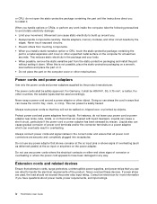
... electrical contacts on the computer cover or other countries, the suitable types shall be safety approved. iv ThinkStation User Guide When you . • Always handle components carefully. Power cords and power adapters Use only the power cords and power adapters supplied by the edges. For other metal surface. This can cause a short circuit, particularly if the...
... electrical contacts on the computer cover or other countries, the suitable types shall be safety approved. iv ThinkStation User Guide When you . • Always handle components carefully. Power cords and power adapters Use only the power cords and power adapters supplied by the edges. For other metal surface. This can cause a short circuit, particularly if the...


