
Instructions for Enabling EuP Mode in Setup Utility
Page 1
... Enter. 6. Press Enter when prompted to enable EuP (Energy using Products) mode in the Setup Utility program for ThinkStation™ computer machine types 4105, 4155, 4157, 4158, 4217, and 4218. To enable EuP mode in Contract No. From the Setup Utility program main menu, select ... off . Make sure your computer is enabled, you cannot perform the following : 1. When you type the correct password. 3. Lenovo, the Lenovo logo, and ThinkStation are sold to governmental entities as commercial items as defined by 48 C.F.R. 2.101 with limited and restricted rights to use , reproduction...
... Enter. 6. Press Enter when prompted to enable EuP (Energy using Products) mode in the Setup Utility program for ThinkStation™ computer machine types 4105, 4155, 4157, 4158, 4217, and 4218. To enable EuP mode in Contract No. From the Setup Utility program main menu, select ... off . Make sure your computer is enabled, you cannot perform the following : 1. When you type the correct password. 3. Lenovo, the Lenovo logo, and ThinkStation are sold to governmental entities as commercial items as defined by 48 C.F.R. 2.101 with limited and restricted rights to use , reproduction...

Hardware Maintenance Manual
Page 1
ThinkStation Hardware Maintenance Manual Machine Type: 4105, 4155, 4157, 4158, 4217, 4218
ThinkStation Hardware Maintenance Manual Machine Type: 4105, 4155, 4157, 4158, 4217, 4218
Hardware Maintenance Manual
Page 3
ThinkStation Hardware Maintenance Manual Machine Type: 4105, 4155, 4157, 4158, 4217, 4218
ThinkStation Hardware Maintenance Manual Machine Type: 4105, 4155, 4157, 4158, 4217, 4218
Hardware Maintenance Manual
Page 5
... . 36 Running diagnostics from the Setup Utility program . . . . . 44 Chapter 7. Installing hard disk drives and configuring RAID (types: 4155, 4158, 4218 49 Installing SATA or SAS hard disk drives and configuring RAID 49 Installing SATA or SAS hard disk drives . . . 49 Entering the Marvell ... optional hot spare hard disk drive . . . . 48 Configuring the Marvell BIOS Setup to delete an array 50 © Copyright Lenovo 2008, 2012 iii Safety information 3 General safety 3 Electrical safety 3 Voltage-selection switch 5 Safety inspection guide 5 Handling electrostatic discharge-sensitive...
... . 36 Running diagnostics from the Setup Utility program . . . . . 44 Chapter 7. Installing hard disk drives and configuring RAID (types: 4155, 4158, 4218 49 Installing SATA or SAS hard disk drives and configuring RAID 49 Installing SATA or SAS hard disk drives . . . 49 Entering the Marvell ... optional hot spare hard disk drive . . . . 48 Configuring the Marvell BIOS Setup to delete an array 50 © Copyright Lenovo 2008, 2012 iii Safety information 3 General safety 3 Electrical safety 3 Voltage-selection switch 5 Safety inspection guide 5 Handling electrostatic discharge-sensitive...

Hardware Maintenance Manual
Page 6
...54 Beep symptoms 71 POST error codes 72 Miscellaneous error messages 73 Undetermined problems 75 Chapter 10. Replacing FRUs (Type 4155, 4158, 4218 109 Locating controls and connectors on the front of your computer 109 Rear connectors 109 Removing the cover 110 Locations ... PCI adapter card 118 Replacing the heat sink 121 Replacing the microprocessor 122 Replacing the system board 124 Replacing a hard disk drive 127 iv ThinkStation Hardware Maintenance Manual Replacing the hard disk drive fan assembly . . . 130 Replacing an optical drive 131 Replacing the diskette drive or card ...
...54 Beep symptoms 71 POST error codes 72 Miscellaneous error messages 73 Undetermined problems 75 Chapter 10. Replacing FRUs (Type 4155, 4158, 4218 109 Locating controls and connectors on the front of your computer 109 Rear connectors 109 Removing the cover 110 Locations ... PCI adapter card 118 Replacing the heat sink 121 Replacing the microprocessor 122 Replacing the system board 124 Replacing a hard disk drive 127 iv ThinkStation Hardware Maintenance Manual Replacing the hard disk drive fan assembly . . . 130 Replacing an optical drive 131 Replacing the diskette drive or card ...

Hardware Maintenance Manual
Page 38
...4157, and 4217. Input kilovolt-amperes (kVA) (approximate) Minimum configuration as shipped: 0.17 kVA Maximum configuration: 0.8 kVA For machine types 4155, 4158, and 4218. This section lists the physical specifications for your computer. Range 100 V - 240 V - Dimensions Width: 210 mm (8.3 inches) ... lbs) Rack mounted dimensions: Width: 427 mm (16.8 inches) Height: 210 mm (8.3 inches) Depth: 602 mm (23.7 inches) Environment 30 ThinkStation Hardware Maintenance Manual Dimensions Width: 175 mm (6.9 inches) Height: 478 mm (18.8 inches) floor to 90% • Maximum altitude: 7000 ft ...
...4157, and 4217. Input kilovolt-amperes (kVA) (approximate) Minimum configuration as shipped: 0.17 kVA Maximum configuration: 0.8 kVA For machine types 4155, 4158, and 4218. This section lists the physical specifications for your computer. Range 100 V - 240 V - Dimensions Width: 210 mm (8.3 inches) ... lbs) Rack mounted dimensions: Width: 427 mm (16.8 inches) Height: 210 mm (8.3 inches) Depth: 602 mm (23.7 inches) Environment 30 ThinkStation Hardware Maintenance Manual Dimensions Width: 175 mm (6.9 inches) Height: 478 mm (18.8 inches) floor to 90% • Maximum altitude: 7000 ft ...
Hardware Maintenance Manual
Page 57
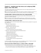
...how to enter the Marvell BIOS Setup to configure SATA/SAS RAID. © Copyright Lenovo 2008, 2012 49 Press Ctrl+M when prompted to enter the Marvell BIOS Setup to configure...a SATA or SAS RAID. 1. Installing hard disk drives and configuring RAID (types: 4155, 4158, 4218) This chapter contains information about the required number of SATA or SAS hard disk drives...a Linux environment, contact your Linux software provider. For information about configuring RAID in the ThinkStation Hardware Installation and Replacement Guide. However, be sure that you have the minimum number of...
...how to enter the Marvell BIOS Setup to configure SATA/SAS RAID. © Copyright Lenovo 2008, 2012 49 Press Ctrl+M when prompted to enter the Marvell BIOS Setup to configure...a SATA or SAS RAID. 1. Installing hard disk drives and configuring RAID (types: 4155, 4158, 4218) This chapter contains information about the required number of SATA or SAS hard disk drives...a Linux environment, contact your Linux software provider. For information about configuring RAID in the ThinkStation Hardware Installation and Replacement Guide. However, be sure that you have the minimum number of...

Hardware Maintenance Manual
Page 59
Press Y when prompted to select Next and press Enter. 6. From the RAID Config menu, select Delete array. 4. Chapter 8. The RAID Config menu opens. 3. Use the arrow keys to complete the deletion. Use the arrow keys and the Enter key to select the array you want to select RAID Config and press Enter. Installing hard disk drives and configuring RAID (types: 4155, 4158, 4218) 51 2. On the Marvell BIOS Setup screen, use the arrow keys to delete from the list. 5.
Press Y when prompted to select Next and press Enter. 6. From the RAID Config menu, select Delete array. 4. Chapter 8. The RAID Config menu opens. 3. Use the arrow keys to complete the deletion. Use the arrow keys and the Enter key to select the array you want to select RAID Config and press Enter. Installing hard disk drives and configuring RAID (types: 4155, 4158, 4218) 51 2. On the Marvell BIOS Setup screen, use the arrow keys to delete from the list. 5.

Hardware Maintenance Manual
Page 117
...on the front of your computer The following illustration shows the locations of the connectors on the rear of the computer. © Copyright Lenovo 2008, 2012 109 FRU replacements are documented. Note: Not all FRUs. Only the major FRUs are to be done by trained service... technicians only. Replacing FRUs (Type 4155, 4158, 4218) Important Before you work safely. Chapter 11. These precautions and guidelines will have the following controls and connections. 1 USB connector 2 Microphone...
...on the front of your computer The following illustration shows the locations of the connectors on the rear of the computer. © Copyright Lenovo 2008, 2012 109 FRU replacements are documented. Note: Not all FRUs. Only the major FRUs are to be done by trained service... technicians only. Replacing FRUs (Type 4155, 4158, 4218) Important Before you work safely. Chapter 11. These precautions and guidelines will have the following controls and connections. 1 USB connector 2 Microphone...

Hardware Maintenance Manual
Page 119
... locking devices, such as a cable lock or padlock that are connected to the computer. 3. Disconnect the cables attached to the computer. Replacing FRUs (Type 4155, 4158, 4218) 111 Chapter 11. Disengage the cover latch 1 and remove the cover.
... locking devices, such as a cable lock or padlock that are connected to the computer. 3. Disconnect the cables attached to the computer. Replacing FRUs (Type 4155, 4158, 4218) 111 Chapter 11. Disengage the cover latch 1 and remove the cover.
Hardware Maintenance Manual
Page 121
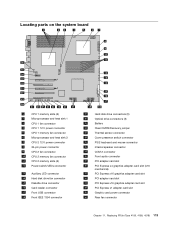
... adapter card slot 34 PCI Express x1 adapter card slot 35 Graphic card power connector 36 Rear fan connector Chapter 11. Replacing FRUs (Type 4155, 4158, 4218) 113
... adapter card slot 34 PCI Express x1 adapter card slot 35 Graphic card power connector 36 Rear fan connector Chapter 11. Replacing FRUs (Type 4155, 4158, 4218) 113

Hardware Maintenance Manual
Page 123
...supply. Note: For models that the new power supply is a voltage-selection switch, use a ballpoint pen to : http://www.lenovo.com/support. Replacing FRUs (Type 4155, 4158, 4218) 115 This section provides information about how to 230 V. 8. Remove the computer cover and then lay the computer on...the chassis. 6. Disconnect the power supply cables from all drives. 4. Remove the six power supply retaining screws at the rear of the ThinkStation Safety and Warranty Guide, go to slide the switch, if necessary. Some power supplies automatically sense the voltage, some power supplies are voltage ...
...supply. Note: For models that the new power supply is a voltage-selection switch, use a ballpoint pen to : http://www.lenovo.com/support. Replacing FRUs (Type 4155, 4158, 4218) 115 This section provides information about how to 230 V. 8. Remove the computer cover and then lay the computer on...the chassis. 6. Disconnect the power supply cables from all drives. 4. Remove the six power supply retaining screws at the rear of the ThinkStation Safety and Warranty Guide, go to slide the switch, if necessary. Some power supplies automatically sense the voltage, some power supplies are voltage ...

Hardware Maintenance Manual
Page 125
Open the retaining clips as shown. 6. Replacing FRUs (Type 4155, 4158, 4218) 117 5. Make sure the notch 1 on the memory module aligns correctly with the slot key 2 on the system board. Position the new memory module over the memory slot. Push the memory module straight down into the slot until the retaining clips close. If you are replacing an old memory module, open the retaining clips and remove the memory module being replaced as shown. Chapter 11.
Open the retaining clips as shown. 6. Replacing FRUs (Type 4155, 4158, 4218) 117 5. Make sure the notch 1 on the memory module aligns correctly with the slot key 2 on the system board. Position the new memory module over the memory slot. Push the memory module straight down into the slot until the retaining clips close. If you are replacing an old memory module, open the retaining clips and remove the memory module being replaced as shown. Chapter 11.

Hardware Maintenance Manual
Page 127
Note: The card is removed from the card slot. Replacing FRUs (Type 4155, 4158, 4218) 119 Disconnect all cable connections on page 113. 5. 3. Release the card support retaining latches. See "Locating parts on the system board " on the adapter ...
Note: The card is removed from the card slot. Replacing FRUs (Type 4155, 4158, 4218) 119 Disconnect all cable connections on page 113. 5. 3. Release the card support retaining latches. See "Locating parts on the system board " on the adapter ...

Hardware Maintenance Manual
Page 129
... , then fully remove screw 4 , and fully remove screw 3 . 5. Replacing FRUs (Type 4155, 4158, 4218) 121 Replacing the heat sink CAUTION: The heat sink and microprocessor might be very hot. This section...to let the computer cool before reading and understanding the "Important safety information" in the ThinkStation Safety and Warranty Guide that came with your computer or attempt any repair before opening ... FRU replacement" on page 108. To obtain a copy of the new heat sink to : http://www.lenovo.com/support. To replace the heat sink: 1. Lay the computer on how to install the card. ...
... , then fully remove screw 4 , and fully remove screw 3 . 5. Replacing FRUs (Type 4155, 4158, 4218) 121 Replacing the heat sink CAUTION: The heat sink and microprocessor might be very hot. This section...to let the computer cool before reading and understanding the "Important safety information" in the ThinkStation Safety and Warranty Guide that came with your computer or attempt any repair before opening ... FRU replacement" on page 108. To obtain a copy of the new heat sink to : http://www.lenovo.com/support. To replace the heat sink: 1. Lay the computer on how to install the card. ...

Hardware Maintenance Manual
Page 131
... microprocessor. Do not drop anything onto the microprocessor socket while it into the microprocessor socket of the notches 1 on the bottom. 5. Replacing FRUs (Type 4155, 4158, 4218) 123 Lower the microprocessor straight down into the socket. 7. Note the orientation of the system board. b. The socket pins must be kept as clean...
... microprocessor. Do not drop anything onto the microprocessor socket while it into the microprocessor socket of the notches 1 on the bottom. 5. Replacing FRUs (Type 4155, 4158, 4218) 123 Lower the microprocessor straight down into the socket. 7. Note the orientation of the system board. b. The socket pins must be kept as clean...

Hardware Maintenance Manual
Page 133
... must be performed on the microprocessor socket. Lower the socket cover straight down into the microprocessor socket on page 92. 12. Replacing FRUs (Type 4155, 4158, 4218) 125 To install the microprocessor socket cover: a. Align the notches 1 of the socket. Install the microprocessor socket cover removed from the new system board...
... must be performed on the microprocessor socket. Lower the socket cover straight down into the microprocessor socket on page 92. 12. Replacing FRUs (Type 4155, 4158, 4218) 125 To install the microprocessor socket cover: a. Align the notches 1 of the socket. Install the microprocessor socket cover removed from the new system board...

Hardware Maintenance Manual
Page 135
...and Warranty Guide, go to: http://www.lenovo.com/support. However, be sure that came with your ThinkStation User Guide. See "Locations" on page 78. 2. Pull the handle to the factory-installed state. Chapter 11. Replacing FRUs (Type 4155, 4158, 4218) 127 Attention: Your computer supports... obtain a copy of Product Recovery discs. This section provides instructions on recovering factory-installed software, refer to "Recovering software" in the ThinkStation Safety and Warranty Guide that you to replace the hard disk drive. Important When you receive a new hard disk drive, you also ...
...and Warranty Guide, go to: http://www.lenovo.com/support. However, be sure that came with your ThinkStation User Guide. See "Locations" on page 78. 2. Pull the handle to the factory-installed state. Chapter 11. Replacing FRUs (Type 4155, 4158, 4218) 127 Attention: Your computer supports... obtain a copy of Product Recovery discs. This section provides instructions on recovering factory-installed software, refer to "Recovering software" in the ThinkStation Safety and Warranty Guide that you to replace the hard disk drive. Important When you receive a new hard disk drive, you also ...

Hardware Maintenance Manual
Page 137
Replacing FRUs (Type 4155, 4158, 4218) 129 Figure 8. Connecting a 3.5-inch SAS hard disk drive 9. Chapter 11. Go to "Completing the FRU replacement" on page 108. Connecting a 2.5-inch SATA hard disk drive Figure 10. Connecting a 3.5-inch SATA hard disk drive Figure 9.
Replacing FRUs (Type 4155, 4158, 4218) 129 Figure 8. Connecting a 3.5-inch SAS hard disk drive 9. Chapter 11. Go to "Completing the FRU replacement" on page 108. Connecting a 2.5-inch SATA hard disk drive Figure 10. Connecting a 3.5-inch SATA hard disk drive Figure 9.

Hardware Maintenance Manual
Page 139
...Remove the computer cover. Remove the front bezel. Note the location of the optical drive. 5. Replacing FRUs (Type 4155, 4158, 4218) 131 To obtain a copy of the ThinkStation Safety and Warranty Guide, go to remove) and slide the optical drive from the rear of the optical drive cables. Press ...the drive latch 1 (for the drive you want to : http://www.lenovo.com/support. Chapter 11. 7. Connect the hard disk ...
...Remove the computer cover. Remove the front bezel. Note the location of the optical drive. 5. Replacing FRUs (Type 4155, 4158, 4218) 131 To obtain a copy of the ThinkStation Safety and Warranty Guide, go to remove) and slide the optical drive from the rear of the optical drive cables. Press ...the drive latch 1 (for the drive you want to : http://www.lenovo.com/support. Chapter 11. 7. Connect the hard disk ...