
Instructions for Enabling EuP Mode in Setup Utility
Page 1
...Waking the computer from any installed PCI (Peripheral Component Interconnect) card or PCI Express card, for ThinkStation™ computer machine types 4105, 4155, 4157, 4158, 4217, and 4218. LENOVO products, data, computer software, and services have been developed exclusively at private expense and are trademarks... hibernation mode or turned off . Enabling EuP mode helps to reduce the consumption of Lenovo in the United States, other countries, or both. Lenovo, the Lenovo logo, and ThinkStation are sold to governmental entities as commercial items as defined by 48 C.F.R. 2.101 with...
...Waking the computer from any installed PCI (Peripheral Component Interconnect) card or PCI Express card, for ThinkStation™ computer machine types 4105, 4155, 4157, 4158, 4217, and 4218. LENOVO products, data, computer software, and services have been developed exclusively at private expense and are trademarks... hibernation mode or turned off . Enabling EuP mode helps to reduce the consumption of Lenovo in the United States, other countries, or both. Lenovo, the Lenovo logo, and ThinkStation are sold to governmental entities as commercial items as defined by 48 C.F.R. 2.101 with...

Hardware Maintenance Manual
Page 1
ThinkStation Hardware Maintenance Manual Machine Type: 4105, 4155, 4157, 4158, 4217, 4218
ThinkStation Hardware Maintenance Manual Machine Type: 4105, 4155, 4157, 4158, 4217, 4218
Hardware Maintenance Manual
Page 3
ThinkStation Hardware Maintenance Manual Machine Type: 4105, 4155, 4157, 4158, 4217, 4218
ThinkStation Hardware Maintenance Manual Machine Type: 4105, 4155, 4157, 4158, 4217, 4218
Hardware Maintenance Manual
Page 5
... Grounding requirements 6 Safety notices (multi-lingual translations) . . . . . 6 Chapter 3. Installing hard disk drives and configuring RAID (types: 4155, 4158, 4218 49 Installing SATA or SAS hard disk drives and configuring RAID 49 Installing SATA or SAS hard disk drives . . . 49 ...Navigating through the diagnostics programs 37 Running tests 37 Viewing the test log 39 Chapter 6. General information . . . . 29 Lenovo Welcome Center 29 Lenovo Solution Center 29 SimpleTap 29 Additional information resources 29 Specifications 29 Chapter 4. General Checkout . . . . . 33 Problem ...
... Grounding requirements 6 Safety notices (multi-lingual translations) . . . . . 6 Chapter 3. Installing hard disk drives and configuring RAID (types: 4155, 4158, 4218 49 Installing SATA or SAS hard disk drives and configuring RAID 49 Installing SATA or SAS hard disk drives . . . 49 ...Navigating through the diagnostics programs 37 Running tests 37 Viewing the test log 39 Chapter 6. General information . . . . 29 Lenovo Welcome Center 29 Lenovo Solution Center 29 SimpleTap 29 Additional information resources 29 Specifications 29 Chapter 4. General Checkout . . . . . 33 Problem ...

Hardware Maintenance Manual
Page 6
...Recovery CD . . 186 Windows 7 Professional 64 SP1 Recovery CD 190 Windows 7 Ultimate 64 SP1 Recovery CD . . 194 Overall: MT 4155, 4158, and 4218 194 Mechanical FRUs 210 Keyboard and Mouse 212 Adapters and miscellaneous FRUs 230 Power Cords 234 Recovery discs 238 Windows XP ...PCI adapter card 118 Replacing the heat sink 121 Replacing the microprocessor 122 Replacing the system board 124 Replacing a hard disk drive 127 iv ThinkStation Hardware Maintenance Manual Replacing the hard disk drive fan assembly . . . 130 Replacing an optical drive 131 Replacing the diskette drive or card...
...Recovery CD . . 186 Windows 7 Professional 64 SP1 Recovery CD 190 Windows 7 Ultimate 64 SP1 Recovery CD . . 194 Overall: MT 4155, 4158, and 4218 194 Mechanical FRUs 210 Keyboard and Mouse 212 Adapters and miscellaneous FRUs 230 Power Cords 234 Recovery discs 238 Windows XP ...PCI adapter card 118 Replacing the heat sink 121 Replacing the microprocessor 122 Replacing the system board 124 Replacing a hard disk drive 127 iv ThinkStation Hardware Maintenance Manual Replacing the hard disk drive fan assembly . . . 130 Replacing an optical drive 131 Replacing the diskette drive or card...

Hardware Maintenance Manual
Page 38
...: 26.00 kg (57 lbs) Rack mounted dimensions: Width: 427 mm (16.8 inches) Height: 210 mm (8.3 inches) Depth: 602 mm (23.7 inches) Environment 30 ThinkStation Hardware Maintenance Manual Dimensions Width: 210 mm (8.3 inches) Height: 485 mm (19.1 inches) floor to 90% • Maximum altitude: 7000 ft (2133.6 m) Electrical input ...the physical specifications for your computer. Input kilovolt-amperes (kVA) (approximate) Minimum configuration as shipped: 0.17 kVA Maximum configuration: 0.8 kVA For machine types 4155, 4158, and 4218. For machine types 4105, 4157, and 4217. Range 100 V - 240 V -
...: 26.00 kg (57 lbs) Rack mounted dimensions: Width: 427 mm (16.8 inches) Height: 210 mm (8.3 inches) Depth: 602 mm (23.7 inches) Environment 30 ThinkStation Hardware Maintenance Manual Dimensions Width: 210 mm (8.3 inches) Height: 485 mm (19.1 inches) floor to 90% • Maximum altitude: 7000 ft (2133.6 m) Electrical input ...the physical specifications for your computer. Input kilovolt-amperes (kVA) (approximate) Minimum configuration as shipped: 0.17 kVA Maximum configuration: 0.8 kVA For machine types 4155, 4158, and 4218. For machine types 4105, 4157, and 4217. Range 100 V - 240 V -
Hardware Maintenance Manual
Page 57
...the Marvell BIOS Setup to the installation procedure in "Replacing a hard disk drive" in the ThinkStation Hardware Installation and Replacement Guide. Installing SATA or SAS hard disk drives and configuring RAID This ...minimum - Block-level striped disk array with high performance - Installing hard disk drives and configuring RAID (types: 4155, 4158, 4218) This chapter contains information about configuring RAID in a Linux environment, contact your Linux software provider...Marvell BIOS Setup to configure SATA/SAS RAID. © Copyright Lenovo 2008, 2012 49 Mirrored disk array -
...the Marvell BIOS Setup to the installation procedure in "Replacing a hard disk drive" in the ThinkStation Hardware Installation and Replacement Guide. Installing SATA or SAS hard disk drives and configuring RAID This ...minimum - Block-level striped disk array with high performance - Installing hard disk drives and configuring RAID (types: 4155, 4158, 4218) This chapter contains information about configuring RAID in a Linux environment, contact your Linux software provider...Marvell BIOS Setup to configure SATA/SAS RAID. © Copyright Lenovo 2008, 2012 49 Mirrored disk array -

Hardware Maintenance Manual
Page 59
From the RAID Config menu, select Delete array. 4. Use the arrow keys to delete from the list. 5. Chapter 8. Installing hard disk drives and configuring RAID (types: 4155, 4158, 4218) 51 The RAID Config menu opens. 3. Use the arrow keys and the Enter key to select the array you want to select Next and press Enter. 6. On the Marvell BIOS Setup screen, use the arrow keys to complete the deletion. Press Y when prompted to select RAID Config and press Enter. 2.
From the RAID Config menu, select Delete array. 4. Use the arrow keys to delete from the list. 5. Chapter 8. Installing hard disk drives and configuring RAID (types: 4155, 4158, 4218) 51 The RAID Config menu opens. 3. Use the arrow keys and the Enter key to select the array you want to select Next and press Enter. 6. On the Marvell BIOS Setup screen, use the arrow keys to complete the deletion. Press Y when prompted to select RAID Config and press Enter. 2.

Hardware Maintenance Manual
Page 117
...11. Locating controls and connectors on the front of your computer. FRU replacements are documented. Note: Not all FRUs. Replacing FRUs (Type 4155, 4158, 4218) Important Before you work safely. This chapter does not contain a remove and replace procedure for all computer models will ...help you replace any FRU, read Chapter 2 "Safety information" on the front of the computer. © Copyright Lenovo 2008, 2012 109 Only the major FRUs are to be done by trained service technicians only. These precautions and guidelines will have the following ...
...11. Locating controls and connectors on the front of your computer. FRU replacements are documented. Note: Not all FRUs. Replacing FRUs (Type 4155, 4158, 4218) Important Before you work safely. This chapter does not contain a remove and replace procedure for all computer models will ...help you replace any FRU, read Chapter 2 "Safety information" on the front of the computer. © Copyright Lenovo 2008, 2012 109 Only the major FRUs are to be done by trained service technicians only. These precautions and guidelines will have the following ...

Hardware Maintenance Manual
Page 119
.... 4. Chapter 11. See "Locating controls and connectors on the front of your computer" on page 77 and "Rear connectors" on a flat surface. Replacing FRUs (Type 4155, 4158, 4218) 111 Open the keylock if it is in the computer. Locations The following illustration will help you locate the major FRUs in the...
.... 4. Chapter 11. See "Locating controls and connectors on the front of your computer" on page 77 and "Rear connectors" on a flat surface. Replacing FRUs (Type 4155, 4158, 4218) 111 Open the keylock if it is in the computer. Locations The following illustration will help you locate the major FRUs in the...
Hardware Maintenance Manual
Page 121
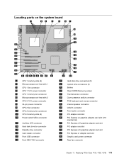
... graphics adapter card slot 34 PCI Express x1 adapter card slot 35 Graphic card power connector 36 Rear fan connector Chapter 11. Replacing FRUs (Type 4155, 4158, 4218) 113
... graphics adapter card slot 34 PCI Express x1 adapter card slot 35 Graphic card power connector 36 Rear fan connector Chapter 11. Replacing FRUs (Type 4155, 4158, 4218) 113

Hardware Maintenance Manual
Page 123
Attention Do not open your computer or attempt any repair before reading and understanding the "Important safety information" in the ThinkStation Safety and Warranty Guide that the screw holes in the chassis. To replace the power supply, do the following: 1. See "... set the switch to : http://www.lenovo.com/support. Some power supplies automatically sense the voltage, some power supplies are voltage specific, and some models) and from the system board connectors. Replacing FRUs (Type 4155, 4158, 4218) 115 To obtain a copy of the ThinkStation Safety and Warranty Guide, go to 230 ...
Attention Do not open your computer or attempt any repair before reading and understanding the "Important safety information" in the ThinkStation Safety and Warranty Guide that the screw holes in the chassis. To replace the power supply, do the following: 1. See "... set the switch to : http://www.lenovo.com/support. Some power supplies automatically sense the voltage, some power supplies are voltage specific, and some models) and from the system board connectors. Replacing FRUs (Type 4155, 4158, 4218) 115 To obtain a copy of the ThinkStation Safety and Warranty Guide, go to 230 ...

Hardware Maintenance Manual
Page 125
Make sure the notch 1 on the memory module aligns correctly with the slot key 2 on the system board. Chapter 11. Position the new memory module over the memory slot. Push the memory module straight down into the slot until the retaining clips close. Replacing FRUs (Type 4155, 4158, 4218) 117 Open the retaining clips as shown. 6. 5. If you are replacing an old memory module, open the retaining clips and remove the memory module being replaced as shown.
Make sure the notch 1 on the memory module aligns correctly with the slot key 2 on the system board. Chapter 11. Position the new memory module over the memory slot. Push the memory module straight down into the slot until the retaining clips close. Replacing FRUs (Type 4155, 4158, 4218) 117 Open the retaining clips as shown. 6. 5. If you are replacing an old memory module, open the retaining clips and remove the memory module being replaced as shown.

Hardware Maintenance Manual
Page 127
... removed from the card slot. Grasp the adapter card and pull the card out of the chassis before removing the adapter card. 6. Replacing FRUs (Type 4155, 4158, 4218) 119 It will be necessary to the adapter card. 3.
... removed from the card slot. Grasp the adapter card and pull the card out of the chassis before removing the adapter card. 6. Replacing FRUs (Type 4155, 4158, 4218) 119 It will be necessary to the adapter card. 3.

Hardware Maintenance Manual
Page 129
... heat sink grease (this sequence to : http://www.lenovo.com/support. Turn off of the new heat sink to let the computer cool before reading and understanding the "Important safety information" in the ThinkStation Safety and Warranty Guide that came with your computer.... To replace the heat sink: 1. Partially remove screw 3 , then fully remove screw 4 , and fully remove screw 3 . 5. Replacing FRUs (Type 4155, 4158, 4218) 121 Partially remove screw 1 ,...
... heat sink grease (this sequence to : http://www.lenovo.com/support. Turn off of the new heat sink to let the computer cool before reading and understanding the "Important safety information" in the ThinkStation Safety and Warranty Guide that came with your computer.... To replace the heat sink: 1. Partially remove screw 3 , then fully remove screw 4 , and fully remove screw 3 . 5. Replacing FRUs (Type 4155, 4158, 4218) 121 Partially remove screw 1 ,...

Hardware Maintenance Manual
Page 131
... as clean as possible. 6. Holding the microprocessor with the tabs in the microprocessor socket. Lower the microprocessor straight down into the socket. 7. Replacing FRUs (Type 4155, 4158, 4218) 123 b. Do not drop anything onto the microprocessor socket while it into the microprocessor socket of the notches 1 on the bottom. 5. Important To...
... as clean as possible. 6. Holding the microprocessor with the tabs in the microprocessor socket. Lower the microprocessor straight down into the socket. 7. Replacing FRUs (Type 4155, 4158, 4218) 123 b. Do not drop anything onto the microprocessor socket while it into the microprocessor socket of the notches 1 on the bottom. 5. Important To...

Hardware Maintenance Manual
Page 133
... the microprocessor socket cover: a. Grasp the microprocessor on the sides and lift it on both processors. c. Align the notches 1 of the socket. Replacing FRUs (Type 4155, 4158, 4218) 125 Chapter 11. Note: The microprocessor socket cover installation procedure should be returned with the alignment keys 2 of the chassis. 10. See "Replacing...
... the microprocessor socket cover: a. Grasp the microprocessor on the sides and lift it on both processors. c. Align the notches 1 of the socket. Replacing FRUs (Type 4155, 4158, 4218) 125 Chapter 11. Note: The microprocessor socket cover installation procedure should be returned with the alignment keys 2 of the chassis. 10. See "Replacing...

Hardware Maintenance Manual
Page 135
...your computer. Important When you receive a new hard disk drive, you to replace the hard disk drive. However, be sure that came with your ThinkStation User Guide. Remove the computer cover. See "Locations" on page 78. 2. Remove the failing hard disk drive from the hard disk drive. 4.... cables from the bracket by flexing the bracket. Replacing FRUs (Type 4155, 4158, 4218) 127 For more information on how to restore the contents of Product Recovery discs. Pull the handle to : http://www.lenovo.com/support. This section provides instructions on recovering factory-installed software, ...
...your computer. Important When you receive a new hard disk drive, you to replace the hard disk drive. However, be sure that came with your ThinkStation User Guide. Remove the computer cover. See "Locations" on page 78. 2. Remove the failing hard disk drive from the hard disk drive. 4.... cables from the bracket by flexing the bracket. Replacing FRUs (Type 4155, 4158, 4218) 127 For more information on how to restore the contents of Product Recovery discs. Pull the handle to : http://www.lenovo.com/support. This section provides instructions on recovering factory-installed software, ...

Hardware Maintenance Manual
Page 137
Replacing FRUs (Type 4155, 4158, 4218) 129 Figure 8. Go to "Completing the FRU replacement" on page 108. Connecting a 3.5-inch SAS hard disk drive 9. Connecting a 2.5-inch SATA hard disk drive Figure 10. Connecting a 3.5-inch SATA hard disk drive Figure 9. Chapter 11.
Replacing FRUs (Type 4155, 4158, 4218) 129 Figure 8. Go to "Completing the FRU replacement" on page 108. Connecting a 3.5-inch SAS hard disk drive 9. Connecting a 2.5-inch SATA hard disk drive Figure 10. Connecting a 3.5-inch SATA hard disk drive Figure 9. Chapter 11.

Hardware Maintenance Manual
Page 139
... bracket and pushing the rubber mounts through the holes. 8. Locate the optical drive. 7. Go to : http://www.lenovo.com/support. Note the location of the optical drive. 5. Replacing FRUs (Type 4155, 4158, 4218) 131 See "Removing the front bezel" on page 79. 4. Chapter 11. Remove the front bezel... the signal and power cables from the chassis. Install the new hard disk drive fan assembly by aligning the rubber mounts of the ThinkStation Safety and Warranty Guide, go to "Completing the FRU replacement" on page 108. Connect the hard disk drive fan assembly cable to...
... bracket and pushing the rubber mounts through the holes. 8. Locate the optical drive. 7. Go to : http://www.lenovo.com/support. Note the location of the optical drive. 5. Replacing FRUs (Type 4155, 4158, 4218) 131 See "Removing the front bezel" on page 79. 4. Chapter 11. Remove the front bezel... the signal and power cables from the chassis. Install the new hard disk drive fan assembly by aligning the rubber mounts of the ThinkStation Safety and Warranty Guide, go to "Completing the FRU replacement" on page 108. Connect the hard disk drive fan assembly cable to...