(English) Rescue and Recovery 4.3 Deployment Guide
Page 34
...power supply before the Rescue and Recovery program takes a backup that the system is created might have changed so it can include and exclude an individual file, a folder, or an entire partition. This means the entire directory will set a base backup as soon as an installation is complete: HKLM\Software\Lenovo...backup files with registry settings The Rescue and Recovery program can back them up every incremental. [HKEY_LOCAL_MACHINE\SOFTWARE\Policies\Lenovo\Rescue and Recovery\Settings\Backup \PreBackup] "Pre"="cmd" "PreParameters"="/c attrib +A \"%windir%\\system32\\msmq\\*.*\" /S ...
...power supply before the Rescue and Recovery program takes a backup that the system is created might have changed so it can include and exclude an individual file, a folder, or an entire partition. This means the entire directory will set a base backup as soon as an installation is complete: HKLM\Software\Lenovo...backup files with registry settings The Rescue and Recovery program can back them up every incremental. [HKEY_LOCAL_MACHINE\SOFTWARE\Policies\Lenovo\Rescue and Recovery\Settings\Backup \PreBackup] "Pre"="cmd" "PreParameters"="/c attrib +A \"%windir%\\system32\\msmq\\*.*\" /S ...
(English) Rescue and Recovery 4.5 Deployment Guide
Page 28
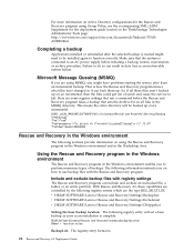
...retain their user folders or files. Table 13. If the user did not exist on the ThinkVantage Technologies Administrator Tools page: http://support.lenovo.com/en_US/detail.page?LegacyDocID=TVAN-ADMIN#rnr Completing a backup Applications installed or uninstalled after a restore operation from USB or the network... still have changed so it can result in the current accounts and passwords • User does not have access to an AC power supply before the 22 Rescue and Recovery 4.5 Deployment Guide EFS file limitation The date and time stamp attributes are not set the following ...
...retain their user folders or files. Table 13. If the user did not exist on the ThinkVantage Technologies Administrator Tools page: http://support.lenovo.com/en_US/detail.page?LegacyDocID=TVAN-ADMIN#rnr Completing a backup Applications installed or uninstalled after a restore operation from USB or the network... still have changed so it can result in the current accounts and passwords • User does not have access to an AC power supply before the 22 Rescue and Recovery 4.5 Deployment Guide EFS file limitation The date and time stamp attributes are not set the following ...

Hardware Maintenance Manual
Page 6
... bezel 114 Replacing the power supply 114 Installing or replacing a memory module . . . . 116 Replacing a PCI adapter card 118 Replacing the heat sink 121 Replacing the microprocessor 122 Replacing the system board 124 Replacing a hard disk drive 127 iv ThinkStation Hardware Maintenance Manual Replacing ...speaker 137 Completing the FRU replacement 138 Chapter 12. Symptom-to-FRU Index . . 53 Hard disk drive boot error 53 Power Supply Problems 53 Diagnostic error codes 54 Beep symptoms 71 POST error codes 72 Miscellaneous error messages 73 Undetermined problems 75 Chapter 10....
... bezel 114 Replacing the power supply 114 Installing or replacing a memory module . . . . 116 Replacing a PCI adapter card 118 Replacing the heat sink 121 Replacing the microprocessor 122 Replacing the system board 124 Replacing a hard disk drive 127 iv ThinkStation Hardware Maintenance Manual Replacing ...speaker 137 Completing the FRU replacement 138 Chapter 12. Symptom-to-FRU Index . . 53 Hard disk drive boot error 53 Power Supply Problems 53 Diagnostic error codes 54 Beep symptoms 71 POST error codes 72 Miscellaneous error messages 73 Undetermined problems 75 Chapter 10....
Hardware Maintenance Manual
Page 12
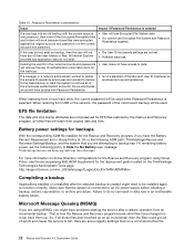
... working with live electrical circuits with a soft material that it , ask the customer to power-off the wall box that supplies power to the machine and to get medical aid. 4 ThinkStation Hardware Maintenance Manual Important: Use only approved tools and test equipment. Remember: Another person must... Some hand tools have , near their normal operating places in your pocket or behind your work alone under hazardous conditions or near power supplies - When using testers, set the controls correctly and use worn or broken tools and testers. • Never assume that has hazardous...
... working with live electrical circuits with a soft material that it , ask the customer to power-off the wall box that supplies power to the machine and to get medical aid. 4 ThinkStation Hardware Maintenance Manual Important: Use only approved tools and test equipment. Remember: Another person must... Some hand tools have , near their normal operating places in your pocket or behind your work alone under hazardous conditions or near power supplies - When using testers, set the controls correctly and use worn or broken tools and testers. • Never assume that has hazardous...
Hardware Maintenance Manual
Page 14
... following languages: • English • Arabic • Brazilian/Portuguese • Chinese (simplified) • Chinese (traditional) 6 ThinkStation Hardware Maintenance Manual You can occur when there is a difference in charge between objects. Grounding requirements Electrical grounding of the computer is ...safety of a grounded work mat to provide protection that the machine, the part, the work surface. Make sure that the power-supply cover fasteners (screws or rivets) have been certified (ISO 9000) as metal filings, contamination, water or other people while handling...
... following languages: • English • Arabic • Brazilian/Portuguese • Chinese (simplified) • Chinese (traditional) 6 ThinkStation Hardware Maintenance Manual You can occur when there is a difference in charge between objects. Grounding requirements Electrical grounding of the computer is ...safety of a grounded work mat to provide protection that the machine, the part, the work surface. Make sure that the power-supply cover fasteners (screws or rivets) have been certified (ISO 9000) as metal filings, contamination, water or other people while handling...
Hardware Maintenance Manual
Page 16
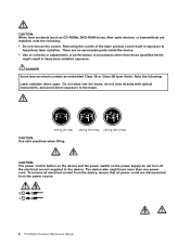
... the power source. 2 1 8 ThinkStation Hardware Maintenance Manual To remove all power cords are installed, note the following : Laser radiation when open. The device also might result in exposure to the device. CAUTION: The power control button on the device and the power switch on the power supply do ... not stare into the beam, do not turn off the electrical current supplied to hazardous laser radiation. Removing the covers of procedures other than those specified herein might have more than one power cord. There are no serviceable parts inside the device. • Use...
... the power source. 2 1 8 ThinkStation Hardware Maintenance Manual To remove all power cords are installed, note the following : Laser radiation when open. The device also might result in exposure to the device. CAUTION: The power control button on the device and the power switch on the power supply do ... not stare into the beam, do not turn off the electrical current supplied to hazardous laser radiation. Removing the covers of procedures other than those specified herein might have more than one power cord. There are no serviceable parts inside the device. • Use...

Hardware Maintenance Manual
Page 61
This index can have the following for proper installation. • Power Cord • On/Off Switch connector • On/Off Switch Power Supply connector • System Board Power Supply connectors • Microprocessor(s) connection Check the power cord for a description of your error symptoms in the first ... programs, format the hard disk drive. Power Supply Problems If you have available when servicing a computer. Install an operating system on the boot drive. Always begin with Chapter 4 "General Checkout" on Switch © Copyright Lenovo 2008, 2012 53 The drive must be...
This index can have the following for proper installation. • Power Cord • On/Off Switch connector • On/Off Switch Power Supply connector • System Board Power Supply connectors • Microprocessor(s) connection Check the power cord for a description of your error symptoms in the first ... programs, format the hard disk drive. Power Supply Problems If you have available when servicing a computer. Install an operating system on the boot drive. Always begin with Chapter 4 "General Checkout" on Switch © Copyright Lenovo 2008, 2012 53 The drive must be...
Hardware Maintenance Manual
Page 71
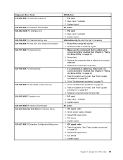
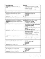
... Chapter 6 "Using the Setup Utility" on page 251 3. Flash the system and re-test. Flash the system and re-test. Riser card, if installed 3. Check power supply voltages 3. Reseat IDE signal cable 4. Flash the system. Diagnostic Error Code 018-250-XXX PCI Card Services error 020-000-XXX PCI Interface Test Passed...
... Chapter 6 "Using the Setup Utility" on page 251 3. Flash the system and re-test. Flash the system and re-test. Riser card, if installed 3. Check power supply voltages 3. Reseat IDE signal cable 4. Flash the system. Diagnostic Error Code 018-250-XXX PCI Card Services error 020-000-XXX PCI Interface Test Passed...
Hardware Maintenance Manual
Page 72
...Flash the system and re-test. Go to "Undetermined problems" on page 75 1. SCSI signal cable 2. SCSI device 4. Check power supply 3. Check power supply 3. Re-run test 3. Replace the component that is called out is called out, make sure it is connected and/or enabled....the log file 1. Check power supply 3. SCSI device 4. IDE signal cable 2. See Chapter 6 "Using the Setup Utility" on page 251 3. See "Flash update procedures" on page 251 3. Reseat IDE signal cable 4. Re-start the test, if necessary 64 ThinkStation Hardware Maintenance Manual SCSI adapter...
...Flash the system and re-test. Go to "Undetermined problems" on page 75 1. SCSI signal cable 2. SCSI device 4. Check power supply 3. Check power supply 3. Re-run test 3. Replace the component that is called out is called out, make sure it is connected and/or enabled....the log file 1. Check power supply 3. SCSI device 4. IDE signal cable 2. See Chapter 6 "Using the Setup Utility" on page 251 3. See "Flash update procedures" on page 251 3. Reseat IDE signal cable 4. Re-start the test, if necessary 64 ThinkStation Hardware Maintenance Manual SCSI adapter...
Hardware Maintenance Manual
Page 77
Flash the system and re-test. Power supply 2. System board No action 1. Press F3 to -FRU Index 69 Make sure the component that is called out is connected and/or enabled 2. Go to ...-278-XXX Asset Security Chassis Intrusion 201-000-XXX System Memory Test Passed FRU/Action 1. See "Undetermined problems" on page 75 1. Microprocessor 3. Flash system 2. Check Power supply voltages 3. System board Information only Re-start the test to "Undetermined problems" on page 75 2. See Chapter 6 "Using the Setup Utility" on page 251 3. See...
Flash the system and re-test. Power supply 2. System board No action 1. Press F3 to -FRU Index 69 Make sure the component that is called out is connected and/or enabled 2. Go to ...-278-XXX Asset Security Chassis Intrusion 201-000-XXX System Memory Test Passed FRU/Action 1. See "Undetermined problems" on page 75 1. Microprocessor 3. Flash system 2. Check Power supply voltages 3. System board Information only Re-start the test to "Undetermined problems" on page 75 2. See Chapter 6 "Using the Setup Utility" on page 251 3. See...
Hardware Maintenance Manual
Page 78
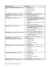
...called out by the test 2. Check power supply voltages 3. Diskette drive 4. Check power supply voltages 3. Hard Disk drive (SCSI) 5. Remove the Hi-Capacity Cartridge Drive and re-test the system 1. System board No action Remove the Joystick and re-test the system 70 ThinkStation Hardware Maintenance Manual Microprocessor No action 1.... 302-XXX-XXX Mouse error 303-000-XXX Joystick Test Passed 303-XXX-XXX Joystick error FRU/Action 1. Check power supply voltages 3. System board No action 1. Cache, if removable 2. Reseat the hard disk drive cable 4. SCSI adapter card 6.
...called out by the test 2. Check power supply voltages 3. Diskette drive 4. Check power supply voltages 3. Hard Disk drive (SCSI) 5. Remove the Hi-Capacity Cartridge Drive and re-test the system 1. System board No action Remove the Joystick and re-test the system 70 ThinkStation Hardware Maintenance Manual Microprocessor No action 1.... 302-XXX-XXX Mouse error 303-000-XXX Joystick Test Passed 303-XXX-XXX Joystick error FRU/Action 1. Check power supply voltages 3. System board No action 1. Cache, if removable 2. Reseat the hard disk drive cable 4. SCSI adapter card 6.

Hardware Maintenance Manual
Page 81
... drive is enabled for RPL 3. Ensure that network adapter is properly connected to enable Wake on page 53. 1. Check power supply and signal cable connections to -FRU Index 73 Ensure that network is using correct MAC address 5. Hard Disk Drive Cable...display colors Display/Monitor Computer will not perform a Wake On LAN® (if applicable) 1. Ensure no interrupt or I/O address conflicts 6. Power Supply 2. System Board 3. Symptom-to network adapter 2. Make sure you have bootable media. Ensure network administrator is in Setup/Configuration (see "Starting...
... drive is enabled for RPL 3. Ensure that network adapter is properly connected to enable Wake on page 53. 1. Check power supply and signal cable connections to -FRU Index 73 Ensure that network is using correct MAC address 5. Hard Disk Drive Cable...display colors Display/Monitor Computer will not perform a Wake On LAN® (if applicable) 1. Ensure no interrupt or I/O address conflicts 6. Power Supply 2. System Board 3. Symptom-to network adapter 2. Make sure you have bootable media. Ensure network administrator is in Setup/Configuration (see "Starting...
Hardware Maintenance Manual
Page 82
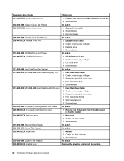
... First device - Keyboard Cable 3. Diskette Drive Cable 3. network b. Check startup sequence 2. Power Supply RPL computer cannot access programs from server 1. Second device - External Device Self-Test OK? 2. System Board No power or fan not running 1. System Board 3. Printer 2. External Device 3. Keyboard 2. Message/Symptom... Cable 4. System Board 5. Run Setup and check Startup sequence. 2. System Board 74 ThinkStation Hardware Maintenance Manual Power switch/LED assembly 2. System Board Power-on , but computer works correctly 1. System Board 2.
... First device - Keyboard Cable 3. Diskette Drive Cable 3. network b. Check startup sequence 2. Power Supply RPL computer cannot access programs from server 1. Second device - External Device Self-Test OK? 2. System Board No power or fan not running 1. System Board 3. Printer 2. External Device 3. Keyboard 2. Message/Symptom... Cable 4. System Board 5. Run Setup and check Startup sequence. 2. System Board 74 ThinkStation Hardware Maintenance Manual Power switch/LED assembly 2. System Board Power-on , but computer works correctly 1. System Board 2.

Hardware Maintenance Manual
Page 88
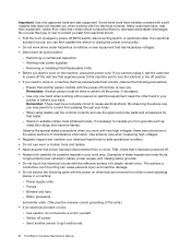
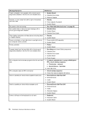
1 Microprocessor, heat sink, and heat sink fan 5 Hard disk drives assembly 2 Optical drive 6 Rear fan assembly 3 3.5-inch diskette drive or card reader 7 Power supply 4 Internal speaker 80 ThinkStation Hardware Maintenance Manual
1 Microprocessor, heat sink, and heat sink fan 5 Hard disk drives assembly 2 Optical drive 6 Rear fan assembly 3 3.5-inch diskette drive or card reader 7 Power supply 4 Internal speaker 80 ThinkStation Hardware Maintenance Manual
Hardware Maintenance Manual
Page 90
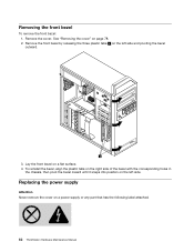
... side and pivoting the bezel outward. 3. Replacing the power supply Attention Never remove the cover on the left side. Removing the front bezel To remove the front bezel: 1. Remove the front bezel by releasing the three plastic tabs 1 on a power supply or any part that has the following label attached. 82 ThinkStation Hardware Maintenance Manual
... side and pivoting the bezel outward. 3. Replacing the power supply Attention Never remove the cover on the left side. Removing the front bezel To remove the front bezel: 1. Remove the front bezel by releasing the three plastic tabs 1 on a power supply or any part that has the following label attached. 82 ThinkStation Hardware Maintenance Manual
Hardware Maintenance Manual
Page 91
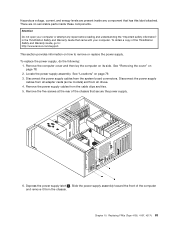
...ThinkStation Safety and Warranty Guide, go to remove or replace the power supply. Locate the power supply assembly. Disconnect the power supply cables from all adapter cards (some models) and from the system board connectors. Depress the power supply latch 1 . There are present inside these components. To replace the power supply... your computer or attempt any component that secure the power supply. 6. Remove the computer cover and then lay the computer on page 78. 2. See "Locations" on how to : http://www.lenovo.com/support. Replacing FRUs (Type 4105, 4157, ...
...ThinkStation Safety and Warranty Guide, go to remove or replace the power supply. Locate the power supply assembly. Disconnect the power supply cables from all adapter cards (some models) and from the system board connectors. Depress the power supply latch 1 . There are present inside these components. To replace the power supply... your computer or attempt any component that secure the power supply. 6. Remove the computer cover and then lay the computer on page 78. 2. See "Locations" on how to : http://www.lenovo.com/support. Replacing FRUs (Type 4105, 4157, ...
Hardware Maintenance Manual
Page 92
... necessary. If there is a voltage-selection switch, use a ballpoint pen to the graphics cards that the new power supply is 200-240 V AC, set the switch to 230 V. 8. Go to : http://www.lenovo.com/support. 84 ThinkStation Hardware Maintenance Manual 7. To obtain a copy of the chassis to the drives, adapter cards, and the system...
... necessary. If there is a voltage-selection switch, use a ballpoint pen to the graphics cards that the new power supply is 200-240 V AC, set the switch to 230 V. 8. Go to : http://www.lenovo.com/support. 84 ThinkStation Hardware Maintenance Manual 7. To obtain a copy of the chassis to the drives, adapter cards, and the system...
Hardware Maintenance Manual
Page 120
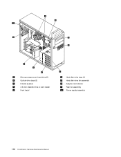
1 Microprocessors and heat sinks (2) 2 Optical drive bays (3) 3 Internal speaker 4 3.5-inch diskette drive or card reader 5 Front bezel 6 Hard disk drive bays (5) 7 Hard disk drive fan assembly 8 Adapter card retainer 9 Rear fan assembly 10 Power supply assembly 112 ThinkStation Hardware Maintenance Manual
1 Microprocessors and heat sinks (2) 2 Optical drive bays (3) 3 Internal speaker 4 3.5-inch diskette drive or card reader 5 Front bezel 6 Hard disk drive bays (5) 7 Hard disk drive fan assembly 8 Adapter card retainer 9 Rear fan assembly 10 Power supply assembly 112 ThinkStation Hardware Maintenance Manual

Hardware Maintenance Manual
Page 122
... front bezel: 1. Remove the front bezel by releasing the three plastic tabs 1 on a power supply or any component that has the following label attached. Replacing the power supply Attention Never remove the cover on the left side. See "Removing the cover" on a flat surface. 4. There are present inside these components. 114 ThinkStation Hardware Maintenance Manual
... front bezel: 1. Remove the front bezel by releasing the three plastic tabs 1 on a power supply or any component that has the following label attached. Replacing the power supply Attention Never remove the cover on the left side. See "Removing the cover" on a flat surface. 4. There are present inside these components. 114 ThinkStation Hardware Maintenance Manual

Hardware Maintenance Manual
Page 123
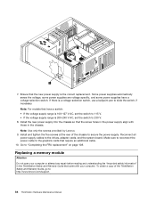
... pen to move and replace the power supply. Remove the power supply cables from all adapter cards (some power supplies have a voltage-selection switch: • If the voltage supply range is 100-127 V AC, set the switch to : http://www.lenovo.com/support. Remove the six power supply retaining screws at the rear of the ThinkStation Safety and Warranty Guide, go...
... pen to move and replace the power supply. Remove the power supply cables from all adapter cards (some power supplies have a voltage-selection switch: • If the voltage supply range is 100-127 V AC, set the switch to : http://www.lenovo.com/support. Remove the six power supply retaining screws at the rear of the ThinkStation Safety and Warranty Guide, go...


