User Manual
Page 5
... Opening the cover 94 Removing the front bezel 95 Accessing system board components and drives . . 96 Replacing the battery 98 Replacing the power supply assembly . . . . . 99 Replacing an adapter card 103 Replacing the heat sink 105 Replacing the microprocessor 107 Replacing the system ... 119 Replacing the internal speaker 120 Replacing the front panel connector assembly . . 121 Completing the FRU replacement 123 © Copyright Lenovo 2006, 2008 iii Installing and configuring RAID 53 Attaching SATA hard disk drives 53 Configuring the system BIOS to enable embedded SATA RAID...
... Opening the cover 94 Removing the front bezel 95 Accessing system board components and drives . . 96 Replacing the battery 98 Replacing the power supply assembly . . . . . 99 Replacing an adapter card 103 Replacing the heat sink 105 Replacing the microprocessor 107 Replacing the system ... 119 Replacing the internal speaker 120 Replacing the front panel connector assembly . . 121 Completing the FRU replacement 123 © Copyright Lenovo 2006, 2008 iii Installing and configuring RAID 53 Attaching SATA hard disk drives 53 Configuring the system BIOS to enable embedded SATA RAID...
User Manual
Page 6
...flashing) BIOS from the operating system 236 Recovering from a POST/BIOS update failure . . 236 Power management 238 Automatic configuration and power interface (ACPI) BIOS 238 Automatic Power-On features 238 Appendix. FRU lists 159 Machine Type 6423 159 Machine Type 6427 175 Machine Type ... . 129 Opening the cover 130 Removing the front bezel 132 Accessing system board components and drives 133 Replacing the battery 135 Replacing the power supply assembly . . . . . 136 Replacing an adapter card 139 Replacing the heat sink 141 Replacing the microprocessor 143 Replacing the system ...
...flashing) BIOS from the operating system 236 Recovering from a POST/BIOS update failure . . 236 Power management 238 Automatic configuration and power interface (ACPI) BIOS 238 Automatic Power-On features 238 Appendix. FRU lists 159 Machine Type 6423 159 Machine Type 6427 175 Machine Type ... . 129 Opening the cover 130 Removing the front bezel 132 Accessing system board components and drives 133 Replacing the battery 135 Replacing the power supply assembly . . . . . 136 Replacing an adapter card 139 Replacing the heat sink 141 Replacing the microprocessor 143 Replacing the system ...

User Manual
Page 10
...condition. these instructions are in the installation and configuration procedures. Important: Use only approved tools and test equipment. v Find the room emergency power-off position. Performing a mechanical inspection - v If you need to lock the wall box in your pocket or behind your back. v... v Before you start to insulate you cannot unplug it has been powered-off controls, is near power supplies - If you from grounds such as metal floor strips and machine frames. Ensure that supplies power to the machine and to work alone under hazardous conditions or near their...
...condition. these instructions are in the installation and configuration procedures. Important: Use only approved tools and test equipment. v Find the room emergency power-off position. Performing a mechanical inspection - v If you need to lock the wall box in your pocket or behind your back. v... v Before you start to insulate you cannot unplug it has been powered-off controls, is near power supplies - If you from grounds such as metal floor strips and machine frames. Ensure that supplies power to the machine and to work alone under hazardous conditions or near their...

User Manual
Page 11
... built, had required safety items installed to another person to the computer. Voltage-selection switch Some computers are equipped with the power on the computer. Chapter 2. The surface is set the switch to match the voltage available at your electrical outlet, contact...information 5 If you set to match the voltage provided in that the voltage provided is designed to attachment of a plastic dental mirror. Power supply units - Each machine, as it was originally purchased. If your computer has a voltage-selection switch, ensure that the voltage-selection switch...
... built, had required safety items installed to another person to the computer. Voltage-selection switch Some computers are equipped with the power on the computer. Chapter 2. The surface is set the switch to match the voltage available at your electrical outlet, contact...information 5 If you set to match the voltage provided in that the voltage provided is designed to attachment of a plastic dental mirror. Power supply units - Each machine, as it was originally purchased. If your computer has a voltage-selection switch, ensure that the voltage-selection switch...
User Manual
Page 12
...wrist strap against ESD damage by equalizing the charge so that the power-supply cover fasteners (screws or rivets) have been certified (ISO 9000) as specified in the parts listings. Checklist: 1. The power cord should be considered sensitive to eliminate static on the frame can... handling the part are inserted into the product. Use product-specific ESD procedures when they present: v Electrical hazards, especially primary power (primary voltage on your skin to electrostatic discharge (ESD). Consider these conditions and the safety hazards they exceed the requirements noted ...
...wrist strap against ESD damage by equalizing the charge so that the power-supply cover fasteners (screws or rivets) have been certified (ISO 9000) as specified in the parts listings. Checklist: 1. The power cord should be considered sensitive to eliminate static on the frame can... handling the part are inserted into the product. Use product-specific ESD procedures when they present: v Electrical hazards, especially primary power (primary voltage on your skin to electrostatic discharge (ESD). Consider these conditions and the safety hazards they exceed the requirements noted ...

User Manual
Page 16
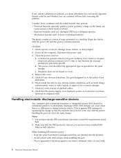
CAUTION: The power control button on the device and the power switch on the power supply do not turn off the electrical current supplied to the device. To remove all electrical current from the device, ensure that all power cords are disconnected from the power source. 2 1 10 Hardware Maintenance Manual The device also might have more than one power cord.
CAUTION: The power control button on the device and the power switch on the power supply do not turn off the electrical current supplied to the device. To remove all electrical current from the device, ensure that all power cords are disconnected from the power source. 2 1 10 Hardware Maintenance Manual The device also might have more than one power cord.
User Manual
Page 65
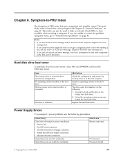
.... Install an operating system on Switch © Copyright Lenovo 2006, 2008 59 Using the operating systems programs, format the hard disk drive. Check/Verify Check the following : 1. FRU/Action Reseat connectors Power Cord Power-on the boot drive. Error The start-up drive ... part of this index, go to have available when servicing a computer. Attempt to -FRU index lists error symptoms and possible causes. Power Supply Errors If you have the following procedures. Chapter 8. Always begin with Chapter 4, "General Checkout," on the failing hard disk drive....
.... Install an operating system on Switch © Copyright Lenovo 2006, 2008 59 Using the operating systems programs, format the hard disk drive. Check/Verify Check the following : 1. FRU/Action Reseat connectors Power Cord Power-on the boot drive. Error The start-up drive ... part of this index, go to have available when servicing a computer. Attempt to -FRU index lists error symptoms and possible causes. Power Supply Errors If you have the following procedures. Chapter 8. Always begin with Chapter 4, "General Checkout," on the failing hard disk drive....

User Manual
Page 66
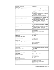
... the two diagnostic LEDs are located on the computer. 3. v Check the power cord for continuity. Power-on the power supply at a time, until the computer works correctly. 60 Hardware Maintenance Manual OFF v Make sure the power cord is attached to the following table: Green diagnostic LED ON OFF ON... Yellow diagnostic LED Action OFF This is OK. v If the problem persists, replace the power supply. There are three LEDs to help you determine if the power supply and system board are in the normal condition and the problem persists, replace the system board and the ...
... the two diagnostic LEDs are located on the computer. 3. v Check the power cord for continuity. Power-on the power supply at a time, until the computer works correctly. 60 Hardware Maintenance Manual OFF v Make sure the power cord is attached to the following table: Green diagnostic LED ON OFF ON... Yellow diagnostic LED Action OFF This is OK. v If the problem persists, replace the power supply. There are three LEDs to help you determine if the power supply and system board are in the normal condition and the problem persists, replace the system board and the ...

User Manual
Page 78
...component is called out, make sure it is connected and/or enabled. Replace component under test Riser card, if installed 3. Check power supply voltages 3. IDE signal cable 2. Flash the system. Re-run test 3. Diagnostic Error Code 020-198-XXX PCI test aborted 020-... function test 1. IDE device 5. PCI card 2. See Chapter 6, "Using the Setup Utility," on page 235 3. Reseat IDE signal cable 4. Check power supply 3. Replace the component that is called out in warning statement 4. See Chapter 6, "Using the Setup Utility," on page 86 2. Go to review the...
...component is called out, make sure it is connected and/or enabled. Replace component under test Riser card, if installed 3. Check power supply voltages 3. IDE signal cable 2. Flash the system. Re-run test 3. Diagnostic Error Code 020-198-XXX PCI test aborted 020-... function test 1. IDE device 5. PCI card 2. See Chapter 6, "Using the Setup Utility," on page 235 3. Reseat IDE signal cable 4. Check power supply 3. Replace the component that is called out in warning statement 4. See Chapter 6, "Using the Setup Utility," on page 86 2. Go to review the...

User Manual
Page 79
Replace component under test Chapter 8. Flash the system. SCSI adapter card, if installed 5. Check power supply 3. Press F3 to -FRU Index 73 If a component is called out in warning statement 4. Go to "Undetermined problems" on page 86 2. SCSI device 4. System board 1. ... test halt, error threshold exceeded 030-197-XXX SCSI interface test warning FRU/Action 1. See "Flash update procedures" on page 235 3. SCSI signal cable 2. Check power supply 3. Make sure the component that is called out, make sure it is connected and/or enabled. Symptom-to review the log file 2.
Replace component under test Chapter 8. Flash the system. SCSI adapter card, if installed 5. Check power supply 3. Press F3 to -FRU Index 73 If a component is called out in warning statement 4. Go to "Undetermined problems" on page 86 2. SCSI device 4. System board 1. ... test halt, error threshold exceeded 030-197-XXX SCSI interface test warning FRU/Action 1. See "Flash update procedures" on page 235 3. SCSI signal cable 2. Check power supply 3. Make sure the component that is called out, make sure it is connected and/or enabled. Symptom-to review the log file 2.

User Manual
Page 84
... Thermal Sensor(s) failure 1. Press F3 to review the log file 2. See "Undetermined problems" on page 86 170-199-XXX Voltage Sensor(s) test failed, cause unknown 1. Power supply 2. Microprocessor 3. Re-start the test, if necessary 170-196-XXX Voltage Sensor(s) test halt, error threshold exceeded 1. Flash the system and re-test. Go to...
... Thermal Sensor(s) failure 1. Press F3 to review the log file 2. See "Undetermined problems" on page 86 170-199-XXX Voltage Sensor(s) test failed, cause unknown 1. Power supply 2. Microprocessor 3. Re-start the test, if necessary 170-196-XXX Voltage Sensor(s) test halt, error threshold exceeded 1. Flash the system and re-test. Go to...
User Manual
Page 85
...2. Flash the system and re-test. Flash the system and re-test. Cache, if removable 2. Diskette Drive Cable 2. Check power supply voltages 3. C2 Cover Switch 3. Microprocessor No action 1. System board Chapter 8. Flash system 2. System board No action 1. See "Flash ...update procedures" on page 49 2. Check Power supply voltages 3. Microprocessor 4. System board No action 1. Assure Asset Security Enabled 2. System board No action 1. See Chapter 6, "Using the Setup...
...2. Flash the system and re-test. Flash the system and re-test. Cache, if removable 2. Diskette Drive Cable 2. Check power supply voltages 3. C2 Cover Switch 3. Microprocessor No action 1. System board Chapter 8. Flash system 2. System board No action 1. See "Flash ...update procedures" on page 49 2. Check Power supply voltages 3. Microprocessor 4. System board No action 1. Assure Asset Security Enabled 2. System board No action 1. See Chapter 6, "Using the Setup...

User Manual
Page 86
...error 305-000-XXX Monitor DDC Test Passed 305-250-XXX Monitor DDC self test failure FRU/Action No action 1. Check power supply voltages 3. Hard Disk drive (IDE) 5. Check power supply voltages 3. System board No action 1. System board No action No action 1. Cable 3. Keyboard 2. Video card 5. ... the hard disk drive cable 4. Remove the Hi-Capacity Cartridge Drive and re-test the system 1. Run Setup to enable DDC 2. Check power supply voltages 3. Hard Disk Drive Cable 2. System board 1. Check and test mouse 3. System board 80 Hardware Maintenance Manual Mouse 2. SCSI adapter ...
...error 305-000-XXX Monitor DDC Test Passed 305-250-XXX Monitor DDC self test failure FRU/Action No action 1. Check power supply voltages 3. Hard Disk drive (IDE) 5. Check power supply voltages 3. System board No action 1. System board No action No action 1. Cable 3. Keyboard 2. Video card 5. ... the hard disk drive cable 4. Remove the Hi-Capacity Cartridge Drive and re-test the system 1. Run Setup to enable DDC 2. Check power supply voltages 3. Hard Disk Drive Cable 2. System board 1. Check and test mouse 3. System board 80 Hardware Maintenance Manual Mouse 2. SCSI adapter ...
User Manual
Page 91
... Memory tests 2. System Board 1. Intensity or color varies from server Computer will not perform a Wake on page 49) 4. Power Switch 2. Check power supply and signal cable connections to enable Wake on or does not light when drive is enabled in the first 3.5-inch diskette drive....-FRU Index 85 Network adapter (Advise network administrator of new MAC address) 1. Hard Disk Drive Cable 1. System Board 2. Display 2. See "Power Supply Errors" on page 59. Primary Hard Disk Drive 3. Video adapter (if present) 3. System Board 1. Incorrect memory size during POST ″Insert...
... Memory tests 2. System Board 1. Intensity or color varies from server Computer will not perform a Wake on page 49) 4. Power Switch 2. Check power supply and signal cable connections to enable Wake on or does not light when drive is enabled in the first 3.5-inch diskette drive....-FRU Index 85 Network adapter (Advise network administrator of new MAC address) 1. Hard Disk Drive Cable 1. System Board 2. Display 2. See "Power Supply Errors" on page 59. Primary Hard Disk Drive 3. Video adapter (if present) 3. System Board 1. Incorrect memory size during POST ″Insert...
User Manual
Page 92
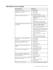
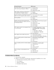
...Serial or parallel port device failure (system board port) 1. External Device 3. Alternate Adapter 5. Memory modules d. Display 2. Power Supply RPL computer cannot access programs from server 1. External devices (modem, printer, or mouse) b. System Board Printer problems ...1. Run Setup and check Startup sequence. 2. Diskette Drive Cable 4. Second device - System Board Undetermined problems 1. Power-off the computer. 2. network b. System Board Serial or parallel port device failure (adapter port) 1. Cable 4. Keyboard Cable 3. a....
...Serial or parallel port device failure (system board port) 1. External Device 3. Alternate Adapter 5. Memory modules d. Display 2. Power Supply RPL computer cannot access programs from server 1. External devices (modem, printer, or mouse) b. System Board Printer problems ...1. Run Setup and check Startup sequence. 2. Diskette Drive Cable 4. Second device - System Board Undetermined problems 1. Power-off the computer. 2. network b. System Board Serial or parallel port device failure (adapter port) 1. Cable 4. Keyboard Cable 3. a....
User Manual
Page 98
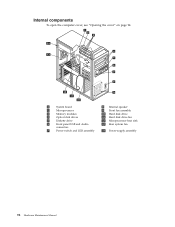
Internal components To open the computer cover, see "Opening the cover" on page 94. 1 System board 8 Internal speaker 2 Microprocessor 9 Front fan assembly 3 Memory modules 10 Hard disk drive 4 Optical disk drives 11 Hard disk drive fan 5 Diskette drive 12 Microprocessor heat sink 6 Front panel USB and Audio 13 Rear system fan connectors 7 Power switch and LED assembly 14 Power-supply assembly 92 Hardware Maintenance Manual
Internal components To open the computer cover, see "Opening the cover" on page 94. 1 System board 8 Internal speaker 2 Microprocessor 9 Front fan assembly 3 Memory modules 10 Hard disk drive 4 Optical disk drives 11 Hard disk drive fan 5 Diskette drive 12 Microprocessor heat sink 6 Front panel USB and Audio 13 Rear system fan connectors 7 Power switch and LED assembly 14 Power-supply assembly 92 Hardware Maintenance Manual

User Manual
Page 105
Locate the power-supply assembly. Chapter 9. Disconnect the power-supply cables 1 , 2 , and 3 from the system-board connectors, all drives. 4. Replacing FRUs (types 6423 and 6483) 99 Open the computer cover. See "Internal components" on page 94. 2. Remove the power-supply cables from all adapter cards (some models) and from the cable clips and ties. 5. Replacing the power supply assembly To replace the power-supply assembly: 1. See "Opening the cover" on page 92. 3. Remove the four screws at the rear of the chassis that secure the power supply.
Locate the power-supply assembly. Chapter 9. Disconnect the power-supply cables 1 , 2 , and 3 from the system-board connectors, all drives. 4. Replacing FRUs (types 6423 and 6483) 99 Open the computer cover. See "Internal components" on page 94. 2. Remove the power-supply cables from all adapter cards (some models) and from the cable clips and ties. 5. Replacing the power supply assembly To replace the power-supply assembly: 1. See "Opening the cover" on page 92. 3. Remove the four screws at the rear of the chassis that secure the power supply.

User Manual
Page 107
Depress the power supply latch 1 . Slide the power-supply assembly toward the front of the chassis to secure the power-supply assembly. Note: Use only the screws provided by Lenovo. 8. Install and tighten the four screws at the rear of the computer, remove it from the chassis. 7. Chapter 9. Replacing FRUs (types 6423 and 6483) 101 Install the new power-supply assembly into the chassis so that the screw holes in the power-supply assembly align with those in the chassis. 6.
Depress the power supply latch 1 . Slide the power-supply assembly toward the front of the chassis to secure the power-supply assembly. Note: Use only the screws provided by Lenovo. 8. Install and tighten the four screws at the rear of the computer, remove it from the chassis. 7. Chapter 9. Replacing FRUs (types 6423 and 6483) 101 Install the new power-supply assembly into the chassis so that the screw holes in the power-supply assembly align with those in the chassis. 6.

User Manual
Page 108
... a selection switch use a ballpoint pen to 115 V. 9. Reconnect all the power supply cables to "Completing the FRU replacement" on page 123. 102 Hardware Maintenance Manual Some power supplies auto sense the voltage, some power supplies are voltage specific, and some power supplies have a switch: v If the voltage supply range is 200-240 V ac, set the switch to slide the...
... a selection switch use a ballpoint pen to 115 V. 9. Reconnect all the power supply cables to "Completing the FRU replacement" on page 123. 102 Hardware Maintenance Manual Some power supplies auto sense the voltage, some power supplies are voltage specific, and some power supplies have a switch: v If the voltage supply range is 200-240 V ac, set the switch to slide the...
User Manual
Page 134
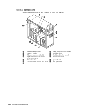
Internal components To open the computer cover, see "Opening the cover" on page 94. 1 Power-supply assembly 8 Power switch and LED assembly 2 Memory modules 9 Hard disk drive 3 Microprocessor heat sinks (2) 10 Hard disk drive fan assembly 4 Optical drives (such as a CD or 11 Microprocessors (2) DVD drive) 3 bays 5 Internal speaker 12 System board 6 3.5 inch diskette drive or card reader 13 Rear system fan 7 Front USB and audio connectors 128 Hardware Maintenance Manual
Internal components To open the computer cover, see "Opening the cover" on page 94. 1 Power-supply assembly 8 Power switch and LED assembly 2 Memory modules 9 Hard disk drive 3 Microprocessor heat sinks (2) 10 Hard disk drive fan assembly 4 Optical drives (such as a CD or 11 Microprocessors (2) DVD drive) 3 bays 5 Internal speaker 12 System board 6 3.5 inch diskette drive or card reader 13 Rear system fan 7 Front USB and audio connectors 128 Hardware Maintenance Manual


