User Manual
Page 5
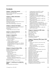
... tests 45 Viewing the test log 47 Chapter 6. General information . . . . 39 The ThinkVantage Productivity Center program . . 39 Additional information resources 39 Specifications 40 Types (6423, 6427, 6483, and 6493 40 Chapter 4. Replacing FRUs (types 6423 and 6483 89 Locations 90 Controls and connectors on the front of the computer 90 Connectors... module 117 Replacing a fan assembly 119 Replacing the internal speaker 120 Replacing the front panel connector assembly . . 121 Completing the FRU replacement 123 © Copyright Lenovo 2006, 2008 iii
... tests 45 Viewing the test log 47 Chapter 6. General information . . . . 39 The ThinkVantage Productivity Center program . . 39 Additional information resources 39 Specifications 40 Types (6423, 6427, 6483, and 6493 40 Chapter 4. Replacing FRUs (types 6423 and 6483 89 Locations 90 Controls and connectors on the front of the computer 90 Connectors... module 117 Replacing a fan assembly 119 Replacing the internal speaker 120 Replacing the front panel connector assembly . . 121 Completing the FRU replacement 123 © Copyright Lenovo 2006, 2008 iii
User Manual
Page 6
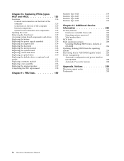
FRU lists 159 Machine Type 6423 159 Machine Type 6427 175 Machine Type 6483 192 Machine Type 6493 215 Chapter 12. Additional Service Information 235 Security features 235 Hardware controlled Passwords 235 Operating system password ... a POST/BIOS update failure . . 236 Power management 238 Automatic configuration and power interface (ACPI) BIOS 238 Automatic Power-On features 238 Appendix. Replacing FRUs (types 6427 and 6493 125 Locations 126 Controls and connectors on the front of the computer 126 Connectors on the rear of the computer . . . 127 Internal components...
FRU lists 159 Machine Type 6423 159 Machine Type 6427 175 Machine Type 6483 192 Machine Type 6493 215 Chapter 12. Additional Service Information 235 Security features 235 Hardware controlled Passwords 235 Operating system password ... a POST/BIOS update failure . . 236 Power management 238 Automatic configuration and power interface (ACPI) BIOS 238 Automatic Power-On features 238 Appendix. Replacing FRUs (types 6427 and 6493 125 Locations 126 Controls and connectors on the front of the computer 126 Connectors on the rear of the computer . . . 127 Internal components...

User Manual
Page 46
... 6493 when rack mounted: Width: 427 mm (16.8 in.) Height: 210 mm (8 in.) Depth: 579 mm (22.8 in.) Weight machine type 6427 and 6493: Maximum configuration: 26.00 kg (57 lbs) Environment Air temperature: Operating at 0 - 3000 ft (914.4 m): 10° to 35... voltage: Range 100 V - 240 V Input kilovolt-amperes (kVA) (approximate) Minimum configuration as shipped: 0.17 kVA Maximum configuration: 0.8 kVA Electrical input machine types 6427 and 6493 Input voltage: Range 100 V - 240 V Input kilovolt-amperes (kVA) (approximate) Minimum configuration as shipped: 0.17 kVA Maximum configuration: 1.2 kVA 40 ...
... 6493 when rack mounted: Width: 427 mm (16.8 in.) Height: 210 mm (8 in.) Depth: 579 mm (22.8 in.) Weight machine type 6427 and 6493: Maximum configuration: 26.00 kg (57 lbs) Environment Air temperature: Operating at 0 - 3000 ft (914.4 m): 10° to 35... voltage: Range 100 V - 240 V Input kilovolt-amperes (kVA) (approximate) Minimum configuration as shipped: 0.17 kVA Maximum configuration: 0.8 kVA Electrical input machine types 6427 and 6493 Input voltage: Range 100 V - 240 V Input kilovolt-amperes (kVA) (approximate) Minimum configuration as shipped: 0.17 kVA Maximum configuration: 1.2 kVA 40 ...

User Manual
Page 131
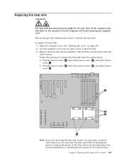
Chapter 10. Replacing FRUs (types 6427 and 6493) Important Before you work safely. Only the major FRUs are to be done by trained service technicians only. These precautions and guidelines will help you replace any FRU, read Chapter 2, "Safety information," on page 3. This chapter does not contain a remove and replace procedure for all FRUs. FRU replacements are documented. © Copyright Lenovo 2006, 2008 125
Chapter 10. Replacing FRUs (types 6427 and 6493) Important Before you work safely. Only the major FRUs are to be done by trained service technicians only. These precautions and guidelines will help you replace any FRU, read Chapter 2, "Safety information," on page 3. This chapter does not contain a remove and replace procedure for all FRUs. FRU replacements are documented. © Copyright Lenovo 2006, 2008 125

User Manual
Page 133
Replacing FRUs (types 6427 and 6493) 127 Connectors on the rear of the computer Some connectors on the rear of your computer are color-coded to help you determine ...
Replacing FRUs (types 6427 and 6493) 127 Connectors on the rear of the computer Some connectors on the rear of your computer are color-coded to help you determine ...

User Manual
Page 135
Replacing FRUs (types 6427 and 6493) 129 System board connectors and components 1 Memory slots (8) 13 Auxiliary USB connector 2 2 24 Pin power connector 14 IEEE 1394 Connector 3 10 Pin power ...
Replacing FRUs (types 6427 and 6493) 129 System board connectors and components 1 Memory slots (8) 13 Auxiliary USB connector 2 2 24 Pin power connector 14 IEEE 1394 Connector 3 10 Pin power ...

User Manual
Page 137
Secure the cover using your locking device. Chapter 10. Replacing FRUs (types 6427 and 6493) 131 Align the cover with the chassis. 2. Close the cover. 3. Check to be sure the cover is latched. 5. To replace the cover: 1. Engage the cover latch. 4.
Secure the cover using your locking device. Chapter 10. Replacing FRUs (types 6427 and 6493) 131 Align the cover with the chassis. 2. Close the cover. 3. Check to be sure the cover is latched. 5. To replace the cover: 1. Engage the cover latch. 4.

User Manual
Page 139
... card" on the adapter cards. Take note of the location of the slot. See "System board connectors and components" on page 130. 2. Replacing FRUs (types 6427 and 6493) 133 See "Opening the cover" on page 129. 5. Open the computer cover. Chapter 10. Remove the card retaining screw, if one is a tight...
... card" on the adapter cards. Take note of the location of the slot. See "System board connectors and components" on page 130. 2. Replacing FRUs (types 6427 and 6493) 133 See "Opening the cover" on page 129. 5. Open the computer cover. Chapter 10. Remove the card retaining screw, if one is a tight...

User Manual
Page 141
...-lingual translations)" on the computer. Refer to "Completing the FRU replacement" on page 129. 5. Access the system board. Remove the old battery. 6. Replacing FRUs (types 6427 and 6493) 135 See "System board connectors and components" on page 158. The battery normally requires no battery lasts forever. This is normal after battery...
...-lingual translations)" on the computer. Refer to "Completing the FRU replacement" on page 129. 5. Access the system board. Remove the old battery. 6. Replacing FRUs (types 6427 and 6493) 135 See "System board connectors and components" on page 158. The battery normally requires no battery lasts forever. This is normal after battery...

User Manual
Page 143
Replacing FRUs (types 6427 and 6493) 137 7. Slide the power-supply assembly toward the front of the computer, remove it from the chassis. Chapter 10. Remove the power supply retaining screws located inside the computer chassis. 8.
Replacing FRUs (types 6427 and 6493) 137 7. Slide the power-supply assembly toward the front of the computer, remove it from the chassis. Chapter 10. Remove the power supply retaining screws located inside the computer chassis. 8.

User Manual
Page 145
... card. 5. Push the retention feature toward the front of the slot. Note: The card is removed from the card slot. Chapter 10. Replacing FRUs (types 6427 and 6493) 139 Replacing an adapter card 1.
... card. 5. Push the retention feature toward the front of the slot. Note: The card is removed from the card slot. Chapter 10. Replacing FRUs (types 6427 and 6493) 139 Replacing an adapter card 1.
User Manual
Page 147
... 2 , then fully remove screw 4 , and fully remove screw 2 . Replacing the heat sink CAUTION: The heat sink and microprocessor might be very hot. Replacing FRUs (types 6427 and 6493) 141 Turn off the computer and wait three to five minutes to touch the heat Chapter 10. Lay the computer on the heat...
... 2 , then fully remove screw 4 , and fully remove screw 2 . Replacing the heat sink CAUTION: The heat sink and microprocessor might be very hot. Replacing FRUs (types 6427 and 6493) 141 Turn off the computer and wait three to five minutes to touch the heat Chapter 10. Lay the computer on the heat...

User Manual
Page 149
... heat sink from the system board, lift the small handle 1 and open the retainer 2 . Important Touch only the sides of the socket. Replacing FRUs (types 6427 and 6493) 143 See "Replacing the heat sink" on its right side to help make the system board more accessible. 3. Turn off the computer and...
... heat sink from the system board, lift the small handle 1 and open the retainer 2 . Important Touch only the sides of the socket. Replacing FRUs (types 6427 and 6493) 143 See "Replacing the heat sink" on its right side to help make the system board more accessible. 3. Turn off the computer and...

User Manual
Page 151
... of pliers to the system board. 3. Remove the hard disk drive fan. Remove any adapter cards installed in the figure: 7. Chapter 10. Replacing FRUs (types 6427 and 6493) 145 Open the computer cover. Note: The latches for easier access to unlatch the connectors. 5. Replacing the system board This section provides instructions...
... of pliers to the system board. 3. Remove the hard disk drive fan. Remove any adapter cards installed in the figure: 7. Chapter 10. Replacing FRUs (types 6427 and 6493) 145 Open the computer cover. Note: The latches for easier access to unlatch the connectors. 5. Replacing the system board This section provides instructions...

User Manual
Page 153
Connect all cables to "Completing the FRU replacement" on page 129. 20. Replacing FRUs (types 6427 and 6493) 147 See the system board illustration for your machine type at "System board connectors and components" on page 158. Chapter 10. Go to the system board. 19.
Connect all cables to "Completing the FRU replacement" on page 129. 20. Replacing FRUs (types 6427 and 6493) 147 See the system board illustration for your machine type at "System board connectors and components" on page 158. Chapter 10. Go to the system board. 19.

User Manual
Page 155
Install the hard disk drive and bracket into the drive bay. 7. Connect the signal and power cables to "Completing the FRU replacement" on page 158. Replacing FRUs (types 6427 and 6493) 149 Go to the rear of the new hard disk drive. 8. Chapter 10. 6.
Install the hard disk drive and bracket into the drive bay. 7. Connect the signal and power cables to "Completing the FRU replacement" on page 158. Replacing FRUs (types 6427 and 6493) 149 Go to the rear of the new hard disk drive. 8. Chapter 10. 6.

User Manual
Page 157
... from the rear of the drive or card reader cables. Connect the flat cable to replace the diskette drive or card reader. 1. Replacing FRUs (types 6427 and 6493) 151 Disconnect the drive or card reader cables from the chassis. 5. Chapter 10. See "Opening the cover" on page 129. 3. See "System board...
... from the rear of the drive or card reader cables. Connect the flat cable to replace the diskette drive or card reader. 1. Replacing FRUs (types 6427 and 6493) 151 Disconnect the drive or card reader cables from the chassis. 5. Chapter 10. See "Opening the cover" on page 129. 3. See "System board...

User Manual
Page 159
... DIMMs in the following guidelines: v Install the DIMMs in identical pairs, which means the DIMMs of two DIMMs in the figure below: 1. Replacing FRUs (types 6427 and 6493) 153 When installing or replacing memory modules, use the following order, as shown in one pair can differ from another pair. v DIMM Slot...
... DIMMs in the following guidelines: v Install the DIMMs in identical pairs, which means the DIMMs of two DIMMs in the figure below: 1. Replacing FRUs (types 6427 and 6493) 153 When installing or replacing memory modules, use the following order, as shown in one pair can differ from another pair. v DIMM Slot...

User Manual
Page 161
6. Chapter 10. Replacing FRUs (types 6427 and 6493) 155 Go to "Completing the FRU replacement" on page 158.
6. Chapter 10. Replacing FRUs (types 6427 and 6493) 155 Go to "Completing the FRU replacement" on page 158.

User Manual
Page 163
... the metal speaker slots and then push the internal speaker downward until the speaker-locking tabs snap into position. 8. Go to remove. 6. Replacing FRUs (types 6427 and 6493) 157 Connect the speaker cable to replace the internal speaker. 1. Chapter 10. Note the location of the internal-speaker cable connection. Remove the...
... the metal speaker slots and then push the internal speaker downward until the speaker-locking tabs snap into position. 8. Go to remove. 6. Replacing FRUs (types 6427 and 6493) 157 Connect the speaker cable to replace the internal speaker. 1. Chapter 10. Note the location of the internal-speaker cable connection. Remove the...