Hardware Maintenance Manual
Page 1
Hardware Maintenance Manual ThinkPad T400s, T410s, and T410si
Hardware Maintenance Manual ThinkPad T400s, T410s, and T410si
Hardware Maintenance Manual
Page 3
... supporting the Lenovo diagnostics programs 33 Power system checkout 35 Checking the AC adapter 35 Checking operational charging 36 Checking the battery pack 36 Checking the backup battery 37 Chapter 4. Status indicators . . . . . 55 Chapter 6. Contents About this manual iii Chapter... . . . . 80 1120 Keyboard bezel and speaker assembly . . . 81 © Copyright Lenovo 2009, 2012 i Fn key combinations . . . 59 Chapter 7. Removing and replacing a FRU 65 Before servicing ThinkPad T400s, T410s, and T410si 65 1010 Battery pack 66 1020 Serial Ultrabay Slim device or travel bezel . ...
... supporting the Lenovo diagnostics programs 33 Power system checkout 35 Checking the AC adapter 35 Checking operational charging 36 Checking the battery pack 36 Checking the backup battery 37 Chapter 4. Status indicators . . . . . 55 Chapter 6. Contents About this manual iii Chapter... . . . . 80 1120 Keyboard bezel and speaker assembly . . . 81 © Copyright Lenovo 2009, 2012 i Fn key combinations . . . 59 Chapter 7. Removing and replacing a FRU 65 Before servicing ThinkPad T400s, T410s, and T410si 65 1010 Battery pack 66 1020 Serial Ultrabay Slim device or travel bezel . ...
Hardware Maintenance Manual
Page 5
ThinkPad T400s ThinkPad T410s and T410si MT 2801, 2808, 2809, 2815, 2823, 2824, and 2825 MT 2901, 2904, 2907, 2912, 2924, 2926, and 2928 Use this manual along with ThinkPad products. Use this manual This manual contains service and reference information for trained service technicians who... problems effectively.Before servicing a ThinkPad product, be sure to read all the information under Chapter 1 "Safety information" on page 1 and Chapter 2 "Important service information" on page 23. © Copyright Lenovo 2009, 2012 iii About this manual along with the advanced diagnostic ...
ThinkPad T400s ThinkPad T410s and T410si MT 2801, 2808, 2809, 2815, 2823, 2824, and 2825 MT 2901, 2904, 2907, 2912, 2924, 2926, and 2928 Use this manual along with ThinkPad products. Use this manual This manual contains service and reference information for trained service technicians who... problems effectively.Before servicing a ThinkPad product, be sure to read all the information under Chapter 1 "Safety information" on page 1 and Chapter 2 "Important service information" on page 23. © Copyright Lenovo 2009, 2012 iii About this manual along with the advanced diagnostic ...
Hardware Maintenance Manual
Page 72
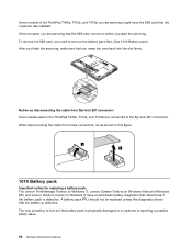
...Lenovo Solution Center (in the ThinkPad T400s, T410s, and T410si are servicing has the SIM card, remove it before you start the servicing. A battery pack FRU should not be replaced unless this is if the battery pack is physically damaged or a customer is reporting a possible safety issue. 66 Hardware Maintenance Manual... Some models of the ThinkPad T400s, T410s, and T410si you are servicing might have an automatic battery diagnostic that determines if the battery pack ...
...Lenovo Solution Center (in the ThinkPad T400s, T410s, and T410si are servicing has the SIM card, remove it before you start the servicing. A battery pack FRU should not be replaced unless this is if the battery pack is physically damaged or a customer is reporting a possible safety issue. 66 Hardware Maintenance Manual... Some models of the ThinkPad T400s, T410s, and T410si you are servicing might have an automatic battery diagnostic that determines if the battery pack ...
Hardware Maintenance Manual
Page 76
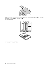
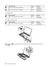
For ThinkPad T400s: b a 3 4 3 For ThinkPad T410s and T410si: 70 Hardware Maintenance Manual 2 Note: For ThinkPad T400s, if only one DIMM is used on the computer you are servicing, the card must be installed in SLOT-0 ( a ), but not in SLOT-1 ( b ).
For ThinkPad T400s: b a 3 4 3 For ThinkPad T410s and T410si: 70 Hardware Maintenance Manual 2 Note: For ThinkPad T400s, if only one DIMM is used on the computer you are servicing, the card must be installed in SLOT-0 ( a ), but not in SLOT-1 ( b ).
Hardware Maintenance Manual
Page 78
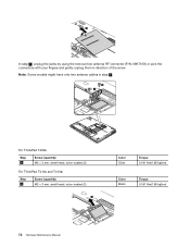
2 In step 3 , unplug the jacks by using the removal tool antenna RF connector (P/N: 08K7159) or pick the connectors with your fingers and gently unplug them in step 3 . 4 4 3 For ThinkPad T400s Step 4 Screw (quantity) M2 × 3 mm, small-head, nylon-coated (2) For ThinkPad T410s and T410si Step 4 Screw (quantity) M2 × 3 mm, small-head, nylon-coated (2) 5 Color Silver Torque 0.181 Nm(1.85 kgfcm) Color Black Torque 0.181 Nm(1.85 kgfcm) 72 Hardware Maintenance Manual Note: Some models might have only two antenna cables in direction of the arrow.
2 In step 3 , unplug the jacks by using the removal tool antenna RF connector (P/N: 08K7159) or pick the connectors with your fingers and gently unplug them in step 3 . 4 4 3 For ThinkPad T400s Step 4 Screw (quantity) M2 × 3 mm, small-head, nylon-coated (2) For ThinkPad T410s and T410si Step 4 Screw (quantity) M2 × 3 mm, small-head, nylon-coated (2) 5 Color Silver Torque 0.181 Nm(1.85 kgfcm) Color Black Torque 0.181 Nm(1.85 kgfcm) 72 Hardware Maintenance Manual Note: Some models might have only two antenna cables in direction of the arrow.
Hardware Maintenance Manual
Page 80
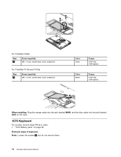
4 4 3 For ThinkPad T400s Step 4 Screw (quantity) M2 × 3 mm, small-head, nylon-coated (2) For ThinkPad T410s and T410si Step 4 Screw (quantity) M2 × 3 mm, small-head, nylon-coated (2) Color Silver Torque 0.181 Nm (1.85 kgfcm) Color Black Torque 0.181 Nm (1.... in order: • "1010 Battery pack" on page 66 Removal steps of keyboard Note: Loosen the screws 1 , but do not remove them. 74 Hardware Maintenance Manual
4 4 3 For ThinkPad T400s Step 4 Screw (quantity) M2 × 3 mm, small-head, nylon-coated (2) For ThinkPad T410s and T410si Step 4 Screw (quantity) M2 × 3 mm, small-head, nylon-coated (2) Color Silver Torque 0.181 Nm (1.85 kgfcm) Color Black Torque 0.181 Nm (1.... in order: • "1010 Battery pack" on page 66 Removal steps of keyboard Note: Loosen the screws 1 , but do not remove them. 74 Hardware Maintenance Manual
Hardware Maintenance Manual
Page 88
Step 2 3 Screw (quantity) M2 × 6 mm, bind-head, nylon-coated (3) M2 × 4 mm, bind-head, nylon-coated (2) For ThinkPad T400s Step 4 Screw (quantity) M2 × 3 mm, small-head, nylon-coated (1) For ThinkPad T410s and T410si Step 4 Screw (quantity) M2 × 3 mm, small-head, nylon-coated (1) 6 Color Black Black Torque 0.181 Nm (1.85 kgfcm) 0.181... kgfcm) 5 Note: Before step 8 , pull the cables out from the cable guide hole of the keyboard bezel as shown in the figure a . a 8 7 82 Hardware Maintenance Manual
Step 2 3 Screw (quantity) M2 × 6 mm, bind-head, nylon-coated (3) M2 × 4 mm, bind-head, nylon-coated (2) For ThinkPad T400s Step 4 Screw (quantity) M2 × 3 mm, small-head, nylon-coated (1) For ThinkPad T410s and T410si Step 4 Screw (quantity) M2 × 3 mm, small-head, nylon-coated (1) 6 Color Black Black Torque 0.181 Nm (1.85 kgfcm) 0.181... kgfcm) 5 Note: Before step 8 , pull the cables out from the cable guide hole of the keyboard bezel as shown in the figure a . a 8 7 82 Hardware Maintenance Manual

Hardware Maintenance Manual
Page 94
...PC-Doctor for DOS, after replacing the system board, run PC-Doctor for the HDD Active Protection System™ a 88 Hardware Maintenance Manual Place the computer on the top side of the system board are extremely sensitive. When you put it only on a padded surface such ...: Do not apply physical shock to put a system board down, be sure not to make sure that the HDD Active Protection System still functions. For ThinkPad T400s: a : ICH (I/O Controller Hub) b : CPU c : GMCH (Graphics Memory Controller Hub) d : Accelerometer chip for DOS to drop or stack the system board. &#...
...PC-Doctor for DOS, after replacing the system board, run PC-Doctor for the HDD Active Protection System™ a 88 Hardware Maintenance Manual Place the computer on the top side of the system board are extremely sensitive. When you put it only on a padded surface such ...: Do not apply physical shock to put a system board down, be sure not to make sure that the HDD Active Protection System still functions. For ThinkPad T400s: a : ICH (I/O Controller Hub) b : CPU c : GMCH (Graphics Memory Controller Hub) d : Accelerometer chip for DOS to drop or stack the system board. &#...
Hardware Maintenance Manual
Page 102
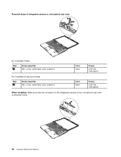
Removal steps of integrated camera or microphone sub card 4 1 2 3 For ThinkPad T400s Step 1 Screw (quantity) M2 × 3 mm, small-head, nylon-coated (1) Color Silver Torque 0.181 Nm (1.85 kgfcm) For ThinkPad T410s and T410si Step 1 Screw (quantity) M2 × 3 mm, small-head, nylon-coated (1) Color Black Torque 0.181 Nm (1.85 kgfcm) When installing: Make sure that the connector of the integrated camera or the microphone sub card is attached firmly. 6 5 96 Hardware Maintenance Manual
Removal steps of integrated camera or microphone sub card 4 1 2 3 For ThinkPad T400s Step 1 Screw (quantity) M2 × 3 mm, small-head, nylon-coated (1) Color Silver Torque 0.181 Nm (1.85 kgfcm) For ThinkPad T410s and T410si Step 1 Screw (quantity) M2 × 3 mm, small-head, nylon-coated (1) Color Black Torque 0.181 Nm (1.85 kgfcm) When installing: Make sure that the connector of the integrated camera or the microphone sub card is attached firmly. 6 5 96 Hardware Maintenance Manual
(Simplified Chinese) Service and Troubleshooting Guide
Page 76
8. %w7(# (fE"yw nBDu}ywQO+= Web >c#*TdxPND,kCJ http:// www.lenovo.com/think/support,%w Troubleshooting,;s%w User's guides and manuals# 70 ThinkPad T400s ,$kJOoO8O
8. %w7(# (fE"yw nBDu}ywQO+= Web >c#*TdxPND,kCJ http:// www.lenovo.com/think/support,%w Troubleshooting,;s%w User's guides and manuals# 70 ThinkPad T400s ,$kJOoO8O
(Greek) Service and Troubleshooting Guide
Page 94
Regulatory Notice Lenovo http://www.lenovo.com/think/support Troubleshooting User's guides and manuals″. 86 ThinkPad T400s 2 Hardware and Sound Device Manager). 3 Network adapters). 4 Properties 5 Power Management). 6 Allow this device to wake the computer). 7 OK. Στα Windows XP: 1 Start Control panel). 2 Performance and Maintenance) → System). 3 Hardware Device Manager). 4 Network adapters). 5 Properties 6 Power Management). 7 Allow this device to bring the computer out of standby). 8 OK.
Regulatory Notice Lenovo http://www.lenovo.com/think/support Troubleshooting User's guides and manuals″. 86 ThinkPad T400s 2 Hardware and Sound Device Manager). 3 Network adapters). 4 Properties 5 Power Management). 6 Allow this device to wake the computer). 7 OK. Στα Windows XP: 1 Start Control panel). 2 Performance and Maintenance) → System). 3 Hardware Device Manager). 4 Network adapters). 5 Properties 6 Power Management). 7 Allow this device to bring the computer out of standby). 8 OK.


