(English) Hardware Password Manager Deployment Guide
Page 39
...and disable Hardware Password Manager • ThinkPad - Chapter 6. Only the HDPs remain set. Add a hard disk drive When a hard disk is replaced, the POP, SVP, hardware account, and server credentials no longer be retrieved using a Lenovo supplied Hardware Password Manager DOS utility. The...clear the HDP, you must enter it manually. Removing the CMOS battery will inform the user that the system board is moved from the ThinkManagement Console. You must be retrieved using a Lenovo-supplied Hardware Password Manager DOS utility. Renew Hardware Account will clear ...
...and disable Hardware Password Manager • ThinkPad - Chapter 6. Only the HDPs remain set. Add a hard disk drive When a hard disk is replaced, the POP, SVP, hardware account, and server credentials no longer be retrieved using a Lenovo supplied Hardware Password Manager DOS utility. The...clear the HDP, you must enter it manually. Removing the CMOS battery will inform the user that the system board is moved from the ThinkManagement Console. You must be retrieved using a Lenovo-supplied Hardware Password Manager DOS utility. Renew Hardware Account will clear ...

Hardware Maintenance Manual
Page 5
... 58 How to remove the hard-disk password . . . . 59 Power management 60 Screen blank mode 60 Sleep (Standby) mode 60 Hibernation mode 61 © Copyright Lenovo 2008, 2011 Symptom-to-FRU index 62 Numeric error codes 62 Error messages 66 Beep symptoms 67 No-beep symptoms 67 LCD-related symptoms 68... the serial number of the system unit 80 Retaining the UUID 80 Reading or writing the ECA information . . . 81 Removing and replacing a FRU . . . . 83 1010 Battery pack 84 1020 Serial Ultrabay Slim device or Serial Ultrabay Enhanced device 85 1030 Hard disk drive (HDD) cover, HDD, and HDD...
... 58 How to remove the hard-disk password . . . . 59 Power management 60 Screen blank mode 60 Sleep (Standby) mode 60 Hibernation mode 61 © Copyright Lenovo 2008, 2011 Symptom-to-FRU index 62 Numeric error codes 62 Error messages 66 Beep symptoms 67 No-beep symptoms 67 LCD-related symptoms 68... the serial number of the system unit 80 Retaining the UUID 80 Reading or writing the ECA information . . . 81 Removing and replacing a FRU . . . . 83 1010 Battery pack 84 1020 Serial Ultrabay Slim device or Serial Ultrabay Enhanced device 85 1030 Hard disk drive (HDD) cover, HDD, and HDD...

Hardware Maintenance Manual
Page 16
... it into fire or water, or short-circuit it . Use only the battery in the appropriate parts listing when replacing the battery pack. Do not disassemble it, throw it into your eyes or on after washing. 8 ThinkPad T400 and R400 Hardware Maintenance Manual Use only the battery in the appropriate parts listing. Use of an incorrect...
... it into fire or water, or short-circuit it . Use only the battery in the appropriate parts listing when replacing the battery pack. Do not disassemble it, throw it into your eyes or on after washing. 8 ThinkPad T400 and R400 Hardware Maintenance Manual Use only the battery in the appropriate parts listing. Use of an incorrect...

Hardware Maintenance Manual
Page 17
Safety information 9 DANGER Unless hot swap is allowed for the FRU being replaced, do not remove the plastic cover that protects the lower part of the inverter card. DANGER Though the main batteries have low voltage, a shorted or grounded battery can produce enough current to burn personnel or combustible materials. DANGER To avoid shock, do as follows before removing it: power off the computer, unplug all power cords from electrical outlets, remove the battery pack, and disconnect any interconnecting cables.
Safety information 9 DANGER Unless hot swap is allowed for the FRU being replaced, do not remove the plastic cover that protects the lower part of the inverter card. DANGER Though the main batteries have low voltage, a shorted or grounded battery can produce enough current to burn personnel or combustible materials. DANGER To avoid shock, do as follows before removing it: power off the computer, unplug all power cords from electrical outlets, remove the battery pack, and disconnect any interconnecting cables.
Hardware Maintenance Manual
Page 58
... 1. Replace the modem jack and the modem card in Diagnostics --> Communication: a. Turn on the computer. 3. Press enter. 5. If the docking station or the port replicator is running. Place the computer on the computer. Diagnostics --> Systemboard --> Keyboard 2. Power Diagnostics --> ThinkPad Devices --> AC Adapter, Battery 1 .... Using cursor keys, select HDD diagnostic program. Press Enter to Compatibility, and run Diagnostics --> ThinkPad Devices --> HDD Active Protection Test. Interactive Tests --> Diskette 50 ThinkPad T400 and R400 Hardware Maintenance Manual
... 1. Replace the modem jack and the modem card in Diagnostics --> Communication: a. Turn on the computer. 3. Press enter. 5. If the docking station or the port replicator is running. Place the computer on the computer. Diagnostics --> Systemboard --> Keyboard 2. Power Diagnostics --> ThinkPad Devices --> AC Adapter, Battery 1 .... Using cursor keys, select HDD diagnostic program. Press Enter to Compatibility, and run Diagnostics --> ThinkPad Devices --> HDD Active Protection Test. Interactive Tests --> Diskette 50 ThinkPad T400 and R400 Hardware Maintenance Manual
Hardware Maintenance Manual
Page 60
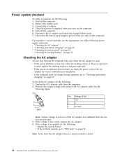
..."Checking the battery pack" on page 53 v "Checking the backup battery" on the computer. 5. v If the computer does not charge during operation, go to "Checking operational charging" on page 50. Unplug the ACc adapter cable from the AC adapter does not always indicate a defect. 52 ThinkPad T400 and R400 ... 54 Checking the AC adapter You are servicing. 3. Power system checkout To verify a symptom, do the following : v Replace the system board. Check that the battery pack supplies power when you turn on , check the power cord of the AC adapter for correct continuity and installation. If...
..."Checking the battery pack" on page 53 v "Checking the backup battery" on the computer. 5. v If the computer does not charge during operation, go to "Checking operational charging" on page 50. Unplug the ACc adapter cable from the AC adapter does not always indicate a defect. 52 ThinkPad T400 and R400 ... 54 Checking the AC adapter You are servicing. 3. Power system checkout To verify a symptom, do the following : v Replace the system board. Check that the battery pack supplies power when you turn on , check the power cord of the AC adapter for correct continuity and installation. If...

Hardware Maintenance Manual
Page 61
.... If the charge indicator or icon still does not turn on , replace the battery pack. To check your battery, move your cursor to 30 K . To get detailed information about the battery, double-click the Power Manager Battery Gauge icon. Power off the computer. 2. If the voltage is less... cools down, reinstall and recharge it is still not charged, go to 100% of battery power remaining is more than +11.0 V dc after recharging, replace the battery. 4. Remove the battery pack and measure the voltage between battery terminals 5 and 7. If the voltage is still less than +11.0 V dc, ...
.... If the charge indicator or icon still does not turn on , replace the battery pack. To check your battery, move your cursor to 30 K . To get detailed information about the battery, double-click the Power Manager Battery Gauge icon. Power off the computer. 2. If the voltage is less... cools down, reinstall and recharge it is still not charged, go to 100% of battery power remaining is more than +11.0 V dc after recharging, replace the battery. 4. Remove the battery pack and measure the voltage between battery terminals 5 and 7. If the voltage is still less than +11.0 V dc, ...

Hardware Maintenance Manual
Page 62
... the ac adapter from it. 2. Remove the battery pack (see "1060 Backup battery" on page 84). 4. v If the backup battery discharges quickly after replacement, replace the system board. 54 ThinkPad T400 and R400 Hardware Maintenance Manual Measure the voltage of the backup battery. See the following : 1. v If the voltage is correct, replace the system board. Turn the computer upside...
... the ac adapter from it. 2. Remove the battery pack (see "1060 Backup battery" on page 84). 4. v If the backup battery discharges quickly after replacement, replace the system board. 54 ThinkPad T400 and R400 Hardware Maintenance Manual Measure the voltage of the backup battery. See the following : 1. v If the voltage is correct, replace the system board. Turn the computer upside...
Hardware Maintenance Manual
Page 66
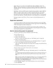
...battery pack. Turn on the screen; Note: There are servicing supports the Passphrase function, enter the BIOS Setup Utility and go to enter BIOS Setup Utility. If no master HDP is known by the service technician: 1. Turn on page 84. 3. For the other models, enter the POP. Select Password. 58 ThinkPad T400...User mode requires two HDPs; The user must be replaced for access to the BIOS Setup Utility and change the system configuration. Select Security, using the cursor directional keys to remove the backup battery, see "1010 Battery pack" on the computer and wait until the ...
...battery pack. Turn on the screen; Note: There are servicing supports the Passphrase function, enter the BIOS Setup Utility and go to enter BIOS Setup Utility. If no master HDP is known by the service technician: 1. Turn on page 84. 3. For the other models, enter the POP. Select Password. 58 ThinkPad T400...User mode requires two HDPs; The user must be replaced for access to the BIOS Setup Utility and change the system configuration. Select Security, using the cursor directional keys to remove the backup battery, see "1010 Battery pack" on the computer and wait until the ...

Hardware Maintenance Manual
Page 72
...:xx Failed. 1. Load Setup Defaults in -Turn off and remove the miniPCI network card. 1. Replace the backup battery. 3. System board. 1802 Unauthorized network card is set in -Turn off and remove the daughter card. 2. System board. 64 ThinkPad T400 and R400 Hardware Maintenance Manual System board. 02F6 Software NMI failed 1. Numeric error codes (continued...
...:xx Failed. 1. Load Setup Defaults in -Turn off and remove the miniPCI network card. 1. Replace the backup battery. 3. System board. 1802 Unauthorized network card is set in -Turn off and remove the daughter card. 2. System board. 64 ThinkPad T400 and R400 Hardware Maintenance Manual System board. 02F6 Software NMI failed 1. Numeric error codes (continued...

Hardware Maintenance Manual
Page 77
...a. Devices attached to the docking station or the port replicator c. If the problem remains, replace the following FRUs one at a time (do not isolate FRUs that all of the following : 1. Battery pack e. DIMM h. Verify that the power supply being used at least 10 times. 2.... Remove or disconnect all attached devices are installed, or if the system simply is detected, replace the FRU shown by the computer. Non-ThinkPad devices b. External diskette drive...
...a. Devices attached to the docking station or the port replicator c. If the problem remains, replace the following FRUs one at a time (do not isolate FRUs that all of the following : 1. Battery pack e. DIMM h. Verify that the power supply being used at least 10 times. 2.... Remove or disconnect all attached devices are installed, or if the system simply is detected, replace the FRU shown by the computer. Non-ThinkPad devices b. External diskette drive...

Hardware Maintenance Manual
Page 91
... until you have made sure that all power cords from electrical outlets, remove the battery pack, and then disconnect any FRUs that pertain to be damaged by the numbers in the drawing. 7. Before replacing any FRU, turn it in the direction as given by shaking the computer gently ... "Locations" on page 79. 3. Before touching it in the direction as given by using an electrostatic discharge (ESD) strap (P/N 6405959). © Copyright Lenovo 2008, 2009 83 Follow the correct sequence in the steps for removing the FRU, as shown in the drawing. 6. Be sure to , and can cause...
... until you have made sure that all power cords from electrical outlets, remove the battery pack, and then disconnect any FRUs that pertain to be damaged by the numbers in the drawing. 7. Before replacing any FRU, turn it in the direction as given by shaking the computer gently ... "Locations" on page 79. 3. Before touching it in the direction as given by using an electrostatic discharge (ESD) strap (P/N 6405959). © Copyright Lenovo 2008, 2009 83 Follow the correct sequence in the steps for removing the FRU, as shown in the drawing. 6. Be sure to , and can cause...

Hardware Maintenance Manual
Page 92
... automatic battery diagnostic that the battery is non-warranty replacement. Then make sure that a physically damaged battery pack is defective. Removal steps of the slot. DANGER Use only the battery specified in the parts list for replacing a battery pack: ThinkVantage Toolbox (in Windows 7) and Lenovo System Toolbox (in the locked position. 84 ThinkPad T400 and R400 Hardware Maintenance Manual A battery pack...
... automatic battery diagnostic that the battery is non-warranty replacement. Then make sure that a physically damaged battery pack is defective. Removal steps of the slot. DANGER Use only the battery specified in the parts list for replacing a battery pack: ThinkVantage Toolbox (in Windows 7) and Lenovo System Toolbox (in the locked position. 84 ThinkPad T400 and R400 Hardware Maintenance Manual A battery pack...

Hardware Maintenance Manual
Page 93
... to release the device from the bay. 1 2 3 Removing and replacing a FRU 85 Removal steps of the following devices: v Ultrabay Plus devices v Ultrabay 2000 devices Table 10. 1020 Serial Ultrabay Slim device or Serial Ultrabay Enhanced device For access, remove this FRU: v "1010 Battery pack" on page 84 Note: Serial Ultrabay Slim does...
... to release the device from the bay. 1 2 3 Removing and replacing a FRU 85 Removal steps of the following devices: v Ultrabay Plus devices v Ultrabay 2000 devices Table 10. 1020 Serial Ultrabay Slim device or Serial Ultrabay Enhanced device For access, remove this FRU: v "1010 Battery pack" on page 84 Note: Serial Ultrabay Slim does...

Hardware Maintenance Manual
Page 96
If the fingerprint reader has any defects, you can replace it by the procedures given in order: v "1010 Battery pack" on page 84 Note: In models with or without a fingerprint reader. Table 12. Removal steps of palm rest 1 1 1 1 For T400 Step Icon 1 For R400 Step Icon 1 Screw (quantity) M2 &#...) M2 × 17 mm, flat-head, nylon-coated (4) Color Black Torque 0.167 Nm (1.7 kgfcm) Color Black Torque 0.167 Nm (1.7 kgfcm) 88 ThinkPad T400 and R400 Hardware Maintenance Manual 1040 Palm rest or palm rest with fingerprint reader For access, remove this FRU in this section, which are the...
If the fingerprint reader has any defects, you can replace it by the procedures given in order: v "1010 Battery pack" on page 84 Note: In models with or without a fingerprint reader. Table 12. Removal steps of palm rest 1 1 1 1 For T400 Step Icon 1 For R400 Step Icon 1 Screw (quantity) M2 &#...) M2 × 17 mm, flat-head, nylon-coated (4) Color Black Torque 0.167 Nm (1.7 kgfcm) Color Black Torque 0.167 Nm (1.7 kgfcm) 88 ThinkPad T400 and R400 Hardware Maintenance Manual 1040 Palm rest or palm rest with fingerprint reader For access, remove this FRU in this section, which are the...

Hardware Maintenance Manual
Page 99
1050 DIMM For access, remove these FRUs in the slot and does not move easily. Removal steps of dimm Note: If only one DIMM is firmly fixed in order: v "1010 Battery pack" on page 84 v "1040 Palm rest or palm rest with fingerprint reader" on the computer you are servicing, the card must be installed in SLOT-0 ( a ), but not in SLOT-1 ( b ). 1 b 2 a 1 When installing: Insert the notched end of the DIMM into the place. Make sure that it snaps into the socket. Press the DIMM firmly, and pivot it until it is used on page 88 Table 13. Removing and replacing a FRU 91
1050 DIMM For access, remove these FRUs in the slot and does not move easily. Removal steps of dimm Note: If only one DIMM is firmly fixed in order: v "1010 Battery pack" on page 84 v "1040 Palm rest or palm rest with fingerprint reader" on the computer you are servicing, the card must be installed in SLOT-0 ( a ), but not in SLOT-1 ( b ). 1 b 2 a 1 When installing: Insert the notched end of the DIMM into the place. Make sure that it snaps into the socket. Press the DIMM firmly, and pivot it until it is used on page 88 Table 13. Removing and replacing a FRU 91

Hardware Maintenance Manual
Page 101
Removal steps of keyboard 1 For T400 Step Icon 1 For R400 Step Icon 1 Screw (quantity) M2 × 14 mm, flat-head, nylon-coated (1) Screw (quantity) M2 × 17 mm, flat-head, nylon-coated (1) Color Black Torque 0.167 Nm (1.7 kgfcm) Color Black Torque 0.167 Nm (1.7 kgfcm) Lift the keyboard a little in order: v "1010 Battery pack" on page 84 v "1040 Palm rest or palm rest with fingerprint reader" on page 88 Table 15. 1070 Keyboard For access, remove these FRUs in the direction shown by arrow 2 , and then detach the connector 3 . 2 3 Removing and replacing a FRU 93
Removal steps of keyboard 1 For T400 Step Icon 1 For R400 Step Icon 1 Screw (quantity) M2 × 14 mm, flat-head, nylon-coated (1) Screw (quantity) M2 × 17 mm, flat-head, nylon-coated (1) Color Black Torque 0.167 Nm (1.7 kgfcm) Color Black Torque 0.167 Nm (1.7 kgfcm) Lift the keyboard a little in order: v "1010 Battery pack" on page 84 v "1040 Palm rest or palm rest with fingerprint reader" on page 88 Table 15. 1070 Keyboard For access, remove these FRUs in the direction shown by arrow 2 , and then detach the connector 3 . 2 3 Removing and replacing a FRU 93

Hardware Maintenance Manual
Page 103
... daughter card because the modem function is on page 93 Table 16. 1080 Modem daughter card (MDC-3.0) For access, remove these FRUs in order: v "1010 Battery pack" on page 84 v "1040 Palm rest or palm rest with your fingers in the direction shown by pulling the tab with fingerprint reader" on... 1 Screw (quantity) M2 × 3 mm, small-head, nylon-coated (2) Color Silver Torque 0.167 Nm (1.7 kgfcm) In step 2 , remove the card by the arrow. Removing and replacing a FRU 95
... daughter card because the modem function is on page 93 Table 16. 1080 Modem daughter card (MDC-3.0) For access, remove these FRUs in order: v "1010 Battery pack" on page 84 v "1040 Palm rest or palm rest with your fingers in the direction shown by pulling the tab with fingerprint reader" on... 1 Screw (quantity) M2 × 3 mm, small-head, nylon-coated (2) Color Silver Torque 0.167 Nm (1.7 kgfcm) In step 2 , remove the card by the arrow. Removing and replacing a FRU 95

Hardware Maintenance Manual
Page 105
Note: Some models might have two antenna cables in order: v "1010 Battery pack" on page 93 Table 17. 1090 PCI Express Mini Card for wireless LAN/WiMAX Full size PCI Express Mini Card: In step 1 , unplug the ... For access, remove these FRUs in step 1 . 2 2 1 Step 2 Screw (quantity) M2 × 3 mm, small-head, nylon-coated (2) Color Silver Torque 0.167 Nm (1.7 kgfcm) Removing and replacing a FRU 97
Note: Some models might have two antenna cables in order: v "1010 Battery pack" on page 93 Table 17. 1090 PCI Express Mini Card for wireless LAN/WiMAX Full size PCI Express Mini Card: In step 1 , unplug the ... For access, remove these FRUs in step 1 . 2 2 1 Step 2 Screw (quantity) M2 × 3 mm, small-head, nylon-coated (2) Color Silver Torque 0.167 Nm (1.7 kgfcm) Removing and replacing a FRU 97

Hardware Maintenance Manual
Page 113
Table 20. Removing and replacing a FRU 105 Removal steps of SIM card slot (continued) Remove the SIM card from the battery pack slot in the direction of arrow 3 as shown in this figure. 2 3 Step 2 Screw (quantity) M2 × 3.5 mm, flat-head, nylon-coated (1) Color Black Torque 0.167 Nm (1.7 kgfcm) When installing: Make sure the connector 3 is attached firmly.
Table 20. Removing and replacing a FRU 105 Removal steps of SIM card slot (continued) Remove the SIM card from the battery pack slot in the direction of arrow 3 as shown in this figure. 2 3 Step 2 Screw (quantity) M2 × 3.5 mm, flat-head, nylon-coated (1) Color Black Torque 0.167 Nm (1.7 kgfcm) When installing: Make sure the connector 3 is attached firmly.


