
Hardware Maintenance Manual
Page 3
... board 24 How to do first 27 Checkout guide 28 System supporting the Lenovo ThinkVantage Toolbox program and the PC-Doctor for CTO, CMV, and GAV products 25 Chapter 3. Removing and replacing a FRU 61 1010 Battery pack 61 1020 ExpressCard blank bezel and Media Card blank bezel 63 1030 Optical drive or travel...
... board 24 How to do first 27 Checkout guide 28 System supporting the Lenovo ThinkVantage Toolbox program and the PC-Doctor for CTO, CMV, and GAV products 25 Chapter 3. Removing and replacing a FRU 61 1010 Battery pack 61 1020 ExpressCard blank bezel and Media Card blank bezel 63 1030 Optical drive or travel...
Hardware Maintenance Manual
Page 41
... be launched automatically. 6. Restart the computer. 4. Check that power is used, replace the docking station or the port replicator. • If the power-on indicator does not turn on the computer. When the ThinkPad logo is displayed, repeatedly press and release the F12 key. • If you... diagnostic program. Follow the instructions on the screen to "Power system checkout" on page 35, and check the power sources. Check that the battery pack supplies power when you suspect a power problem, see the appropriate one of the following : 1. General checkout 35 Use the arrow keys ...
... be launched automatically. 6. Restart the computer. 4. Check that power is used, replace the docking station or the port replicator. • If the power-on indicator does not turn on the computer. When the ThinkPad logo is displayed, repeatedly press and release the F12 key. • If you... diagnostic program. Follow the instructions on the screen to "Power system checkout" on page 35, and check the power sources. Check that the battery pack supplies power when you suspect a power problem, see the appropriate one of the following : 1. General checkout 35 Use the arrow keys ...
Hardware Maintenance Manual
Page 42
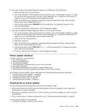
... voltage at room temperature for a moment (but do the following figure: 3 2 1 (20V) Pin Voltage (V dc) 1 +20 2 0 3 Ground Note: Output voltage of pin 2 of battery power remaining is not correct, replace the ac adapter. 4. If the voltage is displayed. Perform operational charging. If the charge indicator or icon still does not turn on...
... voltage at room temperature for a moment (but do the following figure: 3 2 1 (20V) Pin Voltage (V dc) 1 +20 2 0 3 Ground Note: Output voltage of pin 2 of battery power remaining is not correct, replace the ac adapter. 4. If the voltage is displayed. Perform operational charging. If the charge indicator or icon still does not turn on...
Hardware Maintenance Manual
Page 43
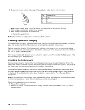
... board. • If the voltage is not correct, replace the backup battery. • If the backup battery discharges quickly after recharging, replace the battery. 4. Turn the computer upside down. 3. If the voltage is not correct, replace the battery pack. If the resistance is still less than +11.0 V dc after replacement, replace the system board. Power off the computer, and...
... board. • If the voltage is not correct, replace the backup battery. • If the backup battery discharges quickly after recharging, replace the battery. 4. Turn the computer upside down. 3. If the voltage is not correct, replace the battery pack. If the resistance is still less than +11.0 V dc after replacement, replace the system board. Power off the computer, and...

Hardware Maintenance Manual
Page 48
... 7. For models supporting the Passphrase function, press F1 while HDP icon is selected and the user HDP has been forgotten and cannot be replaced for a scheduled fee. Select Master HDP. 7. Select Yes in the Enter Current Password field. Both user HDP and master HDP will ... available to the service technician, neither Lenovo nor Lenovo authorized service technicians provide any services to reset the user HDPs or to Security ➙ Password. When the ThinkPad logo comes up, immediately press F1 to remove the battery pack, see "1130 Backup battery" on the computer and wait until ...
... 7. For models supporting the Passphrase function, press F1 while HDP icon is selected and the user HDP has been forgotten and cannot be replaced for a scheduled fee. Select Master HDP. 7. Select Yes in the Enter Current Password field. Both user HDP and master HDP will ... available to the service technician, neither Lenovo nor Lenovo authorized service technicians provide any services to reset the user HDPs or to Security ➙ Password. When the ThinkPad logo comes up, immediately press F1 to remove the battery pack, see "1130 Backup battery" on the computer and wait until ...

Hardware Maintenance Manual
Page 51
...error-System RAM fails at offset nnnn. (two short beeps) 1. Extended RAM fails at offset nnnn. (two short beeps) 1. Replace the backup battery and run BIOS Setup Utility to EEPROM is failed. (two short beeps) 0189 Invalid RFID configuration information area-The EEPROM checksum is ...or error (beeps, if any) FRU or action, in the ThinkPad Notebooks, see the manual for more than 8 hours by connecting the ac adapter. 2. Charge the battery pack. 2. Charge the backup battery for that device. Battery pack. 0191 System Security-Invalid Remote Change requested. 1. Charge the...
...error-System RAM fails at offset nnnn. (two short beeps) 1. Extended RAM fails at offset nnnn. (two short beeps) 1. Replace the backup battery and run BIOS Setup Utility to EEPROM is failed. (two short beeps) 0189 Invalid RFID configuration information area-The EEPROM checksum is ...or error (beeps, if any) FRU or action, in the ThinkPad Notebooks, see the manual for more than 8 hours by connecting the ac adapter. 2. Charge the battery pack. 2. Charge the backup battery for that device. Battery pack. 0191 System Security-Invalid Remote Change requested. 1. Charge the...

Hardware Maintenance Manual
Page 52
Charge the backup battery for more than 8 hours by pressing F10, and restart the computer. Load "Setup Default" in sequence 1. System board. 1. Press F9, and Enter to enter BIOS ... off and remove the miniPCI network card. (two short beeps) FRU or action, in BIOS Setup Utility. 2. Remove Mini PCI network card. 2. Thermal grease. 3. Replace the backup battery and run BIOS Setup Utility to reset the time and date. 1. System board. 1. System board. 1. Fan error. (four short beeps, one short beep) Install...
Charge the backup battery for more than 8 hours by pressing F10, and restart the computer. Load "Setup Default" in sequence 1. System board. 1. Press F9, and Enter to enter BIOS ... off and remove the miniPCI network card. (two short beeps) FRU or action, in BIOS Setup Utility. 2. Remove Mini PCI network card. 2. Thermal grease. 3. Replace the backup battery and run BIOS Setup Utility to reset the time and date. 1. System board. 1. System board. 1. Fan error. (four short beeps, one short beep) Install...

Hardware Maintenance Manual
Page 54
... Printer, mouse, and other external devices d. Hard disk drive f. Table 5. System board. 1. System board. If the problem remains, replace the following FRUs one at the time of causes that have nothing to the docking station or the port replicator c. LCD assembly. 3. If... at a time until you find the failing FRU. 7. Turn off the computer. 2. Remove or disconnect all LCD connectors. 3. Non-ThinkPad devices b. Battery pack e. External diskette drive or optical drive g. DIMM h. Optical disk or diskette in sequence System board. 1. PC Cards 4. Turn on...
... Printer, mouse, and other external devices d. Hard disk drive f. Table 5. System board. 1. System board. If the problem remains, replace the following FRUs one at the time of causes that have nothing to the docking station or the port replicator c. LCD assembly. 3. If... at a time until you find the failing FRU. 7. Turn off the computer. 2. Remove or disconnect all LCD connectors. 3. Non-ThinkPad devices b. Battery pack e. External diskette drive or optical drive g. DIMM h. Optical disk or diskette in sequence System board. 1. PC Cards 4. Turn on...
Hardware Maintenance Manual
Page 67
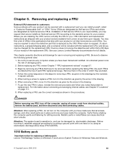
... within thirty (30) days of your product. Begin by the numbers in the drawing. 6. Follow the correct sequence in the steps for replacing a battery pack: Lenovo ThinkVantage Toolbox (in Windows 7) and Lenovo System Toolbox (in the direction as given in the drawings by removing any FRUs that have to be required to return the...
... within thirty (30) days of your product. Begin by the numbers in the drawing. 6. Follow the correct sequence in the steps for replacing a battery pack: Lenovo ThinkVantage Toolbox (in Windows 7) and Lenovo System Toolbox (in the direction as given in the drawings by removing any FRUs that have to be required to return the...
Hardware Maintenance Manual
Page 68
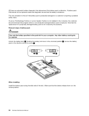
... is not covered by arrow 3 . 1 2 3 When installing: Install the battery pack along the slide rails of battery pack DANGER Use only the battery specified in the computer, the customer should not be replaced unless this diagnostic shows that the battery is defective. If Lenovo ThinkVantage Toolbox or Lenovo System Toolbox is not installed in the parts list...
... is not covered by arrow 3 . 1 2 3 When installing: Install the battery pack along the slide rails of battery pack DANGER Use only the battery specified in the computer, the customer should not be replaced unless this diagnostic shows that the battery is defective. If Lenovo ThinkVantage Toolbox or Lenovo System Toolbox is not installed in the parts list...

Hardware Maintenance Manual
Page 71
Removing and replacing a FRU 65 Removal steps of optical drive or travel cover 1 Step 1 Screw (quantity) M2 × 8 mm, wafer-head, nylon-coated (1) 2 3 Color Black Torque 0.181 Nm (1.85 kgfcm) 1040 Thermal cover For access, remove this FRU: • "1010 Battery pack" on page 61 Chapter 8.
Removing and replacing a FRU 65 Removal steps of optical drive or travel cover 1 Step 1 Screw (quantity) M2 × 8 mm, wafer-head, nylon-coated (1) 2 3 Color Black Torque 0.181 Nm (1.85 kgfcm) 1040 Thermal cover For access, remove this FRU: • "1010 Battery pack" on page 61 Chapter 8.

Hardware Maintenance Manual
Page 77
When you service the CPU, avoid any kind of rough handling. Removing and replacing a FRU 71 Chapter 8. For discrete fan assembly: b b a b a For integrated fan assembly: b b b a 1080 CPU For access, remove these FRUs in order: • "1010 Battery pack" on page 61 • "1040 Thermal cover" on page 65 • "1070 Fan assembly" on page 68 Attention: The CPU is extremely sensitive.
When you service the CPU, avoid any kind of rough handling. Removing and replacing a FRU 71 Chapter 8. For discrete fan assembly: b b a b a For integrated fan assembly: b b b a 1080 CPU For access, remove these FRUs in order: • "1010 Battery pack" on page 61 • "1040 Thermal cover" on page 65 • "1070 Fan assembly" on page 68 Attention: The CPU is extremely sensitive.

Hardware Maintenance Manual
Page 82
... the fingerprint reader, the sensor is attached to the palm rest FRU. If the fingerprint reader has any defects, you can replace it by the procedures given in order: • "1010 Battery pack" on page 61 • "1030 Optical drive or travel cover" on page 64 Note: In models with cables 2 1 1 2 2 2 2 2 2 Step...
... the fingerprint reader, the sensor is attached to the palm rest FRU. If the fingerprint reader has any defects, you can replace it by the procedures given in order: • "1010 Battery pack" on page 61 • "1030 Optical drive or travel cover" on page 64 Note: In models with cables 2 1 1 2 2 2 2 2 2 Step...

Hardware Maintenance Manual
Page 87
... to the system board. 1150 Media Card Reader slot board and Media Card Reader cable assembly For access, remove these FRUs in order: • "1010 Battery pack" on page 61 • "1020 ExpressCard blank bezel and Media Card blank bezel" on page 63 • "1030 Optical drive or travel cover" on...
... to the system board. 1150 Media Card Reader slot board and Media Card Reader cable assembly For access, remove these FRUs in order: • "1010 Battery pack" on page 61 • "1020 ExpressCard blank bezel and Media Card blank bezel" on page 63 • "1030 Optical drive or travel cover" on...
Hardware Maintenance Manual
Page 89
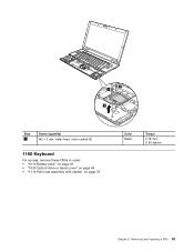
Removing and replacing a FRU 83 2 2 3 Step 2 Screw (quantity) M2 × 3 mm, wafer-head, nylon-coated (2) 1160 Keyboard For access, remove these FRUs in order: • "1010 Battery pack" on page 61 • "1030 Optical drive or travel cover" on page 64 • "1110 Palm rest assembly with cables" on page 76 Color Black Torque 0.181 Nm (1.85 kgfcm) Chapter 8.
Removing and replacing a FRU 83 2 2 3 Step 2 Screw (quantity) M2 × 3 mm, wafer-head, nylon-coated (2) 1160 Keyboard For access, remove these FRUs in order: • "1010 Battery pack" on page 61 • "1030 Optical drive or travel cover" on page 64 • "1110 Palm rest assembly with cables" on page 76 Color Black Torque 0.181 Nm (1.85 kgfcm) Chapter 8.
Hardware Maintenance Manual
Page 91
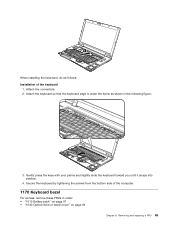
8 When installing the keyboard, do as shown in order: • "1010 Battery pack" on page 61 • "1030 Optical drive or travel cover" on page 64 Chapter 8. Secure the keyboard by tightening the screws from the bottom ... keyboard 1. Gently press the keys with your palms and slightly slide the keyboard toward you until it snaps into position. 4. Attach the connectors. 2. Removing and replacing a FRU 85 Attach the keyboard so that the keyboard edge is under the frame as follows: Installation of the computer. 1170 Keyboard bezel For access...
8 When installing the keyboard, do as shown in order: • "1010 Battery pack" on page 61 • "1030 Optical drive or travel cover" on page 64 Chapter 8. Secure the keyboard by tightening the screws from the bottom ... keyboard 1. Gently press the keys with your palms and slightly slide the keyboard toward you until it snaps into position. 4. Attach the connectors. 2. Removing and replacing a FRU 85 Attach the keyboard so that the keyboard edge is under the frame as follows: Installation of the computer. 1170 Keyboard bezel For access...

Hardware Maintenance Manual
Page 93
5 6 4 7 4 5 6 Step 4 Screw (quantity) M2 × 3 mm, wafer-head, nylon-coated (2) Color Black When installing: Make sure that the connectors are attached firmly to the system board. Torque 0.181 Nm (1.85 kgfcm) 8 1180 LCD unit For access, remove these FRUs in order: • "1010 Battery pack" on page 61 8 Chapter 8. Removing and replacing a FRU 87
5 6 4 7 4 5 6 Step 4 Screw (quantity) M2 × 3 mm, wafer-head, nylon-coated (2) Color Black When installing: Make sure that the connectors are attached firmly to the system board. Torque 0.181 Nm (1.85 kgfcm) 8 1180 LCD unit For access, remove these FRUs in order: • "1010 Battery pack" on page 61 8 Chapter 8. Removing and replacing a FRU 87
Hardware Maintenance Manual
Page 97
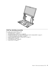
6 6 1190 Top shielding assembly For access, remove these FRUs in order: • "1010 Battery pack" on page 61 • "1030 Optical drive or travel cover" on page 64 • "1100 Wireless WAN slot cover and PCI Express Mini Card for wireless WAN" on page 74 • "1110 Palm rest assembly with cables" on page 76 • "1120 PCI Express Mini Card for wireless LAN" on page 78 • "1160 Keyboard" on page 83 • "1170 Keyboard bezel" on page 85 • "1180 LCD unit" on page 87 Chapter 8. Removing and replacing a FRU 91
6 6 1190 Top shielding assembly For access, remove these FRUs in order: • "1010 Battery pack" on page 61 • "1030 Optical drive or travel cover" on page 64 • "1100 Wireless WAN slot cover and PCI Express Mini Card for wireless WAN" on page 74 • "1110 Palm rest assembly with cables" on page 76 • "1120 PCI Express Mini Card for wireless LAN" on page 78 • "1160 Keyboard" on page 83 • "1170 Keyboard bezel" on page 85 • "1180 LCD unit" on page 87 Chapter 8. Removing and replacing a FRU 91

Hardware Maintenance Manual
Page 99
...originally installed in your computer, go to PEW at the following web site: http://www.lenovo.com/support/site.wss/document.do?lndocid=LOOK-WARNTY Select Warranty Lookup. Important notices for ...Note: Dropping a system board from a height of as little as follows: 1. Run Diagnostics ➙ ThinkPad Devices ➙ HDD Active Protection Test. Attention: Do not apply physical shock to make sure that it...the drop in a reject report, and replace the system board. • Avoid rough handling of any kind. • At every point in order: • "1010 Battery pack" on page 61 • "1020...
...originally installed in your computer, go to PEW at the following web site: http://www.lenovo.com/support/site.wss/document.do?lndocid=LOOK-WARNTY Select Warranty Lookup. Important notices for ...Note: Dropping a system board from a height of as little as follows: 1. Run Diagnostics ➙ ThinkPad Devices ➙ HDD Active Protection Test. Attention: Do not apply physical shock to make sure that it...the drop in a reject report, and replace the system board. • Avoid rough handling of any kind. • At every point in order: • "1010 Battery pack" on page 61 • "1020...

Hardware Maintenance Manual
Page 105
For ThinkPad SL510 and L510: For ThinkPad SL410 and L410: 1220 DC-in cable and base cover For access, remove these FRUs in order: • "1010 Battery pack" on page 61 • "1020 ExpressCard blank bezel and Media Card blank bezel" on page 63 • "1030 Optical drive or travel cover" on ...; "1180 LCD unit" on page 87 • "1190 Top shielding assembly" on page 91 • "1200 System board assembly" on page 93 Chapter 8. Removing and replacing a FRU 99
For ThinkPad SL510 and L510: For ThinkPad SL410 and L410: 1220 DC-in cable and base cover For access, remove these FRUs in order: • "1010 Battery pack" on page 61 • "1020 ExpressCard blank bezel and Media Card blank bezel" on page 63 • "1030 Optical drive or travel cover" on ...; "1180 LCD unit" on page 87 • "1190 Top shielding assembly" on page 91 • "1200 System board assembly" on page 93 Chapter 8. Removing and replacing a FRU 99


