Hardware Maintenance Manual
Page 5
Contents About this manual v Safety information 1 General safety 2 Electrical safety 3 Safety inspection guide 5 Handling devices that are sensitive to electrostatic discharge 6 Grounding requirements 6 Safety notices: multilingual translations . . . . . ...index 39 Numeric error codes 39 Error messages 44 Beep symptoms 45 © Copyright Lenovo 2008, 2009 No-beep symptoms 45 LCD-related symptoms 46 Intermittent problems 47 Undetermined problems 47 ThinkPad SL400, SL400c, SL500, and SL500c 49 Specifications 49 Status indicators 52 FRU tests 54 Fn key combinations 56 FRU ...
Contents About this manual v Safety information 1 General safety 2 Electrical safety 3 Safety inspection guide 5 Handling devices that are sensitive to electrostatic discharge 6 Grounding requirements 6 Safety notices: multilingual translations . . . . . ...index 39 Numeric error codes 39 Error messages 44 Beep symptoms 45 © Copyright Lenovo 2008, 2009 No-beep symptoms 45 LCD-related symptoms 46 Intermittent problems 47 Undetermined problems 47 ThinkPad SL400, SL400c, SL500, and SL500c 49 Specifications 49 Status indicators 52 FRU tests 54 Fn key combinations 56 FRU ...

Hardware Maintenance Manual
Page 6
... LAN antenna assembly, wireless WAN antenna assembly, and camera cable (for ThinkPad SL500 and 500c) . . 145 Parts list 146 Overall 147 LCD FRUs 190 Keyboard 214 Miscellaneous parts 215 AC adapters 216 Power cords 217 Recovery discs 218 Common service tools 228 Notices 229 Trademarks 230 iv ThinkPad SL400, SL400c, SL500, and SL500c Hardware Maintenance Manual
... LAN antenna assembly, wireless WAN antenna assembly, and camera cable (for ThinkPad SL500 and 500c) . . 145 Parts list 146 Overall 147 LCD FRUs 190 Keyboard 214 Miscellaneous parts 215 AC adapters 216 Power cords 217 Recovery discs 218 Common service tools 228 Notices 229 Trademarks 230 iv ThinkPad SL400, SL400c, SL500, and SL500c Hardware Maintenance Manual

Hardware Maintenance Manual
Page 7
... to troubleshoot problems effectively. ThinkPad SL400 MT 2743 ThinkPad SL400c MT 4413 ThinkPad SL500 MT 2746 ThinkPad SL500c MT 4414 Use this manual along with the advanced diagnostic tests to read all the information under "Safety information" on page 1 and "Important service information" on page 17. © Copyright Lenovo 2008, 2009 v About this manual This manual contains service and reference...
... to troubleshoot problems effectively. ThinkPad SL400 MT 2743 ThinkPad SL400c MT 4413 ThinkPad SL500 MT 2746 ThinkPad SL500c MT 4414 Use this manual along with the advanced diagnostic tests to read all the information under "Safety information" on page 1 and "Important service information" on page 17. © Copyright Lenovo 2008, 2009 v About this manual This manual contains service and reference...
Hardware Maintenance Manual
Page 76
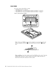
1060 DIMM For access, remove these FRUs in the slot and does not move easily. 68 ThinkPad SL400, SL400c, SL500, and SL500c Hardware Maintenance Manual Press the DIMM firmly, and pivot it until it is used on page 67 Table 16. b a When installing: Insert the notched end of DIMM 1 1 2 Note: ...
1060 DIMM For access, remove these FRUs in the slot and does not move easily. 68 ThinkPad SL400, SL400c, SL500, and SL500c Hardware Maintenance Manual Press the DIMM firmly, and pivot it until it is used on page 67 Table 16. b a When installing: Insert the notched end of DIMM 1 1 2 Note: ...
Hardware Maintenance Manual
Page 82
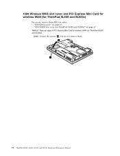
1090 Wireless WAN slot cover and PCI Express Mini Card for wireless WAN (for ThinkPad SL500 and SL500c) For access, remove these FRUs in order: v "1010 Battery pack" on page 67 Table 20. Removal steps of PCI Express Mini Card for wireless WAN (for ThinkPad SL500 and SL500c)" on page 63 v "1050 DIMM slot cover (for ThinkPad SL500 and SL500c) Note: Loosen the screws 1 , but do not remove them. 2 1 74 ThinkPad SL400, SL400c, SL500, and SL500c Hardware Maintenance Manual
1090 Wireless WAN slot cover and PCI Express Mini Card for wireless WAN (for ThinkPad SL500 and SL500c) For access, remove these FRUs in order: v "1010 Battery pack" on page 67 Table 20. Removal steps of PCI Express Mini Card for wireless WAN (for ThinkPad SL500 and SL500c)" on page 63 v "1050 DIMM slot cover (for ThinkPad SL500 and SL500c) Note: Loosen the screws 1 , but do not remove them. 2 1 74 ThinkPad SL400, SL400c, SL500, and SL500c Hardware Maintenance Manual
Hardware Maintenance Manual
Page 86
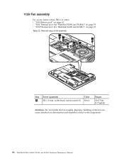
Removal steps of the fan can cause distortion or deformation and imperfect contact with components. 78 ThinkPad SL400, SL400c, SL500, and SL500c Hardware Maintenance Manual Improper handling of fan assembly 2 2 2 2 1 2 Step 2 Screw (quantity) M2 × 4 mm, wafer-head, nylon-coated (5) Color Silver Torque 0.167 Nm (1.7 kgfcm) Attention:...fan roughly. 1120 Fan assembly For access, remove these FRUs in order: v "1010 Battery pack" on page 63 v "1100 Thermal door (for ThinkPad SL400 and SL400c)" on page 76 v "1110 Thermal door (for ThinkPad SL500 and SL500c)" on page 77 Table 23.
Removal steps of the fan can cause distortion or deformation and imperfect contact with components. 78 ThinkPad SL400, SL400c, SL500, and SL500c Hardware Maintenance Manual Improper handling of fan assembly 2 2 2 2 1 2 Step 2 Screw (quantity) M2 × 4 mm, wafer-head, nylon-coated (5) Color Silver Torque 0.167 Nm (1.7 kgfcm) Attention:...fan roughly. 1120 Fan assembly For access, remove these FRUs in order: v "1010 Battery pack" on page 63 v "1100 Thermal door (for ThinkPad SL400 and SL400c)" on page 76 v "1110 Thermal door (for ThinkPad SL500 and SL500c)" on page 77 Table 23.
Hardware Maintenance Manual
Page 94
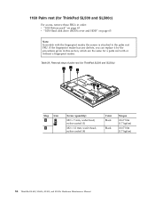
... reader. Table 29. 1160 Palm rest (for ThinkPad SL500 and SL500c) For access, remove these FRUs in this section, which are the same for ThinkPad SL500 and SL500c) 2 1 2 21 Step 1 Icon 2 Screw... (quantity) M2 × 7 mm, wafer-head, nylon-coated (1) M2 × 12 mm, wafer-head, nylon-coated (4) Color Black Black Torque 0.167 Nm (1.7 kgfcm) 0.167 Nm (1.7 kgfcm) 86 ThinkPad SL400, SL400c, SL500, and SL500c Hardware Maintenance Manual...
... reader. Table 29. 1160 Palm rest (for ThinkPad SL500 and SL500c) For access, remove these FRUs in this section, which are the same for ThinkPad SL500 and SL500c) 2 1 2 21 Step 1 Icon 2 Screw... (quantity) M2 × 7 mm, wafer-head, nylon-coated (1) M2 × 12 mm, wafer-head, nylon-coated (4) Color Black Black Torque 0.167 Nm (1.7 kgfcm) 0.167 Nm (1.7 kgfcm) 86 ThinkPad SL400, SL400c, SL500, and SL500c Hardware Maintenance Manual...
Hardware Maintenance Manual
Page 96
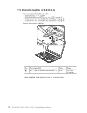
Removal steps of BDC-2.1 1 2 Step 1 Screw (quantity) M2 × 3 mm, wafer-head, nylon-coated (1) Color Black Torque 0.167 Nm (1.7 kgfcm) When installing: Make sure that connector is attached firmly. 88 ThinkPad SL400, SL400c, SL500, and SL500c Hardware Maintenance Manual 1170 Bluetooth daughter card (BDC-2.1) For access, remove these FRUs in order: v "1010 Battery pack" on page 63 v "1030 Hard disk drive (HDD) cover and HDD" on page 65 v "1150 Palm rest (for ThinkPad SL400 and SL400c)" on page 84 v "1160 Palm rest (for ThinkPad SL500 and SL500c)" on page 86 Table 30.
Removal steps of BDC-2.1 1 2 Step 1 Screw (quantity) M2 × 3 mm, wafer-head, nylon-coated (1) Color Black Torque 0.167 Nm (1.7 kgfcm) When installing: Make sure that connector is attached firmly. 88 ThinkPad SL400, SL400c, SL500, and SL500c Hardware Maintenance Manual 1170 Bluetooth daughter card (BDC-2.1) For access, remove these FRUs in order: v "1010 Battery pack" on page 63 v "1030 Hard disk drive (HDD) cover and HDD" on page 65 v "1150 Palm rest (for ThinkPad SL400 and SL400c)" on page 84 v "1160 Palm rest (for ThinkPad SL500 and SL500c)" on page 86 Table 30.
Hardware Maintenance Manual
Page 100
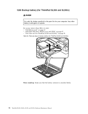
... ThinkPad SL500 and SL500c)" on page 86 Table 33. Any other battery could ignite or explode. Removal steps of backup battery (for your computer. For access, remove these FRUs in the parts list for ThinkPad SL500 and SL500c) 2 12 2 1 When installing: Make sure that the battery connector is attached firmly. 92 ThinkPad SL400, SL400c, SL500, and SL500c Hardware Maintenance Manual...
... ThinkPad SL500 and SL500c)" on page 86 Table 33. Any other battery could ignite or explode. Removal steps of backup battery (for your computer. For access, remove these FRUs in the parts list for ThinkPad SL500 and SL500c) 2 12 2 1 When installing: Make sure that the battery connector is attached firmly. 92 ThinkPad SL400, SL400c, SL500, and SL500c Hardware Maintenance Manual...
Hardware Maintenance Manual
Page 106
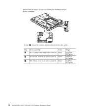
Removal steps of top case sub assembly (for ThinkPad SL500 and SL500c) (continued) 5 3 5 4 In step 2 , release the wireless antenna cables from the cable guide. Table 36. Step 3 Screw (quantity) Color M2 × 12 mm, wafer-head, nylon-coated (1) Black 4 M2 × 4 mm, wafer-head, nylon-coated (1) Silver 5 M2 × 7 mm, wafer-head, nylon-coated (2) Black Torque 0.167 Nm (1.7 kgfcm) 0.167 Nm (1.7 kgfcm) 0.167 Nm (1.7 kgfcm) 98 ThinkPad SL400, SL400c, SL500, and SL500c Hardware Maintenance Manual
Removal steps of top case sub assembly (for ThinkPad SL500 and SL500c) (continued) 5 3 5 4 In step 2 , release the wireless antenna cables from the cable guide. Table 36. Step 3 Screw (quantity) Color M2 × 12 mm, wafer-head, nylon-coated (1) Black 4 M2 × 4 mm, wafer-head, nylon-coated (1) Silver 5 M2 × 7 mm, wafer-head, nylon-coated (2) Black Torque 0.167 Nm (1.7 kgfcm) 0.167 Nm (1.7 kgfcm) 0.167 Nm (1.7 kgfcm) 98 ThinkPad SL400, SL400c, SL500, and SL500c Hardware Maintenance Manual

Hardware Maintenance Manual
Page 114
Table 38. Removal steps of LCD unit (for ThinkPad SL500 and SL500c) (continued) 3 3 Step 3 Screw (quantity) M2 × 3 mm, wafer-head, nylon-coated (2) Color Black Torque 0.167 Nm (1.7 kgfcm) 106 ThinkPad SL400, SL400c, SL500, and SL500c Hardware Maintenance Manual
Table 38. Removal steps of LCD unit (for ThinkPad SL500 and SL500c) (continued) 3 3 Step 3 Screw (quantity) M2 × 3 mm, wafer-head, nylon-coated (2) Color Black Torque 0.167 Nm (1.7 kgfcm) 106 ThinkPad SL400, SL400c, SL500, and SL500c Hardware Maintenance Manual

Hardware Maintenance Manual
Page 116
As you route the cables, make sure that the LCD connector is attached firmly. 108 ThinkPad SL400, SL400c, SL500, and SL500c Hardware Maintenance Manual Table 38. Route the antenna cables along the cable guides and secure them with the tapes. Make sure that they are not subjected to be broken. 2. Tension could cause the cables to be damaged by the cable guides, or a wire to any tension. Removal steps of LCD unit (for ThinkPad SL500 and SL500c) (continued) 7 8 8 When installing: 1.
As you route the cables, make sure that the LCD connector is attached firmly. 108 ThinkPad SL400, SL400c, SL500, and SL500c Hardware Maintenance Manual Table 38. Route the antenna cables along the cable guides and secure them with the tapes. Make sure that they are not subjected to be broken. 2. Tension could cause the cables to be damaged by the cable guides, or a wire to any tension. Removal steps of LCD unit (for ThinkPad SL500 and SL500c) (continued) 7 8 8 When installing: 1.

Hardware Maintenance Manual
Page 118
Step Screw (quantity) Color Torque 2 M2 × 3 mm, wafer-head, nylon-coated (2) Black 0.167 Nm (1.7 kgfcm) 3 M2 × 5 mm, wafer-head, nylon-coated (1) Black 0.167 Nm (1.7 kgfcm) 4 110 ThinkPad SL400, SL400c, SL500, and SL500c Hardware Maintenance Manual Table 39. For the other models, skip the step 3. Removal steps of Frame L (continued) 2 3 2 Note: Step 3 is only for ThinkPad SL500.
Step Screw (quantity) Color Torque 2 M2 × 3 mm, wafer-head, nylon-coated (2) Black 0.167 Nm (1.7 kgfcm) 3 M2 × 5 mm, wafer-head, nylon-coated (1) Black 0.167 Nm (1.7 kgfcm) 4 110 ThinkPad SL400, SL400c, SL500, and SL500c Hardware Maintenance Manual Table 39. For the other models, skip the step 3. Removal steps of Frame L (continued) 2 3 2 Note: Step 3 is only for ThinkPad SL500.

Hardware Maintenance Manual
Page 130
... v "1260 Frame L (magnesium frame assembly)" on page 109 v "1270 SATA-ODD connector board (for ThinkPad SL500 and SL500c) 1 1 1 1 Step 1 Screw (quantity) M2 × 3 mm, wafer-head, nylon-coated (4) Color Black Torque 0.167 Nm (1.7 kgfcm) 122 ThinkPad SL400, SL400c, SL500, and SL500c Hardware Maintenance Manual Removal steps of Frame R, I/O board, I /O board FPC, DC-in connector, small board, and...
... v "1260 Frame L (magnesium frame assembly)" on page 109 v "1270 SATA-ODD connector board (for ThinkPad SL500 and SL500c) 1 1 1 1 Step 1 Screw (quantity) M2 × 3 mm, wafer-head, nylon-coated (4) Color Black Torque 0.167 Nm (1.7 kgfcm) 122 ThinkPad SL400, SL400c, SL500, and SL500c Hardware Maintenance Manual Removal steps of Frame R, I/O board, I /O board FPC, DC-in connector, small board, and...

Hardware Maintenance Manual
Page 132
Removal steps of Frame R, I/O board, I/O board FPC, DC-in connector, small board, and base cover (for ThinkPad SL500 and SL500c) (continued) 7 8 10 9 9 12 11 124 ThinkPad SL400, SL400c, SL500, and SL500c Hardware Maintenance Manual Table 45.
Removal steps of Frame R, I/O board, I/O board FPC, DC-in connector, small board, and base cover (for ThinkPad SL500 and SL500c) (continued) 7 8 10 9 9 12 11 124 ThinkPad SL400, SL400c, SL500, and SL500c Hardware Maintenance Manual Table 45.

Hardware Maintenance Manual
Page 144
... Wireless WAN slot cover and PCI Express Mini Card for wireless WAN (for ThinkPad SL500 and SL500c)" on page 74 v "1110 Thermal door (for ThinkPad SL500 and SL500c)" on page 77 v "1120 Fan assembly" on page 78 v "1130...ThinkPad SL500 and SL500c)" on page 128 v "2050 Wireless LAN antenna assembly. wireless WAN antenna assembly, and camera cable (for ThinkPad SL500 and SL500c)" on page 105 v "2010 LCD front bezel" on page 125 v "2020 Inverter card or LED control card" on page 126 v "2030 Integrated camera" on page 131 136 ThinkPad SL400, SL400c, SL500, and SL500c Hardware Maintenance Manual...
... Wireless WAN slot cover and PCI Express Mini Card for wireless WAN (for ThinkPad SL500 and SL500c)" on page 74 v "1110 Thermal door (for ThinkPad SL500 and SL500c)" on page 77 v "1120 Fan assembly" on page 78 v "1130...ThinkPad SL500 and SL500c)" on page 128 v "2050 Wireless LAN antenna assembly. wireless WAN antenna assembly, and camera cable (for ThinkPad SL500 and SL500c)" on page 105 v "2010 LCD front bezel" on page 125 v "2020 Inverter card or LED control card" on page 126 v "2030 Integrated camera" on page 131 136 ThinkPad SL400, SL400c, SL500, and SL500c Hardware Maintenance Manual...
Hardware Maintenance Manual
Page 5
Contents About this manual v Safety information 1 General safety 2 Electrical safety 3 Safety inspection guide 5 Handling devices that are sensitive to electrostatic discharge 6 Grounding requirements 6 Safety notices: multilingual translations . . . . . 7 ...-FRU index 39 Numeric error codes 39 Error messages 44 Beep symptoms 45 © Copyright Lenovo 2008 No-beep symptoms 45 LCD-related symptoms 46 Intermittent problems 47 Undetermined problems 47 ThinkPad SL400 and SL500 49 Specifications 49 Status indicators 52 FRU tests 54 Fn key combinations 56 FRU replacement notices...
Contents About this manual v Safety information 1 General safety 2 Electrical safety 3 Safety inspection guide 5 Handling devices that are sensitive to electrostatic discharge 6 Grounding requirements 6 Safety notices: multilingual translations . . . . . 7 ...-FRU index 39 Numeric error codes 39 Error messages 44 Beep symptoms 45 © Copyright Lenovo 2008 No-beep symptoms 45 LCD-related symptoms 46 Intermittent problems 47 Undetermined problems 47 ThinkPad SL400 and SL500 49 Specifications 49 Status indicators 52 FRU tests 54 Fn key combinations 56 FRU replacement notices...
Hardware Maintenance Manual
Page 6
...ThinkPad SL500 135 Locations 138 Front view (for ThinkPad SL400 138 Rear view (for ThinkPad SL400 140 Bottom view (for ThinkPad SL400) . . . . . 141 Front view (for ThinkPad SL500 142 Rear view (for ThinkPad SL500 144 Bottom view (for ThinkPad ..., I/O board FPC, DC-in connector, small board, and base cover (for ThinkPad SL500 122 2010 LCD front bezel 125 2020 Inverter card 126 2030 Integrated camera 127 2040... Wireless LAN antenna assembly, wireless WAN antenna assembly, and camera cable (for ThinkPad SL500) . . . . . 144 Parts list 145 Overall 146 LCD FRUs 157 Keyboard...
...ThinkPad SL500 135 Locations 138 Front view (for ThinkPad SL400 138 Rear view (for ThinkPad SL400 140 Bottom view (for ThinkPad SL400) . . . . . 141 Front view (for ThinkPad SL500 142 Rear view (for ThinkPad SL500 144 Bottom view (for ThinkPad ..., I/O board FPC, DC-in connector, small board, and base cover (for ThinkPad SL500 122 2010 LCD front bezel 125 2020 Inverter card 126 2030 Integrated camera 127 2040... Wireless LAN antenna assembly, wireless WAN antenna assembly, and camera cable (for ThinkPad SL500) . . . . . 144 Parts list 145 Overall 146 LCD FRUs 157 Keyboard...

Hardware Maintenance Manual
Page 7
... to troubleshoot problems effectively. ThinkPad SL400 MT 2743 ThinkPad SL500 MT 2746 Use this manual This manual contains service and reference information for trained servicers who are familiar with the advanced diagnostic tests to read all the information under "Safety information" on page 1 and "Important service information" on page 17. © Copyright Lenovo 2008 v v The product...
... to troubleshoot problems effectively. ThinkPad SL400 MT 2743 ThinkPad SL500 MT 2746 Use this manual This manual contains service and reference information for trained servicers who are familiar with the advanced diagnostic tests to read all the information under "Safety information" on page 1 and "Important service information" on page 17. © Copyright Lenovo 2008 v v The product...

Hardware Maintenance Manual
Page 76
...: If only one DIMM is firmly fixed in order: v "1010 Battery pack" on page 63 v "1040 DIMM slot cover (for ThinkPad SL400)" on page 67 v "1050 DIMM slot cover (for ThinkPad SL500)" on the computer you are servicing, the card must be installed in SLOT-0 ( a : lower slot), but not in SLOT-1 (... b : upper slot). 1060 DIMM For access, remove these FRUs in the slot and does not move easily. 68 ThinkPad SL400 and SL500 Hardware Maintenance Manual Removal steps...
...: If only one DIMM is firmly fixed in order: v "1010 Battery pack" on page 63 v "1040 DIMM slot cover (for ThinkPad SL400)" on page 67 v "1050 DIMM slot cover (for ThinkPad SL500)" on the computer you are servicing, the card must be installed in SLOT-0 ( a : lower slot), but not in SLOT-1 (... b : upper slot). 1060 DIMM For access, remove these FRUs in the slot and does not move easily. 68 ThinkPad SL400 and SL500 Hardware Maintenance Manual Removal steps...


