Hardware Maintenance Manual (HMM) - ThinkCentre M77
Page 8
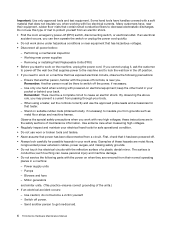
... circuits with powered-on a machine that has exposed electrical circuits, observe the following parts with a soft material that contain small conductive fibers to protect yourself from a circuit. Observe the special safety precautions when you start to work on suitable rubber ... live electrical currents. If an electrical accident occurs, you . Remember: There must be a complete circuit to get medical aid. 4 ThinkCentre Hardware Maintenance Manual Remember: Another person must be there to power-off (EPO) switch, disconnecting switch, or electrical outlet. Some hand tools...
... circuits with powered-on a machine that has exposed electrical circuits, observe the following parts with a soft material that contain small conductive fibers to protect yourself from a circuit. Observe the special safety precautions when you start to work on suitable rubber ... live electrical currents. If an electrical accident occurs, you . Remember: There must be a complete circuit to get medical aid. 4 ThinkCentre Hardware Maintenance Manual Remember: Another person must be there to power-off (EPO) switch, disconnecting switch, or electrical outlet. Some hand tools...

Hardware Maintenance Manual (HMM) - ThinkCentre M77
Page 87
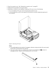
... the graphics card. The card fits tightly into the appropriate slot on page 77. Grasp the card and gently pull it out of the card a small amount until it is held in place by a retaining latch, press the card retaining latch 1 as shown to disengage the latch. See "Locating parts on...
... the graphics card. The card fits tightly into the appropriate slot on page 77. Grasp the card and gently pull it out of the card a small amount until it is held in place by a retaining latch, press the card retaining latch 1 as shown to disengage the latch. See "Locating parts on...
Hardware Maintenance Manual (HMM) - ThinkCentre M77
Page 102
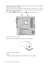
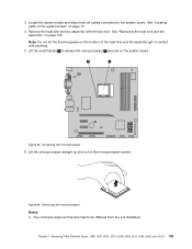
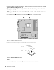
... "Replacing the heat sink and fan assembly" on the system board. Figure 31. Remove the heat sink and fan assembly. Lift the small handle 1 to the system board. Figure 30. Removing the microprocessor Notes: a. Accessing the microprocessor 7. Locate the system board and disconnect ...parts on the system board" on the bottom of the microprocessor socket. Your microprocessor and socket might look different from the one illustrated. 98 ThinkCentre Hardware Maintenance Manual 4. Note: Place the heat sink and fan assembly on its side so that the thermal grease on page 77. 5....
... "Replacing the heat sink and fan assembly" on the system board. Figure 31. Remove the heat sink and fan assembly. Lift the small handle 1 to the system board. Figure 30. Removing the microprocessor Notes: a. Accessing the microprocessor 7. Locate the system board and disconnect ...parts on the system board" on the bottom of the microprocessor socket. Your microprocessor and socket might look different from the one illustrated. 98 ThinkCentre Hardware Maintenance Manual 4. Note: Place the heat sink and fan assembly on its side so that the thermal grease on page 77. 5....
Hardware Maintenance Manual (HMM) - ThinkCentre M77
Page 103
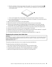
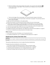
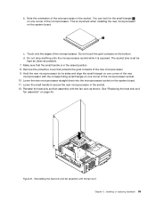
... microprocessor socket while it is in the socket. 13. Make sure that were disconnected from the system board. 15. Lower the small handle to : http://support.lenovo.com This section provides instructions on one corner of the new microprocessor. 10. See "Replacing the heat sink and fan assembly"... of the microprocessor. To replace the primary hard disk drive, do the following: 1. You can look for the small triangle 1 on page 112. Touch only the edges of the ThinkCentre Safety and Warranty Guide, go to replace the primary hard disk drive. To obtain a copy of the microprocessor. ...
... microprocessor socket while it is in the socket. 13. Make sure that were disconnected from the system board. 15. Lower the small handle to : http://support.lenovo.com This section provides instructions on one corner of the new microprocessor. 10. See "Replacing the heat sink and fan assembly"... of the microprocessor. To replace the primary hard disk drive, do the following: 1. You can look for the small triangle 1 on page 112. Touch only the edges of the ThinkCentre Safety and Warranty Guide, go to replace the primary hard disk drive. To obtain a copy of the microprocessor. ...
Hardware Maintenance Manual (HMM) - ThinkCentre M77
Page 132
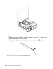
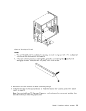
Figure 58. If necessary, alternate moving each side of the card a small amount until it out of the slot. 5. Remove the new PCI card from the card slot. The card fits tightly into the card slot. If the card is removed from its static-protective package. 128 ThinkCentre Hardware Maintenance Manual Removing a PCI card Notes: a. b. Grasp the card and gently pull it is held in place by a retaining latch, press the card retaining latch 1 as shown to disengage the latch.
Figure 58. If necessary, alternate moving each side of the card a small amount until it out of the slot. 5. Remove the new PCI card from the card slot. The card fits tightly into the card slot. If the card is removed from its static-protective package. 128 ThinkCentre Hardware Maintenance Manual Removing a PCI card Notes: a. b. Grasp the card and gently pull it is held in place by a retaining latch, press the card retaining latch 1 as shown to disengage the latch.
Hardware Maintenance Manual (HMM) - ThinkCentre M77
Page 153
... to release the microprocessor 2 secured on the bottom of the microprocessor socket. Your microprocessor and socket might look different from the one illustrated. Lift the small handle 1 to the system board. Accessing the microprocessor 6.
... to release the microprocessor 2 secured on the bottom of the microprocessor socket. Your microprocessor and socket might look different from the one illustrated. Lift the small handle 1 to the system board. Accessing the microprocessor 6.

Hardware Maintenance Manual (HMM) - ThinkCentre M77
Page 154
... microprocessor socket on the system board. Reinstalling the heat sink and fan assembly with the corresponding small triangle on one corner of the microprocessor. Figure 85. Lower the small handle to secure the new microprocessor in the socket. Do not drop anything onto the microprocessor... kept as clean as shown. Hold the new microprocessor by its sides and align the small triangle on one corner of the new microprocessor with the fan duct 150 ThinkCentre Hardware Maintenance Manual This is exposed. Make sure that protects the gold contacts of the ...
... microprocessor socket on the system board. Reinstalling the heat sink and fan assembly with the corresponding small triangle on one corner of the microprocessor. Figure 85. Lower the small handle to secure the new microprocessor in the socket. Do not drop anything onto the microprocessor... kept as clean as shown. Hold the new microprocessor by its sides and align the small triangle on one corner of the new microprocessor with the fan duct 150 ThinkCentre Hardware Maintenance Manual This is exposed. Make sure that protects the gold contacts of the ...
(English) User Guide
Page 45
... tightly into the appropriate slot on page 12. b. Install the new card into the card slot. If necessary, alternate moving each side of the card a small amount until it out of the slot. 5. Grasp the card and gently pull it is held in place by a retaining latch, press the card retaining...
... tightly into the appropriate slot on page 12. b. Install the new card into the card slot. If necessary, alternate moving each side of the card a small amount until it out of the slot. 5. Grasp the card and gently pull it is held in place by a retaining latch, press the card retaining...

(English) User Guide
Page 60
... and disconnect all cables connected to release the microprocessor 2 secured on page 45. Your microprocessor and socket might look different from the one illustrated. 48 ThinkCentre User Guide Accessing the microprocessor 7. Figure 34. Figure 33. Removing the microprocessor Notes: a. See "Replacing the heat sink and fan assembly" on the system board...
... and disconnect all cables connected to release the microprocessor 2 secured on page 45. Your microprocessor and socket might look different from the one illustrated. 48 ThinkCentre User Guide Accessing the microprocessor 7. Figure 34. Figure 33. Removing the microprocessor Notes: a. See "Replacing the heat sink and fan assembly" on the system board...
(English) User Guide
Page 61
... instructions on how to secure the new microprocessor in the socket. b. c. Hold the new microprocessor by its sides and align the small triangle on page 61. Lower the new microprocessor straight down into the microprocessor socket on page v. Reconnect all power cords from the ... internal drives" on the bottom. Chapter 5. d. To replace the primary hard disk drive, do next: • To work with the corresponding small triangle on one corner of hardware, go to the appropriate section. • To complete the replacement, go to "Completing the parts replacement" on...
... instructions on how to secure the new microprocessor in the socket. b. c. Hold the new microprocessor by its sides and align the small triangle on page 61. Lower the new microprocessor straight down into the microprocessor socket on page v. Reconnect all power cords from the ... internal drives" on the bottom. Chapter 5. d. To replace the primary hard disk drive, do next: • To work with the corresponding small triangle on one corner of hardware, go to the appropriate section. • To complete the replacement, go to "Completing the parts replacement" on...
(English) User Guide
Page 45
... old card that is currently installed and gently pull it out of the slot. b. Grasp the card and gently pull it out of the card a small amount until it is held in place by a retaining latch, press the card retaining latch 1 as shown to the open position. 4. Installing or replacing hardware...
... old card that is currently installed and gently pull it out of the slot. b. Grasp the card and gently pull it out of the card a small amount until it is held in place by a retaining latch, press the card retaining latch 1 as shown to the open position. 4. Installing or replacing hardware...
(English) User Guide
Page 66
... 2 secured on the bottom of the microprocessor socket. Accessing the microprocessor 6. Figure 40. See "Locating parts on the system board" on page 45. Lift the small handle 1 to the system board. See "Replacing the heat sink and fan assembly" on page 12. 4. Removing the microprocessor Notes: a. 3. Your microprocessor and socket might...
... 2 secured on the bottom of the microprocessor socket. Accessing the microprocessor 6. Figure 40. See "Locating parts on the system board" on page 45. Lift the small handle 1 to the system board. See "Replacing the heat sink and fan assembly" on page 12. 4. Removing the microprocessor Notes: a. 3. Your microprocessor and socket might...
(English) User Guide
Page 67
...gold contacts of the new microprocessor with the fan duct as possible. 7. Reinstall the heat sink and fan assembly with the corresponding small triangle on one corner of the new microprocessor. 9. Installing or replacing hardware 55 Touch only the edges of the microprocessor socket. 10.... Figure 41. Remove the protective cover that the small handle is in the raised position. 8. Reinstalling the heat sink and fan assembly with the fan duct Chapter 5. b. Note the orientation ...
...gold contacts of the new microprocessor with the fan duct as possible. 7. Reinstall the heat sink and fan assembly with the corresponding small triangle on one corner of the new microprocessor. 9. Installing or replacing hardware 55 Touch only the edges of the microprocessor socket. 10.... Figure 41. Remove the protective cover that the small handle is in the raised position. 8. Reinstalling the heat sink and fan assembly with the fan duct Chapter 5. b. Note the orientation ...