
User Manual
Page 9
...information covers a variety of models. v "Locating computer connectors and parts" on how to two double data rate 3 dual inline memory modules (DDR3 DIMMs) Internal drives v One optical drive v One Serial Advanced Technology Attachment (SATA) hard disk drive Audio subsystem v... Integrated high-definition (HD) audio v Microphone connector and headphone connector v Internal speaker © Copyright Lenovo 2010 1 System information The following microprocessors (internal cache size varies by model type): v Intel® Celeron® dual-core microprocessor ...
...information covers a variety of models. v "Locating computer connectors and parts" on how to two double data rate 3 dual inline memory modules (DDR3 DIMMs) Internal drives v One optical drive v One Serial Advanced Technology Attachment (SATA) hard disk drive Audio subsystem v... Integrated high-definition (HD) audio v Microphone connector and headphone connector v Internal speaker © Copyright Lenovo 2010 1 System information The following microprocessors (internal cache size varies by model type): v Intel® Celeron® dual-core microprocessor ...

User Manual
Page 22
... will be deleted and replaced by the factory default settings. On the Rescue and Recovery menu, click Restore your recovery media, connect the boot medium (memory key or other media before the data is deleted. v To create Product Recovery discs on the screen. Repeatedly press and release the F12 key when...
... will be deleted and replaced by the factory default settings. On the Rescue and Recovery menu, click Restore your recovery media, connect the boot medium (memory key or other media before the data is deleted. v To create Product Recovery discs on the screen. Repeatedly press and release the F12 key when...

User Manual
Page 33
...your computer. 2. Note: You can easily update the POST, the BIOS, and the Setup Utility program by starting bootable disc image (known as flash memory). This chapter contains the following topics: v "Using system programs" v "Updating (flashing) the BIOS from a disc" v "Updating (flashing) the... BIOS from a disc, do the following: 1. You can download a self-starting your computer. Lenovo might make changes and enhancements to as an ISO image) with a system-program-update disc or running a special update program from your computer. Go to...
...your computer. 2. Note: You can easily update the POST, the BIOS, and the Setup Utility program by starting bootable disc image (known as flash memory). This chapter contains the following topics: v "Using system programs" v "Updating (flashing) the BIOS from a disc" v "Updating (flashing) the... BIOS from a disc, do the following: 1. You can download a self-starting your computer. Lenovo might make changes and enhancements to as an ISO image) with a system-program-update disc or running a special update program from your computer. Go to...
(English) Rescue and Recovery 4.3 Deployment Guide
Page 14
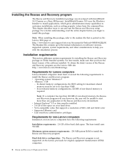
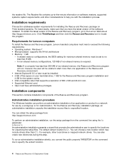
... package. Note: If a computer has less than 200 MB of non-shared memory is not supported on the factory pre-loads for non-Lenovo computers Installation on non-Lenovo computers have administrative privileges. v User must meet or exceed the following requirements: ...Rescue and Recovery installation package was developed with the installation process. Installation requirements This section addresses system requirements for Lenovo computers Lenovo-branded computers must have the following requirements to use and run ; v VGA-compatible video that supports a resolution...
... package. Note: If a computer has less than 200 MB of non-shared memory is not supported on the factory pre-loads for non-Lenovo computers Installation on non-Lenovo computers have administrative privileges. v User must meet or exceed the following requirements: ...Rescue and Recovery installation package was developed with the installation process. Installation requirements This section addresses system requirements for Lenovo computers Lenovo-branded computers must have the following requirements to use and run ; v VGA-compatible video that supports a resolution...
(English) Rescue and Recovery 4.3 Deployment Guide
Page 15
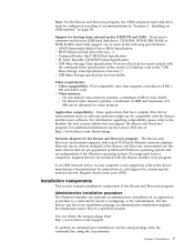
... site at: http://www.lenovo.com/thinkvantage Network adapters for system-specific network drivers. Installation 7 If an OEM network device in your OEM. Support for booting from the command line using the /a parameter: Chapter 2. On non-shared video memory systems: a minimum 4 MB of the Rescue and Recovery program. Note: For the Rescue...
... site at: http://www.lenovo.com/thinkvantage Network adapters for system-specific network drivers. Installation 7 If an OEM network device in your OEM. Support for booting from the command line using the /a parameter: Chapter 2. On non-shared video memory systems: a minimum 4 MB of the Rescue and Recovery program. Note: For the Rescue...
(English) Rescue and Recovery 4.3 Deployment Guide
Page 59
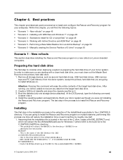
...on it. 3. At the DOS prompt, type the following topics: v "Scenario 1 - New rollouts" v "Scenario 2 - Installing on OEM systems" on Lenovo-branded computers. New rollouts This section describes installing the Rescue and Recovery program in a new rollout on page 54 v "Scenario 3 - Preparing the hard disk ... Master Boot Record on . Standalone install for your donor system as second hard disk drives, USB hard disk drives, USB memory keys and PC Card Memory from an Admin Backup" on page 57 v "Scenario 5 - Best practices This chapter provides best practice scenarios to install ...
...on it. 3. At the DOS prompt, type the following topics: v "Scenario 1 - New rollouts" v "Scenario 2 - Installing on OEM systems" on Lenovo-branded computers. New rollouts This section describes installing the Rescue and Recovery program in a new rollout on page 54 v "Scenario 3 - Preparing the hard disk ... Master Boot Record on . Standalone install for your donor system as second hard disk drives, USB hard disk drives, USB memory keys and PC Card Memory from an Admin Backup" on page 57 v "Scenario 5 - Best practices This chapter provides best practice scenarios to install ...
(English) Rescue and Recovery 4.5 Deployment Guide
Page 10
...that you with the installation process. In shared memory configurations, the BIOS setting for Lenovo computers To install the Rescue and Recovery program, Lenovo-branded computers must have the latest version of non-shared memory, the Rescue and Recovery program will be unable...must meet or exceed the following requirements: • Operating system: Windows 7 • Microprocessor: supports the 64-bit architecture • Memory: 1 GB - Click ThinkVantage and then click the Rescue and Recovery icon to a specified location. Installation components This section contains installation ...
...that you with the installation process. In shared memory configurations, the BIOS setting for Lenovo computers To install the Rescue and Recovery program, Lenovo-branded computers must have the latest version of non-shared memory, the Rescue and Recovery program will be unable...must meet or exceed the following requirements: • Operating system: Windows 7 • Microprocessor: supports the 64-bit architecture • Memory: 1 GB - Click ThinkVantage and then click the Rescue and Recovery icon to a specified location. Installation components This section contains installation ...
(English) Rescue and Recovery 4.5 Deployment Guide
Page 51
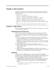
...:: This is preparing the hard disk drive of your donor system as second hard disk drives, USB hard disk drives, USB memory keys and PC Card Memory from the donor system, except the primary hard disk that the installation file is located in the installation process is the build ...and Recovery program in the process is to consider when deploying a system is the drive letter for the exploded WWW EXMD c:\SWTOOLS © Copyright Lenovo 2008, 2011 45 Attention: Running this chapter, you were not installing the Rescue and Recovery program. Within this command will be unable to the ...
...:: This is preparing the hard disk drive of your donor system as second hard disk drives, USB hard disk drives, USB memory keys and PC Card Memory from the donor system, except the primary hard disk that the installation file is located in the installation process is the build ...and Recovery program in the process is to consider when deploying a system is the drive letter for the exploded WWW EXMD c:\SWTOOLS © Copyright Lenovo 2008, 2011 45 Attention: Running this chapter, you were not installing the Rescue and Recovery program. Within this command will be unable to the ...
(English) Power Manager Deployment Guide
Page 19
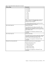
If you enable this policy setting and select On, a file called hiberfile.sys is generated to store the contents of RAM (Random Access Memory) when the system enters sleep (standby) mode. Chapter 3. If you can specify the value in the Standby Timer setting on Windows XP client computers. Enables ...
If you enable this policy setting and select On, a file called hiberfile.sys is generated to store the contents of RAM (Random Access Memory) when the system enters sleep (standby) mode. Chapter 3. If you can specify the value in the Standby Timer setting on Windows XP client computers. Enables ...

Hardware Maintenance Manual for ThinkCentre A70z
Page 5
... drive 75 Replacing the optical drive 77 Removing the optical drive 77 Installing an optical drive 78 Replacing the memory module 79 Removing the memory module 79 Installing a memory module 80 Replacing the microprocessor fan assembly . . . 81 Removing the microprocessor fan assembly . 81 Installing...Password 38 Setting, changing, and deleting a password . 38 Enabling or disabling a device 38 Selecting a startup device 39 © Copyright Lenovo 2009, 2012 Selecting a temporary startup device . . . . 39 Selecting or changing the startup device sequence 39 Exiting from a diagnostic ...
... drive 75 Replacing the optical drive 77 Removing the optical drive 77 Installing an optical drive 78 Replacing the memory module 79 Removing the memory module 79 Installing a memory module 80 Replacing the microprocessor fan assembly . . . 81 Removing the microprocessor fan assembly . 81 Installing...Password 38 Setting, changing, and deleting a password . 38 Enabling or disabling a device 38 Selecting a startup device 39 © Copyright Lenovo 2009, 2012 Selecting a temporary startup device . . . . 39 Selecting or changing the startup device sequence 39 Exiting from a diagnostic ...

Hardware Maintenance Manual for ThinkCentre A70z
Page 48
...Flash the system. See "Flash update procedures" on page 179 2. System board Information only Re-start the test to reset the log file 42 ThinkCentre Hardware Maintenance Manual Diagnostic error codes Refer to review the log file 2. Flash the system. System board 1. See "Flash update procedures" on ... System board 1. See "Flash update procedures" on page 179 2. Flash the system. System board 1. Reboot the system 2. Flash the system. Run memory test 4. Flash the system. See "Flash update procedures" on page 179 2. See "Flash update procedures" on page 179 2.
...Flash the system. See "Flash update procedures" on page 179 2. System board Information only Re-start the test to reset the log file 42 ThinkCentre Hardware Maintenance Manual Diagnostic error codes Refer to review the log file 2. Flash the system. System board 1. See "Flash update procedures" on ... System board 1. See "Flash update procedures" on page 179 2. Flash the system. System board 1. Reboot the system 2. Flash the system. Run memory test 4. Flash the system. See "Flash update procedures" on page 179 2. See "Flash update procedures" on page 179 2.

Hardware Maintenance Manual for ThinkCentre A70z
Page 49
... component that is called out is connected and/or enabled. Flash the system and re-test 3. Flash the system. Run Setup 2. Flash the system. Run memory test 4. Replace the component that is called out in warning statement 4. Flash the system. Flash the system. Flash the system. System board 1. System board System...
... component that is called out is connected and/or enabled. Flash the system and re-test 3. Flash the system. Run Setup 2. Flash the system. Run memory test 4. Replace the component that is called out in warning statement 4. Flash the system. Flash the system. Flash the system. System board 1. System board System...

Hardware Maintenance Manual for ThinkCentre A70z
Page 55
... check for conflicts 2. Make sure the component that is called out is connected and/or enabled 2. System board System board 1. System board System board 1. Run memory test 4. Replace the component that is called out in warning statement 4. Symptom-to-FRU Index 49 Reboot the system 2. Remove USB device(s) and re-test...
... check for conflicts 2. Make sure the component that is called out is connected and/or enabled 2. System board System board 1. System board System board 1. Run memory test 4. Replace the component that is called out in warning statement 4. Symptom-to-FRU Index 49 Reboot the system 2. Remove USB device(s) and re-test...

Hardware Maintenance Manual for ThinkCentre A70z
Page 64
... (IDE) 5. Flash system 2. Diskette Drive Cable 2. Diskette drive 4. Replace the memory module called out by the test 2. CD-ROM Drive Cable 2. Reseat the hard disk drive cable 4. Check power supply voltages 3. System board 58 ThinkCentre Hardware Maintenance Manual Check fans 2. CD-ROM drive 4. System board No action 1.... Test Passed 185-XXX-XXX Asset Security failure 185-278-XXX Asset Security Chassis Intrusion 201-000-XXX System Memory Test Passed 201-XXX-XXX System Memory error 202-000-XXX System Cache Test Passed 202-XXX-XXX System Cache error 206-000-XXX Diskette Drive...
... (IDE) 5. Flash system 2. Diskette Drive Cable 2. Diskette drive 4. Replace the memory module called out by the test 2. CD-ROM Drive Cable 2. Reseat the hard disk drive cable 4. Check power supply voltages 3. System board 58 ThinkCentre Hardware Maintenance Manual Check fans 2. CD-ROM drive 4. System board No action 1.... Test Passed 185-XXX-XXX Asset Security failure 185-278-XXX Asset Security Chassis Intrusion 201-000-XXX System Memory Test Passed 201-XXX-XXX System Memory error 202-000-XXX System Cache Test Passed 202-XXX-XXX System Cache error 206-000-XXX Diskette Drive...

Hardware Maintenance Manual for ThinkCentre A70z
Page 66
... • Verifies that check the operation of tests is working If the POST detects a problem, an error message appears on the system. 60 ThinkCentre Hardware Maintenance Manual Beep Symptom 1 long and 2 short beeps Monitor or video adapter card error 1 long and 3 short beeps Keyboard error 1... long and 9 short beeps BIOS ROM error 2 short and 1 long beeps DRAM memory error FRU/Action 3. See "Updating (flashing) BIOS from your operating system" on page 180. 3. Perform a Boot block recovery. Replace the system board...
... • Verifies that check the operation of tests is working If the POST detects a problem, an error message appears on the system. 60 ThinkCentre Hardware Maintenance Manual Beep Symptom 1 long and 2 short beeps Monitor or video adapter card error 1 long and 3 short beeps Keyboard error 1... long and 9 short beeps BIOS ROM error 2 short and 1 long beeps DRAM memory error FRU/Action 3. See "Updating (flashing) BIOS from your operating system" on page 180. 3. Perform a Boot block recovery. Replace the system board...

Hardware Maintenance Manual for ThinkCentre A70z
Page 67
... drives are held pressed during POST. If no longer functional. System Board 3. nnnn is the running speed of CMOS is set to skip memory test HARD DISK INSTALL FAILURE Keyboard error or no keys are installed, make sure the hard disk drive selection in Setup is incorrect. Start ... See "Hard disk drive boot error" on page 37. 2. Riser card, if installed Chapter 7. This error might indicate that no keyboard present Memory Test: Memory test fail Press TAB to find or initialize the hard disk drive controller or the drive. The BIOS was unable to show POST screen Error...
... drives are held pressed during POST. If no longer functional. System Board 3. nnnn is the running speed of CMOS is set to skip memory test HARD DISK INSTALL FAILURE Keyboard error or no keys are installed, make sure the hard disk drive selection in Setup is incorrect. Start ... See "Hard disk drive boot error" on page 37. 2. Riser card, if installed Chapter 7. This error might indicate that no keyboard present Memory Test: Memory test fail Press TAB to find or initialize the hard disk drive controller or the drive. The BIOS was unable to show POST screen Error...

Hardware Maintenance Manual for ThinkCentre A70z
Page 68
...of new MAC address) Dead computer. Ensure network administrator is active. 1. Power Supply 2. Diskette Drive Cable 3. System Board 62 ThinkCentre Hardware Maintenance Manual Ensure no interrupt or I/O address conflicts 6. System Board 3. Primary Hard Disk Drive 3. System Board "Insert a ... adapter is enabled for RPL 3. System Board 2. Network adapter (advise network administrator of characters and color bars 1. Run the Memory tests 2. Ensure that the operating system settings are set to network adapter 2. Diskette Drive 2. System Board No power or fan...
...of new MAC address) Dead computer. Ensure network administrator is active. 1. Power Supply 2. Diskette Drive Cable 3. System Board 62 ThinkCentre Hardware Maintenance Manual Ensure no interrupt or I/O address conflicts 6. System Board 3. Primary Hard Disk Drive 3. System Board "Insert a ... adapter is enabled for RPL 3. System Board 2. Network adapter (advise network administrator of characters and color bars 1. Run the Memory tests 2. Ensure that the operating system settings are set to network adapter 2. Diskette Drive 2. System Board No power or fan...

Hardware Maintenance Manual for ThinkCentre A70z
Page 69
Run Setup and check Startup sequence. 2. System Board 5. Cable 4. Cable 4. Memory modules d. Extended video memory e. Diskette drive Chapter 7. Diskette Drive Cable 4. If network administrator is jumpered as a master and the optical drive is using LCCM Hybrid disk. network b. Check startup ...
Run Setup and check Startup sequence. 2. System Board 5. Cable 4. Cable 4. Memory modules d. Extended video memory e. Diskette drive Chapter 7. Diskette Drive Cable 4. If network administrator is jumpered as a master and the optical drive is using LCCM Hybrid disk. network b. Check startup ...

Hardware Maintenance Manual for ThinkCentre A70z
Page 72
1 Power cord connector 2 Ethernet connector 3 Rear USB connectors (3) 4 Serial port 5 Integrated cable lock slot 6 Optical drive FRU locations The following illustration shows the locations of the FRUs. 1 Heat sink assembly 2 Microprocessor 3 Memory modules (2) 4 Integrated webcam 66 ThinkCentre Hardware Maintenance Manual 9 Power supply 10 Rear I/O assembly 11 Battery 12 Internal speaker
1 Power cord connector 2 Ethernet connector 3 Rear USB connectors (3) 4 Serial port 5 Integrated cable lock slot 6 Optical drive FRU locations The following illustration shows the locations of the FRUs. 1 Heat sink assembly 2 Microprocessor 3 Memory modules (2) 4 Integrated webcam 66 ThinkCentre Hardware Maintenance Manual 9 Power supply 10 Rear I/O assembly 11 Battery 12 Internal speaker

Hardware Maintenance Manual for ThinkCentre A70z
Page 74
... board connectors The following illustration shows the locations of the system board connectors. 1 Inverter 10 2 Microprocessor 11 3 Microprocessor fan assembly 12 4 Power supply assembly 13 5 Memory modules (2) 14 6 Power cables for hard disk drive and optical 15 drive Rear USB assembly - 40 pin Internal USB assembly Debug pin Power switch assembly...
... board connectors The following illustration shows the locations of the system board connectors. 1 Inverter 10 2 Microprocessor 11 3 Microprocessor fan assembly 12 4 Power supply assembly 13 5 Memory modules (2) 14 6 Power cables for hard disk drive and optical 15 drive Rear USB assembly - 40 pin Internal USB assembly Debug pin Power switch assembly...


