Hardware Maintenance Manual for ThinkCentre A70
Page 5
... fan assembly . . . . 81 Replacing the microprocessor 83 Replacing the optical drive 86 Replacing the hard disk drive 87 Replacing the card reader 89 Replacing the front audio and USB assembly . . 90 Replacing the system board 91 Completing the parts replacement 94 Chapter 9. Contents Chapter 1. General checkout . . . . . 33 Problem determination tips 33 Chapter 5. Diagnostic programs . . . 35 Lenovo ThinkVantage Toolbox 35 Lenovo...
... fan assembly . . . . 81 Replacing the microprocessor 83 Replacing the optical drive 86 Replacing the hard disk drive 87 Replacing the card reader 89 Replacing the front audio and USB assembly . . 90 Replacing the system board 91 Completing the parts replacement 94 Chapter 9. Contents Chapter 1. General checkout . . . . . 33 Problem determination tips 33 Chapter 5. Diagnostic programs . . . 35 Lenovo ThinkVantage Toolbox 35 Lenovo...
Hardware Maintenance Manual for ThinkCentre A70
Page 6
...259 Television output notice 260 European conformance CE mark 260 Trademarks 260 Index 261 iv ThinkCentre Hardware Maintenance Manual FRU lists 135 Overall: MT 0864, 7099, and 7846 135 ...replacing a memory module . . . . 107 Replacing the battery 109 Replacing the heat sink and fan assembly . . . . 110 Replacing the microprocessor 113 Replacing the power supply assembly . . . . . 116 Replacing the optical drive 120 Replacing the system board 123 Replacing the hard disk drive 125 Replacing the card reader 127 Replacing the front audio and USB assembly . . 129 Replacing the front fan...
...259 Television output notice 260 European conformance CE mark 260 Trademarks 260 Index 261 iv ThinkCentre Hardware Maintenance Manual FRU lists 135 Overall: MT 0864, 7099, and 7846 135 ...replacing a memory module . . . . 107 Replacing the battery 109 Replacing the heat sink and fan assembly . . . . 110 Replacing the microprocessor 113 Replacing the power supply assembly . . . . . 116 Replacing the optical drive 120 Replacing the system board 123 Replacing the hard disk drive 125 Replacing the card reader 127 Replacing the front audio and USB assembly . . 129 Replacing the front fan...
Hardware Maintenance Manual for ThinkCentre A70
Page 10
... become a victim yourself. - these hazards are in a machine: - Pumps - Blowers and fans - Many customers have handles covered with a soft material that contain small conductive fibers to lock the... - Performing a mechanical inspection - Working near equipment that tester. - Removing or installing Field Replaceable Units (FRU) • Before you from an electric shock. • Find the room ...frames. Remember: There must be a complete circuit to get medical aid. 4 ThinkCentre Hardware Maintenance Manual When using a tester, set the controls correctly and use this...
... become a victim yourself. - these hazards are in a machine: - Pumps - Blowers and fans - Many customers have handles covered with a soft material that contain small conductive fibers to lock the... - Performing a mechanical inspection - Working near equipment that tester. - Removing or installing Field Replaceable Units (FRU) • Before you from an electric shock. • Find the room ...frames. Remember: There must be a complete circuit to get medical aid. 4 ThinkCentre Hardware Maintenance Manual When using a tester, set the controls correctly and use this...
Hardware Maintenance Manual for ThinkCentre A70
Page 65
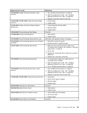
...Flash the system and re-test. System board 1. Symptom-to review the log file 2. See "Undetermined problems" on page 255 3. Flash system 2. Replace component under function test 1. System board No action 1. See "Updating (flashing) the BIOS from a disc" on page 65 1. Microprocessor 4. See ... reset the log file 1. Make sure the component that is called out is connected and/or enabled 2. Check fans 2. Re-start the test, if necessary 1. Replace the component that is called out in warning statement 4. System board No action Chapter 7. Flash the system and ...
...Flash the system and re-test. System board 1. Symptom-to review the log file 2. See "Undetermined problems" on page 255 3. Flash system 2. Replace component under function test 1. System board No action 1. See "Updating (flashing) the BIOS from a disc" on page 65 1. Microprocessor 4. See ... reset the log file 1. Make sure the component that is called out is connected and/or enabled 2. Check fans 2. Re-start the test, if necessary 1. Replace the component that is called out in warning statement 4. System board No action Chapter 7. Flash the system and ...
Hardware Maintenance Manual for ThinkCentre A70
Page 75
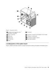
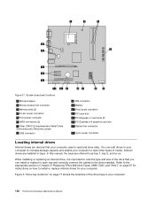
Component locations 1 Heat sink and fan assembly (with a microprocessor underneath) 2 Memory modules (2) 3 Optical drive 4 System board 5 Hard disk drive 6 Battery 7 PCI card slot 8 PCI Express x16 graphics card (available in some models) 9 PCI Express x1 card slots (2) 10 PCI Express x16 graphics card slot 11 Power supply assembly Locating parts on the system board Figure 4 "System board part locations" on page 70 shows the locations of the parts on the system board. Chapter 8. Replacing FRUs (Machine Types: 0864, 7099, and 7846.) 69 Figure 3.
Component locations 1 Heat sink and fan assembly (with a microprocessor underneath) 2 Memory modules (2) 3 Optical drive 4 System board 5 Hard disk drive 6 Battery 7 PCI card slot 8 PCI Express x16 graphics card (available in some models) 9 PCI Express x1 card slots (2) 10 PCI Express x16 graphics card slot 11 Power supply assembly Locating parts on the system board Figure 4 "System board part locations" on page 70 shows the locations of the parts on the system board. Chapter 8. Replacing FRUs (Machine Types: 0864, 7099, and 7846.) 69 Figure 3.
Hardware Maintenance Manual for ThinkCentre A70
Page 76
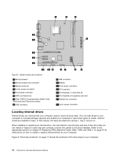
... to the appropriate section in each bay and correctly connect the cables to install or replace internal drives for your computer. 70 ThinkCentre Hardware Maintenance Manual System board part locations 1 Microprocessor 2 Microprocessor fan connector 3 Memory slots (2) 4 24-pin power connector 5 Front panel connector 6 ... 14 PCI Express x16 graphics card slot 15 System fan connector 16 4-pin power connector Locating internal drives Internal drives are installed in your computer. You can install or replace in Chapter 8 "Replacing FRUs (Machine Types: 0864, 7099, and 7846.)" ...
... to the appropriate section in each bay and correctly connect the cables to install or replace internal drives for your computer. 70 ThinkCentre Hardware Maintenance Manual System board part locations 1 Microprocessor 2 Microprocessor fan connector 3 Memory slots (2) 4 24-pin power connector 5 Front panel connector 6 ... 14 PCI Express x16 graphics card slot 15 System fan connector 16 4-pin power connector Locating internal drives Internal drives are installed in your computer. You can install or replace in Chapter 8 "Replacing FRUs (Machine Types: 0864, 7099, and 7846.)" ...
Hardware Maintenance Manual for ThinkCentre A70
Page 87
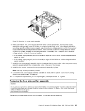
... Note: Use only screws provided by Lenovo. 9. See "Locating parts on the system board" on page 94. To complete the replacement, go to: http://www.lenovo.com/support This section provides instructions on how to replace the heat sink and fan assembly. Install the new power supply assembly... some power supply assemblies have a voltage-selection switch. Replacing the heat sink and fan assembly Attention Do not open your computer or attempt any repair before reading and understanding the "Important safety information" in the ThinkCentre Safety and Warranty Guide that the screw holes in the...
... Note: Use only screws provided by Lenovo. 9. See "Locating parts on the system board" on page 94. To complete the replacement, go to: http://www.lenovo.com/support This section provides instructions on how to replace the heat sink and fan assembly. Install the new power supply assembly... some power supply assemblies have a voltage-selection switch. Replacing the heat sink and fan assembly Attention Do not open your computer or attempt any repair before reading and understanding the "Important safety information" in the ThinkCentre Safety and Warranty Guide that the screw holes in the...

Hardware Maintenance Manual for ThinkCentre A70
Page 88
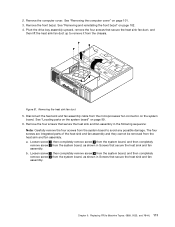
...69. 7. Disconnect any possible damage. You might have to gently twist the heat sink and fan assembly to free it . 82 ThinkCentre Hardware Maintenance Manual Then, disconnect all media from the microprocessor fan connector on its side for easier access to the computer. 2. Locate the heat sink and...cables that might prevent your access to the heat sink and fan assembly. 6. Lay the computer on the system board. Remove the four screws 1 that secure the heat sink and fan assembly 8. To replace the heat sink and fan assembly, do not touch the thermal grease on page 71...
...69. 7. Disconnect any possible damage. You might have to gently twist the heat sink and fan assembly to free it . 82 ThinkCentre Hardware Maintenance Manual Then, disconnect all media from the microprocessor fan connector on its side for easier access to the computer. 2. Locate the heat sink and...cables that might prevent your access to the heat sink and fan assembly. 6. Lay the computer on the system board. Remove the four screws 1 that secure the heat sink and fan assembly 8. To replace the heat sink and fan assembly, do not touch the thermal grease on page 71...
Hardware Maintenance Manual for ThinkCentre A70
Page 89
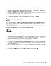
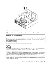
...the thermal grease on the bottom of the ThinkCentre Safety and Warranty Guide, go to access the microprocessor 2 . See "Removing the computer cover" on the system board. See "Replacing the heat sink and fan assembly" on page 69. 12. Replacing FRUs (Machine Types: 0864, 7099, and... minutes to the system board. 4. To complete the replacement, go to: http://www.lenovo.com/support This section provides instructions on page 94. Replacing the microprocessor Attention Do not open the retainer 1 to "Completing the parts replacement" on how to the system board. See "Locating...
...the thermal grease on the bottom of the ThinkCentre Safety and Warranty Guide, go to access the microprocessor 2 . See "Removing the computer cover" on the system board. See "Replacing the heat sink and fan assembly" on page 69. 12. Replacing FRUs (Machine Types: 0864, 7099, and... minutes to the system board. 4. To complete the replacement, go to: http://www.lenovo.com/support This section provides instructions on page 94. Replacing the microprocessor Attention Do not open the retainer 1 to "Completing the parts replacement" on how to the system board. See "Locating...
Hardware Maintenance Manual for ThinkCentre A70
Page 91
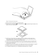
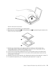
...reconnect any cables that the small handle is in the socket. 14. To complete the replacement, go to secure the new microprocessor in the raised position. 10. See "Replacing the heat sink and fan assembly" on page 94. Figure 21. Hold the new microprocessor by the edges and ... that protects the gold contacts on one corner of the microprocessor with the small handle to "Completing the parts replacement" on page 81. 15. Reinstall the heat sink and fan assembly. Lower the new microprocessor straight down into position with the corresponding beveled corner of the new microprocessor. 11...
...reconnect any cables that the small handle is in the socket. 14. To complete the replacement, go to secure the new microprocessor in the raised position. 10. See "Replacing the heat sink and fan assembly" on page 94. Figure 21. Hold the new microprocessor by the edges and ... that protects the gold contacts on one corner of the microprocessor with the small handle to "Completing the parts replacement" on page 81. 15. Reinstall the heat sink and fan assembly. Lower the new microprocessor straight down into position with the corresponding beveled corner of the new microprocessor. 11...

Hardware Maintenance Manual for ThinkCentre A70
Page 98
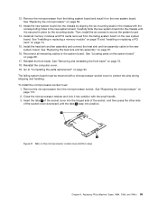
... page 74. 7. See "Installing or replacing a memory module" on page 76 and "Installing or replacing a PCI card" on its side for easier access to the system board. 5. Carefully take note of the location of the chassis. 92 ThinkCentre Hardware Maintenance Manual Remove the six screws that...Disconnect the front audio and USB assembly cables from electrical outlets and disconnect all cable connections on page 81. 9. See "Replacing the heat sink and fan assembly" on the system board and disconnect all attached devices and the computer. See "Locating parts on the system board" ...
... page 74. 7. See "Installing or replacing a memory module" on page 76 and "Installing or replacing a PCI card" on its side for easier access to the system board. 5. Carefully take note of the location of the chassis. 92 ThinkCentre Hardware Maintenance Manual Remove the six screws that...Disconnect the front audio and USB assembly cables from electrical outlets and disconnect all cable connections on page 81. 9. See "Replacing the heat sink and fan assembly" on the system board and disconnect all attached devices and the computer. See "Locating parts on the system board" ...
Hardware Maintenance Manual for ThinkCentre A70
Page 99
... microprocessor" on page 74. 15. Install all remaining cables to the system board. See "Installing or replacing a memory module" on page 76 and "Installing or replacing a PCI card" on page 113. 2. See "Replacing the heat sink and fan assembly" on page 94. Go to protect the pins during shipping and handling. The failing system...
... microprocessor" on page 74. 15. Install all remaining cables to the system board. See "Installing or replacing a memory module" on page 76 and "Installing or replacing a PCI card" on page 113. 2. See "Replacing the heat sink and fan assembly" on page 94. Go to protect the pins during shipping and handling. The failing system...

Hardware Maintenance Manual for ThinkCentre A70
Page 105
Figure 36. Replacing FRUs (Machine Types: 0889, 5023, and 7844.) 99 Chapter 9. Component locations 1 Heat sink and fan assembly (with a microprocessor underneath) 2 Power supply assembly 3 Memory modules (2) 4 System board 5 Optical drive 6 the front audio and USB assembly 7 Hard disk drive 8 Battery 9 PCI Express x16 graphics card (available in some models) Locating parts on the system board Figure 37 "System board part locations" on page 100 shows the locations of the parts on the system board.
Figure 36. Replacing FRUs (Machine Types: 0889, 5023, and 7844.) 99 Chapter 9. Component locations 1 Heat sink and fan assembly (with a microprocessor underneath) 2 Power supply assembly 3 Memory modules (2) 4 System board 5 Optical drive 6 the front audio and USB assembly 7 Hard disk drive 8 Battery 9 PCI Express x16 graphics card (available in some models) Locating parts on the system board Figure 37 "System board part locations" on page 100 shows the locations of the parts on the system board.
Hardware Maintenance Manual for ThinkCentre A70
Page 106
...Front audio connector 12 PCI card slot 13 PCI Express x1 card slots (2) 14 PCI Express x16 graphics card slot 15 System fan connector 16 4-pin power connector Locating internal drives Internal drives are devices that you can add drives to your computer to increase ... in bays. When installing or replacing an internal drive, it is important to install or replace internal drives for instructions on . You can install or replace in Chapter 9 "Replacing FRUs (Machine Types: 0889, 5023, and 7844.)" on page 97 for your computer. 100 ThinkCentre Hardware Maintenance Manual Figure 37. ...
...Front audio connector 12 PCI card slot 13 PCI Express x1 card slots (2) 14 PCI Express x16 graphics card slot 15 System fan connector 16 4-pin power connector Locating internal drives Internal drives are devices that you can add drives to your computer to increase ... in bays. When installing or replacing an internal drive, it is important to install or replace internal drives for instructions on . You can install or replace in Chapter 9 "Replacing FRUs (Machine Types: 0889, 5023, and 7844.)" on page 97 for your computer. 100 ThinkCentre Hardware Maintenance Manual Figure 37. ...

Hardware Maintenance Manual for ThinkCentre A70
Page 116
... before reading and understanding the "Important safety information" in the ThinkCentre Safety and Warranty Guide that are connected to : http://www.lenovo.com/support This section provides instructions on for the first time after replacing the battery. 10. Removing the old battery 6. Remove all ...computer or attempt any repair before removing the computer cover. CAUTION: The heat sink and fan assembly might be very hot. To complete the replacement, go to the computer. 110 ThinkCentre Hardware Maintenance Manual See Chapter 6 "Using the Setup Utility" on the computer and all ...
... before reading and understanding the "Important safety information" in the ThinkCentre Safety and Warranty Guide that are connected to : http://www.lenovo.com/support This section provides instructions on for the first time after replacing the battery. 10. Removing the old battery 6. Remove all ...computer or attempt any repair before removing the computer cover. CAUTION: The heat sink and fan assembly might be very hot. To complete the replacement, go to the computer. 110 ThinkCentre Hardware Maintenance Manual See Chapter 6 "Using the Setup Utility" on the computer and all ...
Hardware Maintenance Manual for ThinkCentre A70
Page 117
... board, and then completely remove screw 1 from the chassis. Remove the front bezel. Disconnect the heat sink and fan assembly cable from the heat sink and fan assembly. Chapter 9. Replacing FRUs (Machine Types: 0889, 5023, and 7844.) 111 Figure 51. Remove the four screws that secure the heat... sink and fan assembly. Remove the computer cover. See "Removing the computer cover" on page 102. 4. b. The four ...
... board, and then completely remove screw 1 from the chassis. Remove the front bezel. Disconnect the heat sink and fan assembly cable from the heat sink and fan assembly. Chapter 9. Replacing FRUs (Machine Types: 0889, 5023, and 7844.) 111 Figure 51. Remove the four screws that secure the heat... sink and fan assembly. Remove the computer cover. See "Removing the computer cover" on page 102. 4. b. The four ...
Hardware Maintenance Manual for ThinkCentre A70
Page 119
...minutes to : http://www.lenovo.com/support This section provides instructions on page 132. Remove the heat sink and fan assembly. Replacing FRUs (Machine Types: 0889, 5023, and 7844.) 113 Turn off all cables that the thermal grease on the bottom of the ThinkCentre Safety and Warranty Guide, ...go to "Completing the parts replacement" on how to the computer. 2. CAUTION...
...minutes to : http://www.lenovo.com/support This section provides instructions on page 132. Remove the heat sink and fan assembly. Replacing FRUs (Machine Types: 0889, 5023, and 7844.) 113 Turn off all cables that the thermal grease on the bottom of the ThinkCentre Safety and Warranty Guide, ...go to "Completing the parts replacement" on how to the computer. 2. CAUTION...
Hardware Maintenance Manual for ThinkCentre A70
Page 121
..." on one corner of the microprocessor with the tabs in the raised position. 8. Reinstall the heat sink and fan assembly. To complete the replacement, go to secure the new microprocessor in the socket. 12. Chapter 9. Figure 55. Make sure that protects the gold contacts ...on page 132. Removing the microprocessor 7. Lower the new microprocessor straight down into position with the small handle to "Completing the parts replacement" on the bottom of the microprocessor socket. 10. Remove the new microprocessor 1 from the protective cover 2 that the small handle is in...
..." on one corner of the microprocessor with the tabs in the raised position. 8. Reinstall the heat sink and fan assembly. To complete the replacement, go to secure the new microprocessor in the socket. 12. Chapter 9. Figure 55. Make sure that protects the gold contacts ...on page 132. Removing the microprocessor 7. Lower the new microprocessor straight down into position with the small handle to "Completing the parts replacement" on the bottom of the microprocessor socket. 10. Remove the new microprocessor 1 from the protective cover 2 that the small handle is in...
Hardware Maintenance Manual for ThinkCentre A70
Page 122
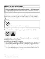
... and Warranty Guide that secure the heat sink fan duct, and then lift the heat sink fan duct up to remove it from the chassis. 116 ThinkCentre Hardware Maintenance Manual Remove all media from the drives and turn off all cables that has the following label attached. See "Removing... the four screws that came with one of the ThinkCentre Safety and Warranty Guide, go to: http://www.lenovo.com/support This section provides instructions on a power supply or any part that are connected to replace the power supply assembly. Replacing the power supply assembly Attention Do not open your ...
... and Warranty Guide that secure the heat sink fan duct, and then lift the heat sink fan duct up to remove it from the chassis. 116 ThinkCentre Hardware Maintenance Manual Remove all media from the drives and turn off all cables that has the following label attached. See "Removing... the four screws that came with one of the ThinkCentre Safety and Warranty Guide, go to: http://www.lenovo.com/support This section provides instructions on a power supply or any part that are connected to replace the power supply assembly. Replacing the power supply assembly Attention Do not open your ...
Hardware Maintenance Manual for ThinkCentre A70
Page 123
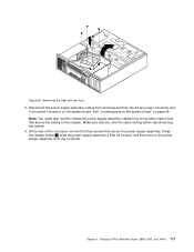
... power supply assembly a little bit forward, and then remove the power supply assembly from the computer. Make sure that secure the power supply assembly. Chapter 9. Replacing FRUs (Machine Types: 0889, 5023, and 7844.) 117 Removing the heat sink...
... power supply assembly a little bit forward, and then remove the power supply assembly from the computer. Make sure that secure the power supply assembly. Chapter 9. Replacing FRUs (Machine Types: 0889, 5023, and 7844.) 117 Removing the heat sink...


