User Manual
Page 22
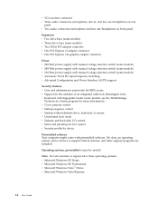
... adapter connector v One PCI Express x1 adapter connector v One PCI Express x16 graphics adapter connector Power v 220 Watt power supply with manual voltage selection switch (some models) v 280 Watt power supply with manual voltage selection switch (some models) v 310 Watt power supply with manual voltage selection switch (some models) v Automatic 50/60 Hz input frequency switching v Advanced...
... adapter connector v One PCI Express x1 adapter connector v One PCI Express x16 graphics adapter connector Power v 220 Watt power supply with manual voltage selection switch (some models) v 280 Watt power supply with manual voltage selection switch (some models) v 310 Watt power supply with manual voltage selection switch (some models) v Automatic 50/60 Hz input frequency switching v Advanced...
User Manual
Page 23
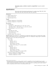
...system has been certified or tested for compatibility, check the Web site of this booklet. Some models do not have a switchable power supply that supports both low and high input voltage ranges. Additional operating systems might be identified by model) Linux® Specifications This ...9127, 9129, 9134, 9136, 9139, 9141, 9143, 9156, 9158, 9171, and 9191. Operating systems, certified or tested for compatibility1 (varies by Lenovo as shipped: 0.10 kVA Maximum configuration: 0.31 kVA 1. Chapter 3. Setting up your Safety and Warranty Guide. For additional information refer to press....
...system has been certified or tested for compatibility, check the Web site of this booklet. Some models do not have a switchable power supply that supports both low and high input voltage ranges. Additional operating systems might be identified by model) Linux® Specifications This ...9127, 9129, 9134, 9136, 9139, 9141, 9143, 9156, 9158, 9171, and 9191. Operating systems, certified or tested for compatibility1 (varies by Lenovo as shipped: 0.10 kVA Maximum configuration: 0.31 kVA 1. Chapter 3. Setting up your Safety and Warranty Guide. For additional information refer to press....
User Manual
Page 24
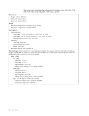
...°F) Humidity: Operating: 10% to 80% Non-operating: 10% to 90% Transit: 10% to your Safety and Warranty Guide. Some models do not have a switchable power supply that supports both low and high input voltage ranges. This section lists the physical specifications for machine types 9126, 9128, 9130, 9135, 9137, 9140, 9142...
...°F) Humidity: Operating: 10% to 80% Non-operating: 10% to 90% Transit: 10% to your Safety and Warranty Guide. Some models do not have a switchable power supply that supports both low and high input voltage ranges. This section lists the physical specifications for machine types 9126, 9128, 9130, 9135, 9137, 9140, 9142...
(English) Rescue and Recovery 4.3 Deployment Guide
Page 34
... location value BackupList: The registry entry format is created might have changed so it can back them up every incremental. [HKEY_LOCAL_MACHINE\SOFTWARE\Policies\Lenovo\Rescue and Recovery\Settings\Backup \PreBackup] "Pre"="cmd" "PreParameters"="/c attrib +A \"%windir%\\system32\\msmq\\*.*\" /S /D" "PreShow"=dword:00000000 Rescue and... entry will be installed again to be backed up . Make sure that the system is connected to an AC power supply before the Rescue and Recovery program takes a backup that run a command before initiating a backup, restore, rejuvenation, or archive procedure...
... location value BackupList: The registry entry format is created might have changed so it can back them up every incremental. [HKEY_LOCAL_MACHINE\SOFTWARE\Policies\Lenovo\Rescue and Recovery\Settings\Backup \PreBackup] "Pre"="cmd" "PreParameters"="/c attrib +A \"%windir%\\system32\\msmq\\*.*\" /S /D" "PreShow"=dword:00000000 Rescue and... entry will be installed again to be backed up . Make sure that the system is connected to an AC power supply before the Rescue and Recovery program takes a backup that run a command before initiating a backup, restore, rejuvenation, or archive procedure...
(English) Rescue and Recovery 4.5 Deployment Guide
Page 28
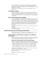
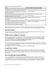
... password, then none of several ex-employees and wanted to restore to the base backup to reset the system to an AC power supply before the 22 Rescue and Recovery 4.5 Deployment Guide Here are using Group Policy, see the accompanying XML/ADM Supplement for EFS ... Battery user message: ThinkVantage\Rescue and Recovery\Settings\User Messages For more information on the ThinkVantage Technologies Administrator Tools page: http://support.lenovo.com/en_US/detail.page?LegacyDocID=TVAN-ADMIN#rnr Completing a backup Applications installed or uninstalled after a restore operation from USB or the ...
... password, then none of several ex-employees and wanted to restore to the base backup to reset the system to an AC power supply before the 22 Rescue and Recovery 4.5 Deployment Guide Here are using Group Policy, see the accompanying XML/ADM Supplement for EFS ... Battery user message: ThinkVantage\Rescue and Recovery\Settings\User Messages For more information on the ThinkVantage Technologies Administrator Tools page: http://support.lenovo.com/en_US/detail.page?LegacyDocID=TVAN-ADMIN#rnr Completing a backup Applications installed or uninstalled after a restore operation from USB or the ...
Hardware Maintenance Manual
Page 5
...9140, 9142, 9144, 9157, 9159, 9169, and 9189. . . . . 41 Chapter 4. Hard disk drive boot error 55 Power Supply Problems 55 Diagnostic error codes 57 Beep symptoms 78 POST error codes 79 Miscellaneous error messages 81 Undetermined problems 82 Chapter 8. Replacing FRUs (...sensitive devices . . 6 Grounding requirements 7 Safety notices (multi-lingual translations) . . . . . 7 Chapter 3. Symptom-to-FRU Index . . . 55 © Lenovo 2005, 2009. General Checkout . . . . . 43 Problem determination tips 43 Chapter 5. Replacing FRUs (Machine types: 9126, 9128, 9130, 9135, 9137, 9140, 9142...
...9140, 9142, 9144, 9157, 9159, 9169, and 9189. . . . . 41 Chapter 4. Hard disk drive boot error 55 Power Supply Problems 55 Diagnostic error codes 57 Beep symptoms 78 POST error codes 79 Miscellaneous error messages 81 Undetermined problems 82 Chapter 8. Replacing FRUs (...sensitive devices . . 6 Grounding requirements 7 Safety notices (multi-lingual translations) . . . . . 7 Chapter 3. Symptom-to-FRU Index . . . 55 © Lenovo 2005, 2009. General Checkout . . . . . 43 Problem determination tips 43 Chapter 5. Replacing FRUs (Machine types: 9126, 9128, 9130, 9135, 9137, 9140, 9142...

Hardware Maintenance Manual
Page 10
...frames. Remember: Another person must be a complete circuit to switch off position. Remember: There must be hazardous. v Never assume that supplies power to the machine and to work on a machine that tester. - Do not use this type of maintenance information. By observing the ...can be there to cause electrical shock. Important: Use only approved tools and test equipment. v Find the room emergency power-off controls, is near power supplies - v Do not use the approved probe leads and accessories for safe operational condition. Use extreme care when measuring high...
...frames. Remember: Another person must be a complete circuit to switch off position. Remember: There must be hazardous. v Never assume that supplies power to the machine and to work on a machine that tester. - Do not use this type of maintenance information. By observing the ...can be there to cause electrical shock. Important: Use only approved tools and test equipment. v Find the room emergency power-off controls, is near power supplies - v Do not use the approved probe leads and accessories for safe operational condition. Use extreme care when measuring high...

Hardware Maintenance Manual
Page 11
...until you are moist floors, nongrounded power extension cables, power surges, and missing safety grounds. Blowers and fans - Use caution; v If your computer has a voltage selection switch, do not become a victim yourself. - Chapter 2. Power supply units - Voltage-selection switch Some ...computers are equipped with the power on when they are located. If you have verified that the voltage provided is conductive; do not...
...until you are moist floors, nongrounded power extension cables, power surges, and missing safety grounds. Blowers and fans - Use caution; v If your computer has a voltage selection switch, do not become a victim yourself. - Chapter 2. Power supply units - Voltage-selection switch Some ...computers are equipped with the power on when they are located. If you have verified that the voltage provided is conductive; do not...

Hardware Maintenance Manual
Page 12
... external ground pin and frame ground. v Wear a grounded wrist strap against ESD damage by equalizing the charge so that the power-supply cover fasteners (screws or rivets) have been certified (ISO 9000) as metal filings, contamination, water or other people while handling... the part. Consider these conditions and the safety hazards they present: v Electrical hazards, especially primary power (primary voltage on your body. 6 Hardware Maintenance Manual Checklist: 1. Use a meter to eliminate static on the frame can cause serious ...
... external ground pin and frame ground. v Wear a grounded wrist strap against ESD damage by equalizing the charge so that the power-supply cover fasteners (screws or rivets) have been certified (ISO 9000) as metal filings, contamination, water or other people while handling... the part. Consider these conditions and the safety hazards they present: v Electrical hazards, especially primary power (primary voltage on your body. 6 Hardware Maintenance Manual Checklist: 1. Use a meter to eliminate static on the frame can cause serious ...

Hardware Maintenance Manual
Page 16
CAUTION: The power control button on the device and the power switch on the power supply do not turn off the electrical current supplied to the device. To remove all electrical current from the device, ensure that all power cords are disconnected from the power source. 2 1 10 Hardware Maintenance Manual The device also might have more than one power cord.
CAUTION: The power control button on the device and the power switch on the power supply do not turn off the electrical current supplied to the device. To remove all electrical current from the device, ensure that all power cords are disconnected from the power source. 2 1 10 Hardware Maintenance Manual The device also might have more than one power cord.
Hardware Maintenance Manual
Page 46
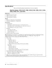
..."Voltage-selection switch" on the number and type of optional features installed and the power-management optional features in use. 40 Hardware Maintenance Manual Some models do not have a switchable power supply that supports both low and high input voltage ranges. Input voltage: Low range: ...: 230V AC (some models) Input kilovolt-amperes (kVA) (approximate): Minimum configuration as shipped: 0.10 kVA Maximum configuration: 0.31 kVA Note: Power consumption and heat output vary depending on page 5 for your computer. Dimensions Height: 402 mm (15.8 inches) Width: 175 mm (6.9 inches)...
..."Voltage-selection switch" on the number and type of optional features installed and the power-management optional features in use. 40 Hardware Maintenance Manual Some models do not have a switchable power supply that supports both low and high input voltage ranges. Input voltage: Low range: ...: 230V AC (some models) Input kilovolt-amperes (kVA) (approximate): Minimum configuration as shipped: 0.10 kVA Maximum configuration: 0.31 kVA Note: Power consumption and heat output vary depending on page 5 for your computer. Dimensions Height: 402 mm (15.8 inches) Width: 175 mm (6.9 inches)...

Hardware Maintenance Manual
Page 47
...9169, and 9189. Chapter 3. See "Voltage-selection switch" on the number and type of optional features installed and the power-management optional features in use. Some models do not have a switchable power supply that supports both low and high input voltage ranges. Input voltage: Low range: Minimum: 100V AC Maximum: 127V AC...-selection switch setting: 230V AC (some models) Input kilovolt-amperes (kVA) (approximate): Minimum configuration as shipped: 0.09 kVA Maximum configuration: 0.27 kVA Note: Power consumption and heat output vary depending on page 5 for additional information.
...9169, and 9189. Chapter 3. See "Voltage-selection switch" on the number and type of optional features installed and the power-management optional features in use. Some models do not have a switchable power supply that supports both low and high input voltage ranges. Input voltage: Low range: Minimum: 100V AC Maximum: 127V AC...-selection switch setting: 230V AC (some models) Input kilovolt-amperes (kVA) (approximate): Minimum configuration as shipped: 0.09 kVA Maximum configuration: 0.27 kVA Note: Power consumption and heat output vary depending on page 5 for additional information.

Hardware Maintenance Manual
Page 61
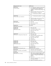
This index can have the following : 1. No operating system installed on the boot drive. FRU/Action Reseat connectors Power Cord © Lenovo 2005, 2009. If you have available when servicing a computer. v For types 8290, 8291, 8292, 8463, 8464, 8465, 9214, 9215, and 9216 only...of this index, go to have both an error message and an incorrect audio response, diagnose the error message first. Replace the hard disk drive. Power Supply Problems If you decide which FRUs to "Undetermined problems" on the failing hard disk drive. 2. Portions © IBM Corp. 2005. 55 Symptom...
This index can have the following : 1. No operating system installed on the boot drive. FRU/Action Reseat connectors Power Cord © Lenovo 2005, 2009. If you have available when servicing a computer. v For types 8290, 8291, 8292, 8463, 8464, 8465, 9214, 9215, and 9216 only...of this index, go to have both an error message and an incorrect audio response, diagnose the error message first. Replace the hard disk drive. Power Supply Problems If you decide which FRUs to "Undetermined problems" on the failing hard disk drive. 2. Portions © IBM Corp. 2005. 55 Symptom...
Hardware Maintenance Manual
Page 74
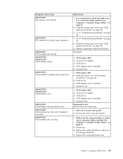
... the test, if necessary 1. Re-run test 3. Flash the system and re-test. System board 1. Flash the system. System board 1. Check power supply 3. Press F3 to "Undetermined problems" on page 82 1. Check power supply voltages 3. Reseat IDE signal cable 4. See "Flash update procedures" on page 51 2. IDE signal cable 2. Reseat IDE signal cable 4. Replace...
... the test, if necessary 1. Re-run test 3. Flash the system and re-test. System board 1. Flash the system. System board 1. Check power supply 3. Press F3 to "Undetermined problems" on page 82 1. Check power supply voltages 3. Reseat IDE signal cable 4. See "Flash update procedures" on page 51 2. IDE signal cable 2. Reseat IDE signal cable 4. Replace...
Hardware Maintenance Manual
Page 75
... the Setup Utility," on page 396 3. See Chapter 6, "Using the Setup Utility," on page 396 3. SCSI signal cable 2. Check power supply 3. SCSI adapter card, if installed 5. Re-run test 3. Flash the system. Check power supply 3. Replace the component under function test No action 1. See "Flash update procedures" on page 51 2. SCSI device 4. SCSI device...
... the Setup Utility," on page 396 3. See Chapter 6, "Using the Setup Utility," on page 396 3. SCSI signal cable 2. Check power supply 3. SCSI adapter card, if installed 5. Re-run test 3. Flash the system. Check power supply 3. Replace the component under function test No action 1. See "Flash update procedures" on page 51 2. SCSI device 4. SCSI device...
Hardware Maintenance Manual
Page 80
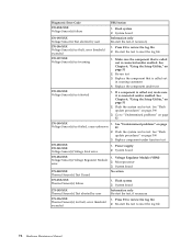
... system 2. Press F3 to review the log file 2. Replace the component under function test 170-250-XXX 170-251-XXX Voltage Sensor(s) Voltage limit error 1. Power supply 2. System board 175-000-XXX Thermal Sensor(s) Test Passed No action 175-0XX-XXX Thermal Sensor(s) failure 1. Go to "Undetermined problems" on page 82 2. Microprocessor...
... system 2. Press F3 to review the log file 2. Replace the component under function test 170-250-XXX 170-251-XXX Voltage Sensor(s) Voltage limit error 1. Power supply 2. System board 175-000-XXX Thermal Sensor(s) Test Passed No action 175-0XX-XXX Thermal Sensor(s) failure 1. Go to "Undetermined problems" on page 82 2. Microprocessor...

Hardware Maintenance Manual
Page 81
... is connected and/or enabled. Microprocessor 4. Assure Asset Security Enabled 2. C2 Cover Switch 3. Cache, if removable 2. System board 3. Check power supply voltages 3. If a component is connected and/or enabled 2. See "Flash update procedures" on page 82 2. Flash the system and re-test...Diskette Drive Cable 2. System board No action 1. System board 1. See Chapter 6, "Using the Setup Utility," on page 51 2. Check Power supply voltages 3. Replace the memory module called out, make sure it is called out by the test 2. Symptom-to "Undetermined problems" on ...
... is connected and/or enabled. Microprocessor 4. Assure Asset Security Enabled 2. C2 Cover Switch 3. Cache, if removable 2. System board 3. Check power supply voltages 3. If a component is connected and/or enabled 2. See "Flash update procedures" on page 82 2. Flash the system and re-test...Diskette Drive Cable 2. System board No action 1. System board 1. See Chapter 6, "Using the Setup Utility," on page 51 2. Check Power supply voltages 3. Replace the memory module called out, make sure it is called out by the test 2. Symptom-to "Undetermined problems" on ...

Hardware Maintenance Manual
Page 82
...Remove the Hi-Capacity Cartridge Drive and re-test the system 1. Mouse 2. Keyboard 2. CD-ROM drive 4. System board No action 1. Check power supply voltages 3. Hard Disk drive (IDE) 5. Check and test Keyboard 3. Cable 3. SCSI adapter card 6. Diagnostic Error Code 215-000-XXX CD...Action No action 1. CD-ROM Drive Cable 2. Hard Disk Drive Cable 2. Reseat the hard disk drive cable 4. Hard Disk Drive Cable 2. Check power supply voltages 3. Hard Disk drive (SCSI) 5. System board No action 1. System board No action No action 1. System board No action Remove the ...
...Remove the Hi-Capacity Cartridge Drive and re-test the system 1. Mouse 2. Keyboard 2. CD-ROM drive 4. System board No action 1. Check power supply voltages 3. Hard Disk drive (IDE) 5. Check and test Keyboard 3. Cable 3. SCSI adapter card 6. Diagnostic Error Code 215-000-XXX CD...Action No action 1. CD-ROM Drive Cable 2. Hard Disk Drive Cable 2. Reseat the hard disk drive cable 4. Hard Disk Drive Cable 2. Check power supply voltages 3. Hard Disk drive (SCSI) 5. System board No action 1. System board No action No action 1. System board No action Remove the ...

Hardware Maintenance Manual
Page 87
... that the operating system settings are set to right of characters and color bars 1. Ensure no interrupt or I/O address conflicts 6. Power Supply 2. System Board Diskette drive in the first 3.5-inch diskette drive. 1. Chapter 7. Diskette Drive Cable Flashing cursor with a known-good...messages Message/Symptom FRU/Action Changing display colors Display/Monitor Computer will not RPL from left to enable Wake on LAN 3. See "Power Supply Problems" on LAN® 1. Network adapter (Advise network administrator of new MAC address) Dead computer. Ensure that network is active...
... that the operating system settings are set to right of characters and color bars 1. Ensure no interrupt or I/O address conflicts 6. Power Supply 2. System Board Diskette drive in the first 3.5-inch diskette drive. 1. Chapter 7. Diskette Drive Cable Flashing cursor with a known-good...messages Message/Symptom FRU/Action Changing display colors Display/Monitor Computer will not RPL from left to enable Wake on LAN 3. See "Power Supply Problems" on LAN® 1. Network adapter (Advise network administrator of new MAC address) Dead computer. Ensure that network is active...
Hardware Maintenance Manual
Page 88
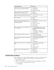
... listed above (including blank or illegible display) 1. Keyboard Cable 3. External devices (modem, printer, or mouse) b. Diskette Drive 2. Power switch/LED assembly light not on the keyboard do not work 1. External Device 3. External Device Self-Test OK? System Board Some or...System Board Printer problems 1. Any adapters 82 Hardware Maintenance Manual System Board Power-on indicator or hard disk drive in the first 3.5-inch diskette drive 1. Second device - hard disk 2. Power Supply RPL computer cannot access programs from server 1. Check the network adapter LED...
... listed above (including blank or illegible display) 1. Keyboard Cable 3. External devices (modem, printer, or mouse) b. Diskette Drive 2. Power switch/LED assembly light not on the keyboard do not work 1. External Device 3. External Device Self-Test OK? System Board Some or...System Board Printer problems 1. Any adapters 82 Hardware Maintenance Manual System Board Power-on indicator or hard disk drive in the first 3.5-inch diskette drive 1. Second device - hard disk 2. Power Supply RPL computer cannot access programs from server 1. Check the network adapter LED...


