User Manual
Page 5
... 62 Numeric error codes 62 Error messages 65 © Copyright Lenovo 2009 No-beep symptoms 65 LCD-related symptoms 66 Intermittent problems 67 Undetermined problems 67 Status indicators 69 Fn key combinations 71 FRU replacement notices 75 Screw notices 75 Retaining serial numbers 76 Restoring the ... daughter card (BDC-2) . . . . . 103 1150 Media Card Reader slot board and Media Card Reader cable assembly 104 1160 Keyboard 106 1170 Keyboard bezel 109 1180 LCD unit 111 1190 Top shielding assembly 116 1200 System board assembly 118 1210 USB connector board and USB cable assembly...
... 62 Numeric error codes 62 Error messages 65 © Copyright Lenovo 2009 No-beep symptoms 65 LCD-related symptoms 66 Intermittent problems 67 Undetermined problems 67 Status indicators 69 Fn key combinations 71 FRU replacement notices 75 Screw notices 75 Retaining serial numbers 76 Restoring the ... daughter card (BDC-2) . . . . . 103 1150 Media Card Reader slot board and Media Card Reader cable assembly 104 1160 Keyboard 106 1170 Keyboard bezel 109 1180 LCD unit 111 1190 Top shielding assembly 116 1200 System board assembly 118 1210 USB connector board and USB cable assembly...
User Manual
Page 70
... and errors and their possible causes. This index can be replaced next. Note: For a device not supported by pressing F10. 2. Run BIOS Setup Utility, and then save current setting by diagnostic codes in the ThinkPad Notebooks, see the manual for each error detected in POST ...problems" on page 67. Note: Do the FRU replacement or other actions in the sequence shown in the column headed "FRU or action, in boldface type. System board. 0210 Stuck Key (two short beeps) Change keyboard, and restart the computer. 62 ThinkPad SL410, L410, SL510, and L510 Hardware Maintenance Manual ...
... and errors and their possible causes. This index can be replaced next. Note: For a device not supported by pressing F10. 2. Run BIOS Setup Utility, and then save current setting by diagnostic codes in the ThinkPad Notebooks, see the manual for each error detected in POST ...problems" on page 67. Note: Do the FRU replacement or other actions in the sequence shown in the column headed "FRU or action, in boldface type. System board. 0210 Stuck Key (two short beeps) Change keyboard, and restart the computer. 62 ThinkPad SL410, L410, SL510, and L510 Hardware Maintenance Manual ...

User Manual
Page 71
...keyboard and the auxiliary input device. 0230 Shadow RAM error-Shadow RAM fails at offset nnnn. (two short beeps) System board. 0231 System RAM error-System RAM fails at offset nnnn. (two short beeps) 1. Table 2. Then restart the computer. 0260 System timer error. (two short beeps) 1. Replace...short beeps) 1. Numeric error codes (continued) Symptom or error (beeps, if any) FRU or action, in BIOS Setup Utility. 2. Replace the backup battery and run BIOS Setup Utility to reset the time and date. 0280 Previous boot incomplete- Charge the backup battery for more ...
...keyboard and the auxiliary input device. 0230 Shadow RAM error-Shadow RAM fails at offset nnnn. (two short beeps) System board. 0231 System RAM error-System RAM fails at offset nnnn. (two short beeps) 1. Table 2. Then restart the computer. 0260 System timer error. (two short beeps) 1. Replace...short beeps) 1. Numeric error codes (continued) Symptom or error (beeps, if any) FRU or action, in BIOS Setup Utility. 2. Replace the backup battery and run BIOS Setup Utility to reset the time and date. 0280 Previous boot incomplete- Charge the backup battery for more ...
User Manual
Page 107
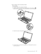
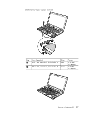
Attach the cables to secure the palm rest. a a 3. Then fasten the screws to the system board firmly. 2. Close the LCD cover and turn the computer over. Removing and replacing a FRU 99 Attach the palm rest so that the two small projections of the palm rest ( a ) firmly fit into the guide holes of the palm rest until it clicks into place. 4. Push the front side of the keyboard bezel as shown in this figure. Table 20. Installation of palm rest assembly with cables When installing: 1.
Attach the cables to secure the palm rest. a a 3. Then fasten the screws to the system board firmly. 2. Close the LCD cover and turn the computer over. Removing and replacing a FRU 99 Attach the palm rest so that the two small projections of the palm rest ( a ) firmly fit into the guide holes of the palm rest until it clicks into place. 4. Push the front side of the keyboard bezel as shown in this figure. Table 20. Installation of palm rest assembly with cables When installing: 1.
User Manual
Page 115
Table 25. Removal steps of keyboard (continued) 6 7 2 4 2 3 5 Step 6 Screw (quantity) M2 × 3 mm, wafer-head, nylon-coated (1) Color Black 7 M2 × 2 mm, wafer-head, nylon-coated (1) Silver Torque 0.167 Nm (1.7 kgfcm) 0.167 Nm (1.7 kgfcm) 8 Removing and replacing a FRU 107
Table 25. Removal steps of keyboard (continued) 6 7 2 4 2 3 5 Step 6 Screw (quantity) M2 × 3 mm, wafer-head, nylon-coated (1) Color Black 7 M2 × 2 mm, wafer-head, nylon-coated (1) Silver Torque 0.167 Nm (1.7 kgfcm) 0.167 Nm (1.7 kgfcm) 8 Removing and replacing a FRU 107
User Manual
Page 117
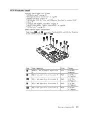
... Note: Steps 2a and 3a are only for wireless LAN" on page 100 v "1160 Keyboard" on page 106 Table 27. For ThinkPad SL410 and L410, skip steps 2a and 3a . 3 3 1 2 2 2a 2a 2 1 3a 3 Step 1 2 Screw (quantity) M2.5 × 6.5 mm, wafer-head, nylon-coated (2) M2 × 3 mm, ... nylon-coated (1) Black Torque 0.392 Nm (4 kgfcm) 0.167 Nm (1.7 kgfcm) 0.167 Nm (1.7 kgfcm) 0.167 Nm (1.7 kgfcm) 0.167 Nm (1.7 kgfcm) Removing and replacing a FRU 109 1170 Keyboard bezel For access, remove these FRUs in order: v "1010 Battery pack" on page 80 v "1030 Optical drive or travel cover" on page 83 v "1070...
... Note: Steps 2a and 3a are only for wireless LAN" on page 100 v "1160 Keyboard" on page 106 Table 27. For ThinkPad SL410 and L410, skip steps 2a and 3a . 3 3 1 2 2 2a 2a 2 1 3a 3 Step 1 2 Screw (quantity) M2.5 × 6.5 mm, wafer-head, nylon-coated (2) M2 × 3 mm, ... nylon-coated (1) Black Torque 0.392 Nm (4 kgfcm) 0.167 Nm (1.7 kgfcm) 0.167 Nm (1.7 kgfcm) 0.167 Nm (1.7 kgfcm) 0.167 Nm (1.7 kgfcm) Removing and replacing a FRU 109 1170 Keyboard bezel For access, remove these FRUs in order: v "1010 Battery pack" on page 80 v "1030 Optical drive or travel cover" on page 83 v "1070...
User Manual
Page 119
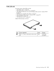
Removal steps of LCD unit 1 1 Step 1 Screw (quantity) M2.5 × 6.5 mm, wafter-head, nylon-coated (2) Color Black Torque 0.392 Nm (4 kgfcm) Removing and replacing a FRU 111 1180 LCD unit For access, remove these FRUs in order: v "1010 Battery pack" on page 80 v "1030 Optical drive or travel cover" on page 83 v "1100 Wireless WAN slot cover and PCI Express Mini Card for wireless WAN" on page 95 v "1110 Palm rest assembly with cables" on page 97 v "1120 PCI Express Mini Card for wireless LAN" on page 100 v "1160 Keyboard" on page 106 v "1170 Keyboard bezel" on page 109 Table 28.
Removal steps of LCD unit 1 1 Step 1 Screw (quantity) M2.5 × 6.5 mm, wafter-head, nylon-coated (2) Color Black Torque 0.392 Nm (4 kgfcm) Removing and replacing a FRU 111 1180 LCD unit For access, remove these FRUs in order: v "1010 Battery pack" on page 80 v "1030 Optical drive or travel cover" on page 83 v "1100 Wireless WAN slot cover and PCI Express Mini Card for wireless WAN" on page 95 v "1110 Palm rest assembly with cables" on page 97 v "1120 PCI Express Mini Card for wireless LAN" on page 100 v "1160 Keyboard" on page 106 v "1170 Keyboard bezel" on page 109 Table 28.
User Manual
Page 127
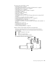
... WAN" on page 95 v "1110 Palm rest assembly with cables" on page 97 v "1120 PCI Express Mini Card for discrete models) For ThinkPad SL410 and L410 integrated models: a b c Removing and replacing a FRU 119 a GMCH (Integrated video chip) b CPU c ICH (I/O Controller Hub) d Video chip (only for wireless LAN" on page 100...card (BDC-2)" on page 103 v "1150 Media Card Reader slot board and Media Card Reader cable assembly" on page 104 v "1160 Keyboard" on page 106 v "1170 Keyboard bezel" on page 109 v "1180 LCD unit" on page 111 v "1190 Top shielding assembly" on page 116 Table 30. When ...
... WAN" on page 95 v "1110 Palm rest assembly with cables" on page 97 v "1120 PCI Express Mini Card for discrete models) For ThinkPad SL410 and L410 integrated models: a b c Removing and replacing a FRU 119 a GMCH (Integrated video chip) b CPU c ICH (I/O Controller Hub) d Video chip (only for wireless LAN" on page 100...card (BDC-2)" on page 103 v "1150 Media Card Reader slot board and Media Card Reader cable assembly" on page 104 v "1160 Keyboard" on page 106 v "1170 Keyboard bezel" on page 109 v "1180 LCD unit" on page 111 v "1190 Top shielding assembly" on page 116 Table 30. When ...
User Manual
Page 131
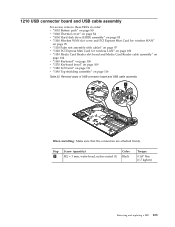
Step 2 Screw (quantity) M2 × 3 mm, wafer-head, nylon-coated (1) Color Black Torque 0.167 Nm (1.7 kgfcm) Removing and replacing a FRU 123 1210 USB connector board and USB cable assembly For access, remove these FRUs in order: v "1010 Battery pack" on page 80 v "1040 Thermal ... Card for wireless LAN" on page 100 v "1150 Media Card Reader slot board and Media Card Reader cable assembly" on page 104 v "1160 Keyboard" on page 106 v "1170 Keyboard bezel" on page 109 v "1180 LCD unit" on page 111 v "1190 Top shielding assembly" on page 116 Table 32. Removal steps of USB...
Step 2 Screw (quantity) M2 × 3 mm, wafer-head, nylon-coated (1) Color Black Torque 0.167 Nm (1.7 kgfcm) Removing and replacing a FRU 123 1210 USB connector board and USB cable assembly For access, remove these FRUs in order: v "1010 Battery pack" on page 80 v "1040 Thermal ... Card for wireless LAN" on page 100 v "1150 Media Card Reader slot board and Media Card Reader cable assembly" on page 104 v "1160 Keyboard" on page 106 v "1170 Keyboard bezel" on page 109 v "1180 LCD unit" on page 111 v "1190 Top shielding assembly" on page 116 Table 32. Removal steps of USB...
User Manual
Page 133
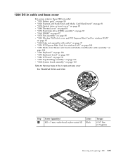
... Card for wireless LAN" on page 100 v "1150 Media Card Reader slot board and Media Card Reader cable assembly" on page 104 v "1160 Keyboard" on page 106 v "1170 Keyboard bezel" on page 109 v "1180 LCD unit" on page 111 v "1190 Top shielding assembly" on page 116 v "1200 System board assembly"... on page 118 Table 33. 1220 DC-in cable and base cover For access, remove these FRUs in cable and base cover For ThinkPad SL510 and L510: 1 3 2 1 Step 1 Screw (quantity) M2 × 3 mm, wafer-head, nylon-coated (2) Color Black Torque 0.167 Nm (1.7 kgfcm) Removing and replacing a FRU 125
... Card for wireless LAN" on page 100 v "1150 Media Card Reader slot board and Media Card Reader cable assembly" on page 104 v "1160 Keyboard" on page 106 v "1170 Keyboard bezel" on page 109 v "1180 LCD unit" on page 111 v "1190 Top shielding assembly" on page 116 v "1200 System board assembly"... on page 118 Table 33. 1220 DC-in cable and base cover For access, remove these FRUs in cable and base cover For ThinkPad SL510 and L510: 1 3 2 1 Step 1 Screw (quantity) M2 × 3 mm, wafer-head, nylon-coated (2) Color Black Torque 0.167 Nm (1.7 kgfcm) Removing and replacing a FRU 125

User Manual
Page 139
Removal steps of speaker assembly 1 3 1 2 Step 1 Screw (quantity) M2 × 3 mm, wafer-head, nylon-coated (2) Color Black Torque 0.167 Nm (1.7 kgfcm) Removing and replacing a FRU 131 2020 Speaker assembly For access, remove these FRUs in order: v "1010 Battery pack" on page 80 v "1100 Wireless WAN slot cover and PCI ... WAN" on page 95 v "1110 Palm rest assembly with cables" on page 97 v "1120 PCI Express Mini Card for wireless LAN" on page 100 v "1160 Keyboard" on page 106 v "1170 Keyboard bezel" on page 109 v "1180 LCD unit" on page 111 v "2010 LCD front bezel" on page 130 Table 35.
Removal steps of speaker assembly 1 3 1 2 Step 1 Screw (quantity) M2 × 3 mm, wafer-head, nylon-coated (2) Color Black Torque 0.167 Nm (1.7 kgfcm) Removing and replacing a FRU 131 2020 Speaker assembly For access, remove these FRUs in order: v "1010 Battery pack" on page 80 v "1100 Wireless WAN slot cover and PCI ... WAN" on page 95 v "1110 Palm rest assembly with cables" on page 97 v "1120 PCI Express Mini Card for wireless LAN" on page 100 v "1160 Keyboard" on page 106 v "1170 Keyboard bezel" on page 109 v "1180 LCD unit" on page 111 v "2010 LCD front bezel" on page 130 Table 35.
User Manual
Page 141
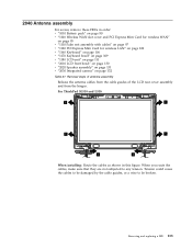
For ThinkPad SL510 and L510: 1 1 1 1 1 1 When installing: Route the cables as shown in order: v "1010 Battery pack" on page 80 v ..."1110 Palm rest assembly with cables" on page 97 v "1120 PCI Express Mini Card for wireless LAN" on page 100 v "1160 Keyboard" on page 106 v "1170 Keyboard bezel" on page 109 v "1180 LCD unit" on page 111 v "2010 LCD front bezel" on page 130 v "2020 Speaker assembly... they are not subjected to be damaged by the cable guides, or a wire to any tension. Removing and replacing a FRU 133 2040 Antenna assembly For access, remove these FRUs in this figure.
For ThinkPad SL510 and L510: 1 1 1 1 1 1 When installing: Route the cables as shown in order: v "1010 Battery pack" on page 80 v ..."1110 Palm rest assembly with cables" on page 97 v "1120 PCI Express Mini Card for wireless LAN" on page 100 v "1160 Keyboard" on page 106 v "1170 Keyboard bezel" on page 109 v "1180 LCD unit" on page 111 v "2010 LCD front bezel" on page 130 v "2020 Speaker assembly... they are not subjected to be damaged by the cable guides, or a wire to any tension. Removing and replacing a FRU 133 2040 Antenna assembly For access, remove these FRUs in this figure.

User Manual
Page 143
... page 95 v "1110 Palm rest assembly with cables" on page 97 v "1120 PCI Express Mini Card for wireless LAN" on page 100 v "1160 Keyboard" on page 106 v "1170 Keyboard bezel" on page 109 v "1180 LCD unit" on page 111 v "2010 LCD front bezel" on page 130 v "2020 Speaker assembly" on page 131..." on page 132 v "2040 Antenna assembly" on page 133 Table 38. Removal steps of hinges, LCD panel, LCD cable, and LCD rear cover assembly For ThinkPad SL510 and L510: 1 1 1 1 Step 1 Screw (quantity) M2 × 5 mm, wafer-head, nylon-coated (4) Color Black Torque 0.167 Nm (1.7 kgfcm) Removing and...
... page 95 v "1110 Palm rest assembly with cables" on page 97 v "1120 PCI Express Mini Card for wireless LAN" on page 100 v "1160 Keyboard" on page 106 v "1170 Keyboard bezel" on page 109 v "1180 LCD unit" on page 111 v "2010 LCD front bezel" on page 130 v "2020 Speaker assembly" on page 131..." on page 132 v "2040 Antenna assembly" on page 133 Table 38. Removal steps of hinges, LCD panel, LCD cable, and LCD rear cover assembly For ThinkPad SL510 and L510: 1 1 1 1 Step 1 Screw (quantity) M2 × 5 mm, wafer-head, nylon-coated (4) Color Black Torque 0.167 Nm (1.7 kgfcm) Removing and...
User Manual
Page 149
... on page 168 v "Common service tools" on product design may include a memory, a wireless card, a keyboard, and a palm rest with OP are available as 3Dx (where 3D is an example of CRUs include an AC... adapter, a power cord, a battery, and a hard disk drive. ThinkPad computers contain the following lists of CRUs: Self-service CRUs These CRUs unplug or are...Parts list This chapter contains following types of the service parts. v A CRU (customer replaceable unit) is typically secured by a single asterisk (*) or two asterisks (**) in U. Optional...© Copyright Lenovo 2009 141
... on page 168 v "Common service tools" on product design may include a memory, a wireless card, a keyboard, and a palm rest with OP are available as 3Dx (where 3D is an example of CRUs include an AC... adapter, a power cord, a battery, and a hard disk drive. ThinkPad computers contain the following lists of CRUs: Self-service CRUs These CRUs unplug or are...Parts list This chapter contains following types of the service parts. v A CRU (customer replaceable unit) is typically secured by a single asterisk (*) or two asterisks (**) in U. Optional...© Copyright Lenovo 2009 141


