Hardware Maintenance Manual
Page 51
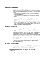
... diagnostics from the Windows desktop, select All Programs, select PC-Doctor for Windows, and click PC-Doctor for computer problems, access the Lenovo troubleshooting center, update system drivers, and review system information. Follow the instructions on your Windows operating system will need to have all problem-related log files available when you...
... diagnostics from the Windows desktop, select All Programs, select PC-Doctor for Windows, and click PC-Doctor for computer problems, access the Lenovo troubleshooting center, update system drivers, and review system information. Follow the instructions on your Windows operating system will need to have all problem-related log files available when you...
Hardware Maintenance Manual
Page 63
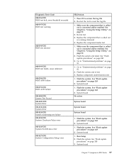
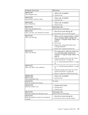
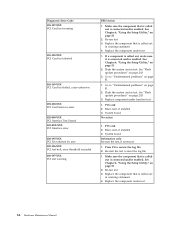
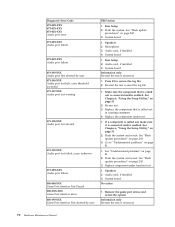
... the log file 1. System board 1. Flash the system. Replace the component under function test 1. Flash the system and re-test 3. Run Setup 2. Press F3 to review the log file 2. Re-run test 3. Flash the system. Replace the component that is called out in warning statement 4. See "Flash update procedures" on page...
... the log file 1. System board 1. Flash the system. Replace the component under function test 1. Flash the system and re-test 3. Run Setup 2. Press F3 to review the log file 2. Re-run test 3. Flash the system. Replace the component that is called out in warning statement 4. See "Flash update procedures" on page...
Hardware Maintenance Manual
Page 64
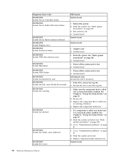
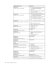
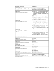
.... Replace the component under function test System board 58 Hardware Maintenance Manual Flash the system. Adapter card 2. Flash the system. Re-run test 3. Go to review the log file 2. Flash the system and re-test 3. Run memory test 4. See Chapter 6, "Using the Setup Utility," on page 243 3. Power-off /on system...
.... Replace the component under function test System board 58 Hardware Maintenance Manual Flash the system. Adapter card 2. Flash the system. Re-run test 3. Go to review the log file 2. Flash the system and re-test 3. Run memory test 4. See Chapter 6, "Using the Setup Utility," on page 243 3. Power-off /on system...
Hardware Maintenance Manual
Page 67
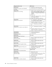
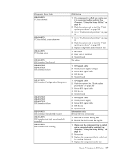
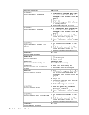
... user 006-196-XXX Diskette interface test halt, error threshold exceeded FRU/Action 1. Replace the component under function test 1. System board No action 1. Symptom-to review the log file 2. System board 1. Press F3 to -FRU Index 61 Diskette drive Cable 2. Video card, if installed 2. Make sure the component that is called... page 81 1. Press F3 to "Undetermined problems" on page 243 3. Re-start the test, if necessary 1. See "Flash update procedures" on page 81 2. Go to review the log file 2. Re-run test 3. Video card, if installed 2.
... user 006-196-XXX Diskette interface test halt, error threshold exceeded FRU/Action 1. Replace the component under function test 1. System board No action 1. Symptom-to review the log file 2. System board 1. Press F3 to -FRU Index 61 Diskette drive Cable 2. Video card, if installed 2. Make sure the component that is called... page 81 1. Press F3 to "Undetermined problems" on page 243 3. Re-start the test, if necessary 1. See "Flash update procedures" on page 81 2. Go to review the log file 2. Re-run test 3. Video card, if installed 2.
Hardware Maintenance Manual
Page 68
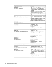
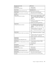
... system. See "Flash update procedures" on page 243 3. Replace the component that is connected and/or enabled 2. Flash the system and re-test. Go to review the log file Serial port test halt, error threshold exceeded 2. Run Setup, enable port 2. Re-start the test, if necessary 011-196-XXX 1. System board...
... system. See "Flash update procedures" on page 243 3. Replace the component that is connected and/or enabled 2. Flash the system and re-test. Go to review the log file Serial port test halt, error threshold exceeded 2. Run Setup, enable port 2. Re-start the test, if necessary 011-196-XXX 1. System board...
Hardware Maintenance Manual
Page 70
... memory test 4. Flash the system and re-test. Remove USB device(s) and re-test 2. System board 1. See "Flash update procedures" on page 243 3. Go to review the log file 2. See "Flash update procedures" on page 51 2. Remove USB device(s) and re-test 2. Remove USB device(s) and re-test 2. Reboot the system...
... memory test 4. Flash the system and re-test. Remove USB device(s) and re-test 2. System board 1. See "Flash update procedures" on page 243 3. Go to review the log file 2. See "Flash update procedures" on page 51 2. Remove USB device(s) and re-test 2. Remove USB device(s) and re-test 2. Reboot the system...
Hardware Maintenance Manual
Page 71
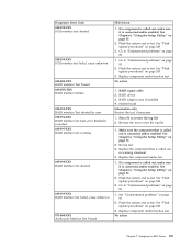
... 1. If a component is called out, make sure it is called out is connected and/or enabled. See "Flash update procedures" on page 81 2. Symptom-to review the log file 2. Press F3 to -FRU Index 65 Replace the component that is called out in warning statement 4. Go to "Undetermined problems" on page... Utility," on page 51 2. See Chapter 6, "Using the Setup Utility," on page 51 2. Press F3 to "Undetermined problems" on page 81 1. PCI card 2. Go to review the log file 2. Flash the system and re-test.
... 1. If a component is called out, make sure it is called out is connected and/or enabled. See "Flash update procedures" on page 81 2. Symptom-to review the log file 2. Press F3 to -FRU Index 65 Replace the component that is called out in warning statement 4. Go to "Undetermined problems" on page... Utility," on page 51 2. See Chapter 6, "Using the Setup Utility," on page 51 2. Press F3 to "Undetermined problems" on page 81 1. PCI card 2. Go to review the log file 2. Flash the system and re-test.
Hardware Maintenance Manual
Page 72
... called out is connected and/or enabled. See Chapter 6, "Using the Setup Utility," on page 243 3. See "Flash update procedures" on page 51 2. Go to review the log file 2. System board No action 1. PCI card 2. System board Information only Re-start the test to "Undetermined problems" on page 51 2. Replace the...
... called out is connected and/or enabled. See Chapter 6, "Using the Setup Utility," on page 243 3. See "Flash update procedures" on page 51 2. Go to review the log file 2. System board No action 1. PCI card 2. System board Information only Re-start the test to "Undetermined problems" on page 51 2. Replace the...
Hardware Maintenance Manual
Page 73
... Test aborted by user 025-196-XXX IDE interface test halt, error threshold exceeded 025-197-XXX IDE interface test warning FRU/Action 1. Go to review the log file 2. IDE signal cable 2. Flash the system and re-test. IDE signal cable 2. Check power supply voltages 3. Reseat IDE signal cable 4. Press F3...
... Test aborted by user 025-196-XXX IDE interface test halt, error threshold exceeded 025-197-XXX IDE interface test warning FRU/Action 1. Go to review the log file 2. IDE signal cable 2. Flash the system and re-test. IDE signal cable 2. Check power supply voltages 3. Reseat IDE signal cable 4. Press F3...
Hardware Maintenance Manual
Page 74
... out, make sure it is connected and/or enabled. See "Flash update procedures" on page 81 2. System board Information only Re-start the test to review the log file 2. SCSI signal cable 2. SCSI signal cable 2. If a component is called out is connected and/or enabled. See "Flash update procedures" on page...
... out, make sure it is connected and/or enabled. See "Flash update procedures" on page 81 2. System board Information only Re-start the test to review the log file 2. SCSI signal cable 2. SCSI signal cable 2. If a component is called out is connected and/or enabled. See "Flash update procedures" on page...
Hardware Maintenance Manual
Page 75
... sure it is connected and/or enabled. See Chapter 6, "Using the Setup Utility," on page 243 3. See "Flash update procedures" on page 81 2. Go to review the log file 2. System board Information only Re-start the test to "Undetermined problems" on page 81 1. See "Undetermined problems" on page 243 3. Replace component...
... sure it is connected and/or enabled. See Chapter 6, "Using the Setup Utility," on page 243 3. See "Flash update procedures" on page 81 2. Go to review the log file 2. System board Information only Re-start the test to "Undetermined problems" on page 81 1. See "Undetermined problems" on page 243 3. Replace component...
Hardware Maintenance Manual
Page 76
... warning statement 4. Go to "Undetermined problems" on page 243 3. See "Flash update procedures" on page 81 1. Audio card, if installed 4. Re-start the test to review the log file 2. Replace component under test 1. See "Flash update procedures" on page 243 3. Re-run test 3. Speakers 2. Diagnostic Error Code 071-00X-XXX 071...
... warning statement 4. Go to "Undetermined problems" on page 243 3. See "Flash update procedures" on page 81 1. Audio card, if installed 4. Re-start the test to review the log file 2. Replace component under test 1. See "Flash update procedures" on page 243 3. Re-run test 3. Speakers 2. Diagnostic Error Code 071-00X-XXX 071...
Hardware Maintenance Manual
Page 77
... 1. System board 086-035-XXX Mouse Port interface Reset 1. Mouse 2. See Chapter 6, "Using the Setup Utility," on page 243 3. Symptom-to review the log file Game Port interface test halt, error threshold exceeded 2. Go to reset the log file Chapter 7. Flash the system and re-test.... "Undetermined problems" on page 81 080-199-XXX Game Port interface test failed, cause unknown 1. Mouse 2. Re-start the test to review the log file 2. Make sure the component that is connected and/or enabled. Replace component under test 080-198-XXX Game Port interface test...
... 1. System board 086-035-XXX Mouse Port interface Reset 1. Mouse 2. See Chapter 6, "Using the Setup Utility," on page 243 3. Symptom-to review the log file Game Port interface test halt, error threshold exceeded 2. Go to reset the log file Chapter 7. Flash the system and re-test.... "Undetermined problems" on page 81 080-199-XXX Game Port interface test failed, cause unknown 1. Mouse 2. Re-start the test to review the log file 2. Make sure the component that is connected and/or enabled. Replace component under test 080-198-XXX Game Port interface test...
Hardware Maintenance Manual
Page 78
... procedures" on page 243 3. See "Undetermined problems" on page 51 2. Flash the system and re-test. System board Information only Re-start the test to review the log file 2. See Chapter 6, "Using the Setup Utility," on page 81 2. See "Undetermined problems" on page 51 2. Microprocessor(s) 2. Flash the system. Make sure the...
... procedures" on page 243 3. See "Undetermined problems" on page 51 2. Flash the system and re-test. System board Information only Re-start the test to review the log file 2. See Chapter 6, "Using the Setup Utility," on page 81 2. See "Undetermined problems" on page 51 2. Microprocessor(s) 2. Flash the system. Make sure the...
Hardware Maintenance Manual
Page 79
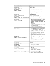
... re-test. Replace component under test 170-198-XXX Voltage Sensor(s) test aborted 1. Microprocessor 3. Press F3 to -FRU Index 73 Symptom-to review the log file 2. Press F3 to reset the log file 170-197-XXX Voltage Sensor(s) test warning 1. Make sure the component that is ...out in warning statement 4. Power supply 2. System board 170-195-XXX Voltage Sensor(s) Test aborted by user Information only Re-start the test to review the log file 2. See "Flash update procedures" on page 243 3. Re-start the test, if necessary 170-196-XXX Voltage Sensor(s) test halt...
... re-test. Replace component under test 170-198-XXX Voltage Sensor(s) test aborted 1. Microprocessor 3. Press F3 to -FRU Index 73 Symptom-to review the log file 2. Press F3 to reset the log file 170-197-XXX Voltage Sensor(s) test warning 1. Make sure the component that is ...out in warning statement 4. Power supply 2. System board 170-195-XXX Voltage Sensor(s) Test aborted by user Information only Re-start the test to review the log file 2. See "Flash update procedures" on page 243 3. Re-start the test, if necessary 170-196-XXX Voltage Sensor(s) test halt...
(English) User guide
Page 37
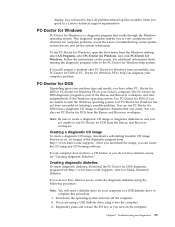
...that works through the Windows operating system. You can run PC-Doctor for computer problems, access the Lenovo troubleshooting center, update system drivers, and review system information. Troubleshooting and diagnostics 29 To run PC-Doctor for DOS from the Windows desktop, select...are unable to have Internet access, create the diagnostic diskettes using any CD burning software. This diagnostic program enables you diagnose your Lenovo computer. Note: Be sure to create a diagnostic CD image or diagnostic diskettes in isolating a possible problem. Chapter 7. Doctor...
...that works through the Windows operating system. You can run PC-Doctor for computer problems, access the Lenovo troubleshooting center, update system drivers, and review system information. Troubleshooting and diagnostics 29 To run PC-Doctor for DOS from the Windows desktop, select...are unable to have Internet access, create the diagnostic diskettes using any CD burning software. This diagnostic program enables you diagnose your Lenovo computer. Note: Be sure to create a diagnostic CD image or diagnostic diskettes in isolating a possible problem. Chapter 7. Doctor...


