

Hardware Maintenance Manual
Page 11
... are not sure of features or options not covered by this inspection guide is to assist you have verified that country or region. v Do not touch live electrical circuits with a voltage-selection switch located near the power-cord connection point on when they are moist floors, nongrounded power extension cables, power.... If your computer has a voltage-selection switch, ensure that the voltage provided is conductive; Pumps - Examples of the units.) v If an electrical accident occurs: - such touching can cause permanent damage to get medical aid.
... are not sure of features or options not covered by this inspection guide is to assist you have verified that country or region. v Do not touch live electrical circuits with a voltage-selection switch located near the power-cord connection point on when they are moist floors, nongrounded power extension cables, power.... If your computer has a voltage-selection switch, ensure that the voltage provided is conductive; Pumps - Examples of the units.) v If an electrical accident occurs: - such touching can cause permanent damage to get medical aid.
Hardware Maintenance Manual
Page 13
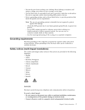
... danger safety notices in the following languages: v English v Arabic v Brazilian/Portuguese v Chinese (simplified) v Chinese (traditional) v French v German v Hebrew v Italian v Korean v Spanish DANGER Electrical current from touching your clothing. To avoid a shock hazard: v Do not connect or disconnect any frame ground, ground braid, or green-wire ground. - Attach the ESD ground clip...
... danger safety notices in the following languages: v English v Arabic v Brazilian/Portuguese v Chinese (simplified) v Chinese (traditional) v French v German v Hebrew v Italian v Korean v Spanish DANGER Electrical current from touching your clothing. To avoid a shock hazard: v Do not connect or disconnect any frame ground, ground braid, or green-wire ground. - Attach the ESD ground clip...
Hardware Maintenance Manual
Page 107
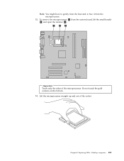
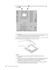
Note: You might have to gently twist the heat sink to free it from the system board, lift the small handle 3 and open the retainer 1 . Important Touch only the sides of the socket. Chapter 8. Desktop computers 101 Do not touch the gold contacts on the bottom. 14. Lift the microprocessor straight up and out of the microprocessor. Replacing FRUs - To remove the microprocessor 2 from the microprocessor. 13.
Note: You might have to gently twist the heat sink to free it from the system board, lift the small handle 3 and open the retainer 1 . Important Touch only the sides of the socket. Chapter 8. Desktop computers 101 Do not touch the gold contacts on the bottom. 14. Lift the microprocessor straight up and out of the microprocessor. Replacing FRUs - To remove the microprocessor 2 from the microprocessor. 13.
Hardware Maintenance Manual
Page 115
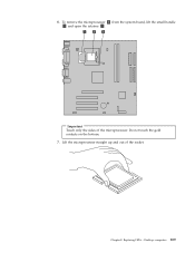
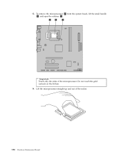
Important Touch only the sides of the socket. Lift the microprocessor straight up and out of the microprocessor. Desktop computers 109 Chapter 8. Replacing FRUs - Do not touch the gold contacts on the bottom. 7. To remove the microprocessor 2 from the system board, lift the small handle 3 and open the retainer 1 . 6.
Important Touch only the sides of the socket. Lift the microprocessor straight up and out of the microprocessor. Desktop computers 109 Chapter 8. Replacing FRUs - Do not touch the gold contacts on the bottom. 7. To remove the microprocessor 2 from the system board, lift the small handle 3 and open the retainer 1 . 6.
Hardware Maintenance Manual
Page 119
... until it snaps into position. 12. Desktop computers 113 Connect the signal and power cables to "Completing the FRU replacement" on page 120. Do not touch the circuit board 5 on each side of the hard disk drive. 8. 6. Install the new drive into position. 10. Reinstall the front bezel. 13. Replacing FRUs...
... until it snaps into position. 12. Desktop computers 113 Connect the signal and power cables to "Completing the FRU replacement" on page 120. Do not touch the circuit board 5 on each side of the hard disk drive. 8. 6. Install the new drive into position. 10. Reinstall the front bezel. 13. Replacing FRUs...
Hardware Maintenance Manual
Page 138
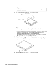
.... Your microprocessor and socket might look different than the one corner of the microprocessor. Make sure that the small triangle 1 on the bottom. 15. Important Touch only the sides of the microprocessor. Do not touch the gold contacts on one corner is in the socket.
.... Your microprocessor and socket might look different than the one corner of the microprocessor. Make sure that the small triangle 1 on the bottom. 15. Important Touch only the sides of the microprocessor. Do not touch the gold contacts on one corner is in the socket.
Hardware Maintenance Manual
Page 142
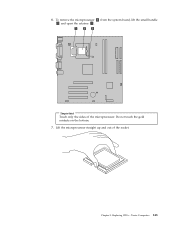
Lift the microprocessor straight up and out of the microprocessor. 13. Important Touch only the sides of the socket. 136 Hardware Maintenance Manual Do not touch the gold contacts on the bottom. 14. To remove the microprocessor 2 from the system board, lift the small handle 3 and open the retainer 1 .
Lift the microprocessor straight up and out of the microprocessor. 13. Important Touch only the sides of the socket. 136 Hardware Maintenance Manual Do not touch the gold contacts on the bottom. 14. To remove the microprocessor 2 from the system board, lift the small handle 3 and open the retainer 1 .
Hardware Maintenance Manual
Page 146
... the microprocessor. This is exposed. Look for the small triangle on the bottom of the socket. Important Do not touch the gold contacts on one illustrated. The socket pins must touch the microprocessor, touch only the sides. 7. Note the orientation of the microprocessor. If you must be kept as clean as possible. 140...
... the microprocessor. This is exposed. Look for the small triangle on the bottom of the socket. Important Do not touch the gold contacts on one illustrated. The socket pins must touch the microprocessor, touch only the sides. 7. Note the orientation of the microprocessor. If you must be kept as clean as possible. 140...
Hardware Maintenance Manual
Page 149
Important Touch only the sides of the socket. Replacing FRUs - Do not touch the gold contacts on the bottom. 7. Tower Computers 143 Lift the microprocessor straight up and out of the microprocessor. 6. Chapter 9. To remove the microprocessor 2 from the system board, lift the small handle 3 and open the retainer 1 .
Important Touch only the sides of the socket. Replacing FRUs - Do not touch the gold contacts on the bottom. 7. Tower Computers 143 Lift the microprocessor straight up and out of the microprocessor. 6. Chapter 9. To remove the microprocessor 2 from the system board, lift the small handle 3 and open the retainer 1 .
Hardware Maintenance Manual
Page 157
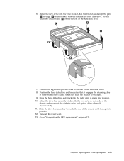
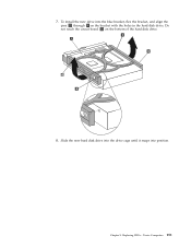
7. Do not touch the circuit board 5 on the bracket with the holes in the hard disk drive. Slide the new hard disk drive into the drive cage until it snaps into the blue bracket, flex the bracket, and align the pins 1 through 4 on the bottom of the hard disk drive. 8. Replacing FRUs - Chapter 9. Tower Computers 151 To install the new drive into position.
7. Do not touch the circuit board 5 on the bracket with the holes in the hard disk drive. Slide the new hard disk drive into the drive cage until it snaps into the blue bracket, flex the bracket, and align the pins 1 through 4 on the bottom of the hard disk drive. 8. Replacing FRUs - Chapter 9. Tower Computers 151 To install the new drive into position.
(English) User guide
Page 11
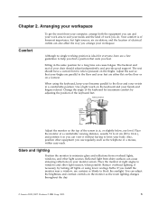
... so you can also affect the way you install the monitor near a window, use regularly, such as the room lighting changes throughout the day. © Lenovo 2005, 2007. Change the angle of electrical outlets can view it without having to suit your feet are a few guidelines to 24 in the same... and your chair should have a curved front to windows and other equipment you use and your work area to twist your monitor screen. Use a light touch on your body. Place the monitor at , or slightly below, eye level.
... so you can also affect the way you install the monitor near a window, use regularly, such as the room lighting changes throughout the day. © Lenovo 2005, 2007. Change the angle of electrical outlets can view it without having to suit your feet are a few guidelines to 24 in the same... and your chair should have a curved front to windows and other equipment you use and your work area to twist your monitor screen. Use a light touch on your body. Place the monitor at , or slightly below, eye level.
(English) User guide
Page 53
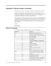
.... Switch from a command that requires one of the four telephone numbers (n=0-3) stored in Command Mode until you omit a parameter from Data Mode to Command Mode (T.I.E.S. touch-tone dialing wait for second dial tone pause wait for five seconds of 0. If you dial a number and establish a connection. Commands are accepted by the... after dialing Dial one , it is automatically in the modem non-volatile memory. Repeat last command executed. Command) Force modem on-hook (hang up) © Lenovo 2005, 2007.
.... Switch from a command that requires one of the four telephone numbers (n=0-3) stored in Command Mode until you omit a parameter from Data Mode to Command Mode (T.I.E.S. touch-tone dialing wait for second dial tone pause wait for five seconds of 0. If you dial a number and establish a connection. Commands are accepted by the... after dialing Dial one , it is automatically in the modem non-volatile memory. Repeat last command executed. Command) Force modem on-hook (hang up) © Lenovo 2005, 2007.
(Korean) User guide
Page 61
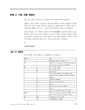
pTR v V@OY. p) mIn Y= }: p); V@OY. b; 3$*: pN =: x#& -/ |,aL Gb |nv p): Z?{8N mIn pe sB! VB ?H! mIn& Pb 15O mIn gL! v?8N ANW!VOb 'Q mIn! |Q 3mTOY. gkZ! p)! |[GB pg mInB ATN C[Gg ENTERN >aGn_ UOY. xi; JdQ DsLM& }+Q fl, DsLM *: 08N #VKOY. 9: ATH [ENTER] b; NO A. v? mInB p)L mIn pe! NDKOY. mInB kE R A.~n& G`OB PC GB W \G MLN e!NNM p)8N |[KOY. pg mInB k.Z GB R.ZN TBR v Vv8 k.ZM R.Z& %kO) TBR vB x@OY. mI n! AT mIn Y= qO!-
pTR v V@OY. p) mIn Y= }: p); V@OY. b; 3$*: pN =: x#& -/ |,aL Gb |nv p): Z?{8N mIn pe sB! VB ?H! mIn& Pb 15O mIn gL! v?8N ANW!VOb 'Q mIn! |Q 3mTOY. gkZ! p)! |[GB pg mInB ATN C[Gg ENTERN >aGn_ UOY. xi; JdQ DsLM& }+Q fl, DsLM *: 08N #VKOY. 9: ATH [ENTER] b; NO A. v? mInB p)L mIn pe! NDKOY. mInB kE R A.~n& G`OB PC GB W \G MLN e!NNM p)8N |[KOY. pg mInB k.Z GB R.ZN TBR v Vv8 k.ZM R.Z& %kO) TBR vB x@OY. mI n! AT mIn Y= qO!-


