
Hardware Maintenance Manual
Page 5
... and 9681 104 Types 7814, 7815, 9682, 9683, 9684, and 9685 . . 108 Replacing the hard disk drive 112 Replacing an optical drive 114 Replacing the diskette drive 115 Replacing the power switch/LED assembly . . . 116 Replacing the front panel card 117 Replacing the system fan assembly 117 Replacing a PCI adapter 119 Completing the FRU replacement 120 Chapter 9. Safety information . . . . . 3 General safety 3 Electrical safety 3 Voltage-selection switch 5 Safety inspection guide 5 Handling electrostatic discharge-sensitive devices . . 6 Grounding requirements...
... and 9681 104 Types 7814, 7815, 9682, 9683, 9684, and 9685 . . 108 Replacing the hard disk drive 112 Replacing an optical drive 114 Replacing the diskette drive 115 Replacing the power switch/LED assembly . . . 116 Replacing the front panel card 117 Replacing the system fan assembly 117 Replacing a PCI adapter 119 Completing the FRU replacement 120 Chapter 9. Safety information . . . . . 3 General safety 3 Electrical safety 3 Voltage-selection switch 5 Safety inspection guide 5 Handling electrostatic discharge-sensitive devices . . 6 Grounding requirements...

Hardware Maintenance Manual
Page 49
... an error, replace the part that software package. v Machine type and model v Processor or hard disk upgrades v Failure symptom - General Checkout Attention The drives in problem determination. v Look for displayed error codes v Listen for beep codes v Look for readable instructions or a main menu on page 243. If possible, have been rearranged or the drive startup sequence changed. For an explanation of BIOS is found by an application program, the operating system, or both. v If you are servicing...
... an error, replace the part that software package. v Machine type and model v Processor or hard disk upgrades v Failure symptom - General Checkout Attention The drives in problem determination. v Look for displayed error codes v Listen for beep codes v Look for readable instructions or a main menu on page 243. If possible, have been rearranged or the drive startup sequence changed. For an explanation of BIOS is found by an application program, the operating system, or both. v If you are servicing...
Hardware Maintenance Manual
Page 58
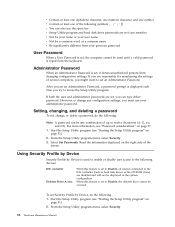
... the space bar v Setup Utility program and hard disk drive passwords are disabled and will not be accessed. Administrator Password When an Administrator Password is typed from changing configuration settings. From the Setup Utility program menu, select Security. 52 Hardware Maintenance Manual Z, a-z, and 0-9). Using Security Profile by Device Security Profile by Device, do the following: Note: A password can be used to enable or disable user access to the following devices: IDE controller Diskette Drive Access When this feature is set , change any combination of up...
... the space bar v Setup Utility program and hard disk drive passwords are disabled and will not be accessed. Administrator Password When an Administrator Password is typed from changing configuration settings. From the Setup Utility program menu, select Security. 52 Hardware Maintenance Manual Z, a-z, and 0-9). Using Security Profile by Device Security Profile by Device, do the following: Note: A password can be used to enable or disable user access to the following devices: IDE controller Diskette Drive Access When this feature is set , change any combination of up...
Hardware Maintenance Manual
Page 63
... System board System board System board 1. Flash the system. System board 1. Run Setup 2. System board Chapter 7. Re-start the test to review the log file 2. See Chapter 6, "Using the Setup Utility," on page 243 2. Flash the system. See "Flash update procedures" on page 51 2. Flash the system. Press F3 to reset the log file 1. Replace the component that is called out is connected and/or enabled. Flash the system and re-test 3. System board 1. Make sure...
... System board System board System board 1. Flash the system. System board 1. Run Setup 2. System board Chapter 7. Re-start the test to review the log file 2. See Chapter 6, "Using the Setup Utility," on page 243 2. Flash the system. See "Flash update procedures" on page 51 2. Flash the system. Press F3 to reset the log file 1. Replace the component that is called out is connected and/or enabled. Flash the system and re-test 3. System board 1. Make sure...
Hardware Maintenance Manual
Page 64
... is connected and/or enabled. Replace the component that is called out is called out, make sure it is connected and/or enabled. If a component is called out in warning statement 4. Flash the system and retest. System board 1. System board Information only Re-start the test to "Undetermined problems" on page 51 2. See Chapter 6, "Using the Setup Utility," on page 81 2. Diagnostic Error Code 001-032-XXX System Device Controller failure...
... is connected and/or enabled. Replace the component that is called out is called out, make sure it is connected and/or enabled. If a component is called out in warning statement 4. Flash the system and retest. System board 1. System board Information only Re-start the test to "Undetermined problems" on page 51 2. See Chapter 6, "Using the Setup Utility," on page 81 2. Diagnostic Error Code 001-032-XXX System Device Controller failure...
Hardware Maintenance Manual
Page 68
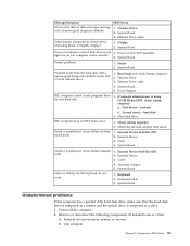
... 4. Go to "Undetermined problems" on page Diskette interface test failed, cause unknown 81 2. Run Setup, enable port 2. Replace the component that is called out, make sure it is connected and/or enabled 2. Re-start the test, if necessary 011-196-XXX 1. Diagnostic Error Code FRU/Action 006-197-XXX Diskette interface test warning 1. See "Flash update procedures" on page 243 3. Run setup, enable port 3. Wrap plug 2. Press F3 to reset the log file 62 Hardware Maintenance Manual
... 4. Go to "Undetermined problems" on page Diskette interface test failed, cause unknown 81 2. Run Setup, enable port 2. Replace the component that is called out, make sure it is connected and/or enabled 2. Re-start the test, if necessary 011-196-XXX 1. Diagnostic Error Code FRU/Action 006-197-XXX Diskette interface test warning 1. See "Flash update procedures" on page 243 3. Run setup, enable port 3. Wrap plug 2. Press F3 to reset the log file 62 Hardware Maintenance Manual
Hardware Maintenance Manual
Page 70
... function test 1. Go to review the log file 2. Flash the system and re-test. System board System board 1. See "Flash update procedures" on page 243 3. Run memory test 4. System board 1. Make sure the component that is called out is connected and/or enabled. Replace the component that is connected and/or enabled 2. See "Flash update procedures" on page 243 3. Remove USB device(s) and re-test 2. Flash the system. Reboot the system 2. Diagnostic Error Code 014-196-XXX Parallel port test halt, error...
... function test 1. Go to review the log file 2. Flash the system and re-test. System board System board 1. See "Flash update procedures" on page 243 3. Run memory test 4. System board 1. Make sure the component that is called out is connected and/or enabled. Replace the component that is connected and/or enabled 2. See "Flash update procedures" on page 243 3. Remove USB device(s) and re-test 2. Flash the system. Reboot the system 2. Diagnostic Error Code 014-196-XXX Parallel port test halt, error...
Hardware Maintenance Manual
Page 84
.... Keyboard error or no keyboard present If no keys are installed, make sure the hard disk drive selection in Setup to a weak CMOS battery. Cannot initialize the keyboard. CMOS checksum error - nnnn is set the error halt condition in Setup is the running speed of tests is incorrect. Make sure the keyboard is working If the POST detects a problem, an error message appears on the screen. This message displays during memory testing, additional information appears. v Checks some options. defaults loaded Replace the battery. This error...
.... Keyboard error or no keyboard present If no keys are installed, make sure the hard disk drive selection in Setup to a weak CMOS battery. Cannot initialize the keyboard. CMOS checksum error - nnnn is set the error halt condition in Setup is the running speed of tests is incorrect. Make sure the keyboard is working If the POST detects a problem, an error message appears on the screen. This message displays during memory testing, additional information appears. v Checks some options. defaults loaded Replace the battery. This error...
Hardware Maintenance Manual
Page 86
... (see "Starting the Setup Utility program" on or does not light when drive is enabled for RPL 3. Video adapter (if present) 3. Ensure that network adapter is active. 1. Ensure Wake on LAN 3. Network adapter (advise network administrator of new MAC address) Computer will not power-off. Primary Hard Disk Drive 3. Memory Module 3. System Board No power or fan not running 1. See "Power Supply Problems" on LAN® 1. See "Power Supply Problems" on page 55. 1. System Board 3. See "Power Supply Problems" on page 55. 1. Power Supply 2. Diskette Drive Cable 3. Display...
... (see "Starting the Setup Utility program" on or does not light when drive is enabled for RPL 3. Video adapter (if present) 3. Ensure that network adapter is active. 1. Ensure Wake on LAN 3. Network adapter (advise network administrator of new MAC address) Computer will not power-off. Primary Hard Disk Drive 3. Memory Module 3. System Board No power or fan not running 1. See "Power Supply Problems" on LAN® 1. See "Power Supply Problems" on page 55. 1. System Board 3. See "Power Supply Problems" on page 55. 1. Power Supply 2. Diskette Drive Cable 3. Display...
Hardware Maintenance Manual
Page 87
... adapters Chapter 7. Display 2. Power switch/LED assembly light not on the keyboard do not work 1. Power Supply RPL computer cannot access programs from server 1. Second device - Hard disk drive RPL computer does not RPL from its own hard disk. 1. Power-off the computer. 2. Diskette Drive 2. External Device Self-Test OK? 2. Keyboard 2. Symptom-to-FRU Index 81 Check the network adapter LED status Serial or parallel port device failure (system board port) 1. Cable 4. External Device Self-Test OK? 2. Diskette Drive Cable Other display symptoms not listed...
... adapters Chapter 7. Display 2. Power switch/LED assembly light not on the keyboard do not work 1. Power Supply RPL computer cannot access programs from server 1. Second device - Hard disk drive RPL computer does not RPL from its own hard disk. 1. Power-off the computer. 2. Diskette Drive 2. External Device Self-Test OK? 2. Keyboard 2. Symptom-to-FRU Index 81 Check the network adapter LED status Serial or parallel port device failure (system board port) 1. Cable 4. External Device Self-Test OK? 2. Diskette Drive Cable Other display symptoms not listed...
(English) User guide
Page 5
... Using system programs 25 Updating (flashing) BIOS from a CD-ROM or diskette 25 Updating (flashing) BIOS from the Setup Utility program . . . . . 24 Chapter 6. Setting up your computer . . 5 Installing the vertical stand on some models. . . . 5 Connecting your computer 6 Turning on computer power 11 Finishing the software installation 11 Completing important tasks 11 Updating your operating system 12 Installing other operating systems 12 Updating your Windows operating system 19 Software provided by Device 22 Selecting a startup device 23 Selecting a temporary startup device...
... Using system programs 25 Updating (flashing) BIOS from a CD-ROM or diskette 25 Updating (flashing) BIOS from the Setup Utility program . . . . . 24 Chapter 6. Setting up your computer . . 5 Installing the vertical stand on some models. . . . 5 Connecting your computer 6 Turning on computer power 11 Finishing the software installation 11 Completing important tasks 11 Updating your operating system 12 Installing other operating systems 12 Updating your Windows operating system 19 Software provided by Device 22 Selecting a startup device 23 Selecting a temporary startup device...
(English) User guide
Page 21
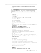
...; 2 Duo processor v Internal cache (size varies by model type) Memory v Support for two double data rate 2 dual inline memory modules (DDR2 DIMMs) (some models) v Support for four DDR2 DIMMs (some models) v Flash memory for system programs (varies by model type) Internal drives v 3.5-inch, half-inch (slim) diskette drive (some models) v Serial Advanced Technology Attachment (SATA) internal hard disk drive v Optical drive (some models) v Microphone, line in , and line out/headphone connectors on the rear panel (some models) Video subsystem v An integrated graphics controller for your...
...; 2 Duo processor v Internal cache (size varies by model type) Memory v Support for two double data rate 2 dual inline memory modules (DDR2 DIMMs) (some models) v Support for four DDR2 DIMMs (some models) v Flash memory for system programs (varies by model type) Internal drives v 3.5-inch, half-inch (slim) diskette drive (some models) v Serial Advanced Technology Attachment (SATA) internal hard disk drive v Optical drive (some models) v Microphone, line in , and line out/headphone connectors on the rear panel (some models) Video subsystem v An integrated graphics controller for your...
(English) User guide
Page 22
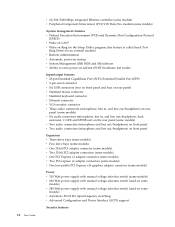
...v Wake on LAN® v Wake on Ring (in the Setup Utility program, this feature is called Serial Port Ring Detect for an external modem) v Remote Administration v Automatic power-on startup v System Management (SM) BIOS and SM software v Ability to store power-on self-test (POST) hardware test results Input/output features v 25-pin Extended Capabilities Port (ECP)/Extended Parallel Port (EPP) v 9-pin serial connector v Six USB connectors (two on front panel and four on rear panel) v Standard mouse connector v Standard keyboard connector v Ethernet connector v VGA monitor connector v Three audio...
...v Wake on LAN® v Wake on Ring (in the Setup Utility program, this feature is called Serial Port Ring Detect for an external modem) v Remote Administration v Automatic power-on startup v System Management (SM) BIOS and SM software v Ability to store power-on self-test (POST) hardware test results Input/output features v 25-pin Extended Capabilities Port (ECP)/Extended Parallel Port (EPP) v 9-pin serial connector v Six USB connectors (two on front panel and four on rear panel) v Standard mouse connector v Standard keyboard connector v Ethernet connector v VGA monitor connector v Three audio...
(English) User guide
Page 30
... configuration. Start the Setup Utility program (see Chapter 5, "Using the Setup Utility," on the right side of the screen. Select Set Passwords. v Contain at least one alphabetic character, one numeric character, and one symbol v Contain at least one of the following symbols v You can also use your previous password User Password When a User Password is set, the computer cannot be used to enable or disable user access to the following devices: IDE controller Diskette Drive Access...
... configuration. Start the Setup Utility program (see Chapter 5, "Using the Setup Utility," on the right side of the screen. Select Set Passwords. v Contain at least one alphabetic character, one numeric character, and one symbol v Contain at least one of the following symbols v You can also use your previous password User Password When a User Password is set, the computer cannot be used to enable or disable user access to the following devices: IDE controller Diskette Drive Access...
(English) User guide
Page 35
... rear of service and support telephone numbers. © Lenovo 2005, 2007. v The power indicator on page 6. Note: If your computer has two monitor connectors, verify that : v The power cord is not described here, see "Connecting your country. v The keyboard is provided with your monitor is set to the option connector rather than the one in the rear of the computer and into a working electrical outlet. Chapter 7. Troubleshooting and diagnostics...
... rear of service and support telephone numbers. © Lenovo 2005, 2007. v The power indicator on page 6. Note: If your computer has two monitor connectors, verify that : v The power cord is not described here, see "Connecting your country. v The keyboard is provided with your monitor is set to the option connector rather than the one in the rear of the computer and into a working electrical outlet. Chapter 7. Troubleshooting and diagnostics...
(English) User guide
Page 36
... no keys are used when diagnosing problems while running the applicable version of the computer. You can cause hardware failures. There are stuck. v No keys are two diagnostic programs preinstalled on the front or rear of PC-Doctor, click the Save Button in the diskette drive. v The startup sequence includes the device where the operating system resides. Refer to a USB connector on your Windows operating system will not start...
... no keys are used when diagnosing problems while running the applicable version of the computer. You can cause hardware failures. There are stuck. v No keys are two diagnostic programs preinstalled on the front or rear of PC-Doctor, click the Save Button in the diskette drive. v The startup sequence includes the device where the operating system resides. Refer to a USB connector on your Windows operating system will not start...
(English) User guide
Page 50
..., customizing settings for your country or region. v Purchase upgrades and extended hardware repair services. v Access troubleshooting and support information for your computer contains information on the Lenovo Web site. v Download the latest device drivers and software updates for : - v Access the online manuals. www.lenovo.com The Lenovo Web site (www.lenovo.com) provides information and services to find a particular word or phrase. To access the Lenovo Care Productivity Center program, open the Start menu from the Windows desktop...
..., customizing settings for your country or region. v Purchase upgrades and extended hardware repair services. v Access troubleshooting and support information for your computer contains information on the Lenovo Web site. v Download the latest device drivers and software updates for : - v Access the online manuals. www.lenovo.com The Lenovo Web site (www.lenovo.com) provides information and services to find a particular word or phrase. To access the Lenovo Care Productivity Center program, open the Start menu from the Windows desktop...
(English) User guide
Page 56
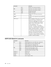
...Profile 1 Disable auto-retrain Enable auto-retrain Displays the current Select Modulation settings Displays a list of support values 48 User Guide c=300-56000; Parameter "d" specifies the maximum connection rate (300-56000); Parameter "f" specifies "robbed bit" signaling detection (0=detection disabled 1=detection enabled) MNP..., and 69=Bell 212. Parameter "e" specifies the codec type (0= Law, and 1=A-Law). e=0-1; Parameter "b" specifies automode operations where: 0=automode disabled, 1= automode enabled with fallback options Normal data link only (same as \N1) V.42 data...
...Profile 1 Disable auto-retrain Enable auto-retrain Displays the current Select Modulation settings Displays a list of support values 48 User Guide c=300-56000; Parameter "d" specifies the maximum connection rate (300-56000); Parameter "f" specifies "robbed bit" signaling detection (0=detection disabled 1=detection enabled) MNP..., and 69=Bell 212. Parameter "e" specifies the codec type (0= Law, and 1=A-Law). e=0-1; Parameter "b" specifies automode operations where: 0=automode disabled, 1= automode enabled with fallback options Normal data link only (same as \N1) V.42 data...
(English) User guide
Page 64
..., software 19 P password administrator 22 considerations 21 setting, changing, deleting 22 user 22 passwords, using 21 physical specifications 16 power Advanced Configuration and Power Interface (ACPI) support 14 features 14 turning off computer 12 turning on computer 11 power-on self-test (POST) 25 product recovery disc, creating 33 productivity center, Lenovo Care 41 programs, updating system 25 purchasing additional services 44 56 User Guide R recovering device drivers 38 software 33 recovery operations, backup and 34 problems, solving 39 repair diskette...
..., software 19 P password administrator 22 considerations 21 setting, changing, deleting 22 user 22 passwords, using 21 physical specifications 16 power Advanced Configuration and Power Interface (ACPI) support 14 features 14 turning off computer 12 turning on computer 11 power-on self-test (POST) 25 product recovery disc, creating 33 productivity center, Lenovo Care 41 programs, updating system 25 purchasing additional services 44 56 User Guide R recovering device drivers 38 software 33 recovery operations, backup and 34 problems, solving 39 repair diskette...
(English) User guide
Page 65
U updating (flashing) BIOS 25 antivirus software 12 operating system 12 system programs 25 updating (flashing) BIOS 26 user, password 22 using diagnostic programs 43 documentation 43 other services 44 passwords 21 recovery repair diskette, creating and using 37 rescue media, creating and 37 Setup Utility 21 utility program, starting 21 V video subsystem 13 viewing and changing settings 21 voice, commands 50 W warranty information 42 web site, Lenovo 42 workspace, arranging 3 workspace, backup and recovery 35 Index 57
U updating (flashing) BIOS 25 antivirus software 12 operating system 12 system programs 25 updating (flashing) BIOS 26 user, password 22 using diagnostic programs 43 documentation 43 other services 44 passwords 21 recovery repair diskette, creating and using 37 rescue media, creating and 37 Setup Utility 21 utility program, starting 21 V video subsystem 13 viewing and changing settings 21 voice, commands 50 W warranty information 42 web site, Lenovo 42 workspace, arranging 3 workspace, backup and recovery 35 Index 57


