Hardware Maintenance Manual for K220
Page 3
... and power interface (ACPI) BIOS 58 Power Management features 58 Chapter 12. Contents Replacing the power supply 43 Replacing the heat sink assembly 44 Replacing a memory module 45 Replacing an adapter 46 Note: Replacement of some models equipped with graphic adapter bracket is different...48 Replacing the hard disk drive 49...
... and power interface (ACPI) BIOS 58 Power Management features 58 Chapter 12. Contents Replacing the power supply 43 Replacing the heat sink assembly 44 Replacing a memory module 45 Replacing an adapter 46 Note: Replacement of some models equipped with graphic adapter bracket is different...48 Replacing the hard disk drive 49...
Hardware Maintenance Manual for K220
Page 5
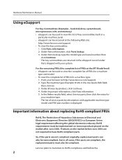
...placed on the market before the 2 Important information about replacing RoHS compliant FRUs RoHS, The Restriction of FRUs at the following Web site: http://www.lenovo.com/support •• To view the key commodities: 1. Type the machine type (Example: 8129) in a particular machine serial. ••...; To view the complete list of key commodities built in the Use Quick Path field; hard disk drive, system board, microprocessor, LCD, and memory) •• eSupport can be used to view the complete list of FRUs for a machine type: 1. In the Refine results field, select Service...
...placed on the market before the 2 Important information about replacing RoHS compliant FRUs RoHS, The Restriction of FRUs at the following Web site: http://www.lenovo.com/support •• To view the key commodities: 1. Type the machine type (Example: 8129) in a particular machine serial. ••...; To view the complete list of key commodities built in the Use Quick Path field; hard disk drive, system board, microprocessor, LCD, and memory) •• eSupport can be used to view the complete list of FRUs for a machine type: 1. In the Refine results field, select Service...

Hardware Maintenance Manual for K220
Page 16
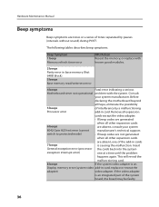
...For an explanation of these messages, refer to help determine the cause of BIOS is found by POST. • To enable beep, memory count, and checkpoint code display when a successful POST occurs, do the following procedure to the information supplied with that the latest level ...are detected by an application program, the operating system, or both. General Checkout Attention The drives in quiet mode (no beep, no memory count and checkpoint code display) when no errors are servicing might cause false errors and unnecessary replacement of the system board. Select Start Options...
...For an explanation of these messages, refer to help determine the cause of BIOS is found by POST. • To enable beep, memory count, and checkpoint code display when a successful POST occurs, do the following procedure to the information supplied with that the latest level ...are detected by an application program, the operating system, or both. General Checkout Attention The drives in quiet mode (no beep, no memory count and checkpoint code display) when no errors are servicing might cause false errors and unnecessary replacement of the system board. Select Start Options...
Hardware Maintenance Manual for K220
Page 39
... replace with the system. This will reveal the malfunctioning card. 8 beeps If the system video adapter is an Display memory error (system video add-in base memory (first 64KB block) 3 beeps Base memory read/write test error 4 beeps Fatal error indicating a serious Motherboard timer not operational problem with known good modules. 2 beeps Parity...
... replace with the system. This will reveal the malfunctioning card. 8 beeps If the system video adapter is an Display memory error (system video add-in base memory (first 64KB block) 3 beeps Base memory read/write test error 4 beeps Fatal error indicating a serious Motherboard timer not operational problem with known good modules. 2 beeps Parity...
Hardware Maintenance Manual for K220
Page 40
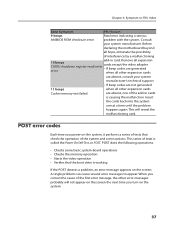
... error codes Each time you turn on the system, it performs a series of the first error message, the other expansion cards Cache memory test failed are absent, consult your system manufacturer. Chapter 6. This series of interference by a malfunctioning add-in cards is causing the... you power-on the system. 37 POST does the following operations. • Checks some basic system-board operations • Checks the memory operation • Starts the video operation • Verifies that check the operation of the add-in card. Consult your system manufacturer's technical...
... error codes Each time you turn on the system, it performs a series of the first error message, the other expansion cards Cache memory test failed are absent, consult your system manufacturer. Chapter 6. This series of interference by a malfunctioning add-in cards is causing the... you power-on the system. 37 POST does the following operations. • Checks some basic system-board operations • Checks the memory operation • Starts the video operation • Verifies that check the operation of the add-in card. Consult your system manufacturer's technical...
Hardware Maintenance Manual for K220
Page 42
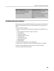
... system board. 39 Make sure the boot drive is jumpered as a slave. 1. Make sure you find a suitable boot device. Extended video memory e. Undetermined problems If this computer has a parallel ATA hard disk drive, make sure that the hard disk drive is jumpered as a master ...and the optical drive is properly connected to re-test the system. 4. a. Memory modules d. External Cache RAM g. Hard disk drive h. Diskette drive 3. Chapter 6. External devices (modem, printer, or mouse) b. External Cache f. Power-...
... system board. 39 Make sure the boot drive is jumpered as a slave. 1. Make sure you find a suitable boot device. Extended video memory e. Undetermined problems If this computer has a parallel ATA hard disk drive, make sure that the hard disk drive is jumpered as a master ...and the optical drive is properly connected to re-test the system. 4. a. Memory modules d. External Cache RAM g. Hard disk drive h. Diskette drive 3. Chapter 6. External devices (modem, printer, or mouse) b. External Cache f. Power-...
Hardware Maintenance Manual for K220
Page 48
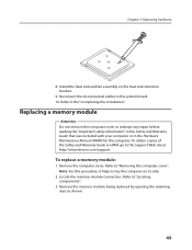
...2. Refer to lay the computer on the heat sink retention bracket. 9. Note: For this procedure, it helps to "Removing the computer cover". Chapter 7. Replacing a memory module Attention Do not remove the computer cover or attempt any repair before reading the "Important safety information" in the Safety and Warranty Guide that... included with your computer or in the Hardware Maintenance Manual (HMM) for the computer. Refer to the Support Web site at http://www.lenovo.com/support. To obtain copies of the Safety and Warranty Guide or HMM, go to "Locating components". 3. Locate the...
...2. Refer to lay the computer on the heat sink retention bracket. 9. Note: For this procedure, it helps to "Removing the computer cover". Chapter 7. Replacing a memory module Attention Do not remove the computer cover or attempt any repair before reading the "Important safety information" in the Safety and Warranty Guide that... included with your computer or in the Hardware Maintenance Manual (HMM) for the computer. Refer to the Support Web site at http://www.lenovo.com/support. To obtain copies of the Safety and Warranty Guide or HMM, go to "Locating components". 3. Locate the...
Hardware Maintenance Manual for K220
Page 49
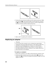
...it straight out of the Safety and Warranty Guide or HMM, go to the Support Web site at http://www.lenovo.com/support. Make sure the notch on the memory aligns correctly with your computer or in the Hardware Maintenance Manual (HMM) for the computer. Remove the computer cover.... and Warranty Guide that was included with the connector key on the system board. Position the new memory module over the memory connector. To obtain copies of the adapter connector. 46 Push the memory module straight down into the connector until the retaining clips close. 5. To replace an adapter: 1....
...it straight out of the Safety and Warranty Guide or HMM, go to the Support Web site at http://www.lenovo.com/support. Make sure the notch on the memory aligns correctly with your computer or in the Hardware Maintenance Manual (HMM) for the computer. Remove the computer cover.... and Warranty Guide that was included with the connector key on the system board. Position the new memory module over the memory connector. To obtain copies of the adapter connector. 46 Push the memory module straight down into the connector until the retaining clips close. 5. To replace an adapter: 1....
IdeaCentre K220 Hardware Replacement Guide
Page 3
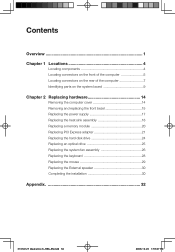
... 14 Removing the computer cover 14 Removing and replacing the front bezel 15 Replacing the power supply 17 Replacing the heat sink assembly 18 Replacing a memory module 20 Replacing PCI Express adapter 21 Replacing the hard disk drive 24 Replacing an optical drive 25 Replacing the system fan assembly 26 Replacing... the keyboard 28 Replacing the mouse 29 Replacing the External speaker 30 Completing the installation 30 Appendix 32 31036127 IdeaCentre K_HRG_EN.indd 36 2008.10.20 1:59:47 PM
... 14 Removing the computer cover 14 Removing and replacing the front bezel 15 Replacing the power supply 17 Replacing the heat sink assembly 18 Replacing a memory module 20 Replacing PCI Express adapter 21 Replacing the hard disk drive 24 Replacing an optical drive 25 Replacing the system fan assembly 26 Replacing... the keyboard 28 Replacing the mouse 29 Replacing the External speaker 30 Completing the installation 30 Appendix 32 31036127 IdeaCentre K_HRG_EN.indd 36 2008.10.20 1:59:47 PM
IdeaCentre K220 Hardware Replacement Guide
Page 4
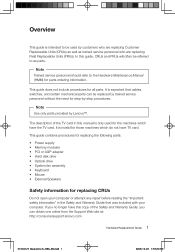
... that cables, switches, and certain mechanical parts can obtain one online from the Support Web site at: http://consumersupport.lenovo.com Hardware Replacement Guide 1 31036127 IdeaCentre K_HRG_EN.indd 1 2008.10.20 1:59:20 PM It is only used by customers who are replacing Customer Replaceable... is invalid for those machines which have the TV card. Note Use only parts provided by Lenovo™. This guide contains procedures for replacing the following parts: • Power supply • Memory modules • PCI or AGP adapter • Hard disk drive • Optical drive ...
... that cables, switches, and certain mechanical parts can obtain one online from the Support Web site at: http://consumersupport.lenovo.com Hardware Replacement Guide 1 31036127 IdeaCentre K_HRG_EN.indd 1 2008.10.20 1:59:20 PM It is only used by customers who are replacing Customer Replaceable... is invalid for those machines which have the TV card. Note Use only parts provided by Lenovo™. This guide contains procedures for replacing the following parts: • Power supply • Memory modules • PCI or AGP adapter • Hard disk drive • Optical drive ...
IdeaCentre K220 Hardware Replacement Guide
Page 5
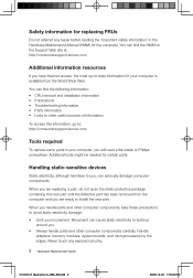
...certain parts. Handle adapters, memory modules, system boards, and microprocessors by the edges. Handling static-sensitive devices Static electricity, although harmless to install the new part. Movement can find the HMM on the Support Web site at: http://consumersupport.lenovo.com Additional information resources If ... Wide Web. Safety information for replacing FRUs Do not attempt any exposed circuitry. 2 Hardware Replacement Guide 31036127 IdeaCentre K_HRG_EN.indd 2 2008.10.20 1:59:20 PM When you are ready to you handle parts and other computer components carefully.
...certain parts. Handle adapters, memory modules, system boards, and microprocessors by the edges. Handling static-sensitive devices Static electricity, although harmless to install the new part. Movement can find the HMM on the Support Web site at: http://consumersupport.lenovo.com Additional information resources If ... Wide Web. Safety information for replacing FRUs Do not attempt any exposed circuitry. 2 Hardware Replacement Guide 31036127 IdeaCentre K_HRG_EN.indd 2 2008.10.20 1:59:20 PM When you are ready to you handle parts and other computer components carefully.
IdeaCentre K220 Hardware Replacement Guide
Page 8
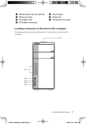
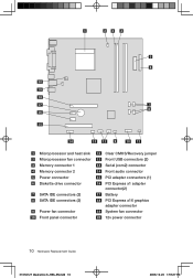
Microprocessor fan and heat sink Memory modules PCI adapter card PCI adapter connectors Power supply System fan PCI Express connectors Locating connectors on the front of the computer The following illustration shows the location of connectors on the front of the computer. F-1 xD CF/I/II/MD MS/Pro/Duo/ProDuo SD/Mini/HC/MiniHC MMC/RS/Plus/Mob D-1 D-2 D-3 D-4 D-2 31036127 IdeaCentre K_HRG_EN.indd 5 Hardware Replacement Guide 5 2008.10.20 1:59:21 PM
Microprocessor fan and heat sink Memory modules PCI adapter card PCI adapter connectors Power supply System fan PCI Express connectors Locating connectors on the front of the computer The following illustration shows the location of connectors on the front of the computer. F-1 xD CF/I/II/MD MS/Pro/Duo/ProDuo SD/Mini/HC/MiniHC MMC/RS/Plus/Mob D-1 D-2 D-3 D-4 D-2 31036127 IdeaCentre K_HRG_EN.indd 5 Hardware Replacement Guide 5 2008.10.20 1:59:21 PM
IdeaCentre K220 Hardware Replacement Guide
Page 13
Microprocessor and heat sink Microprocessor fan connector Memory connector 1 Memory connector 2 Power connector Diskette drive connector SATA IDE connectors (2) SATA IDE connectors (2) Power fan connector Front panel connector Clear CMOS/Recovery jumper Front USB connectors (2) Serial (com2) connector Front audio connector PCI adapter connectors (1) PCI Express x1 adapter connector(2) Battery PCI Express x16 graphics adapter connector System fan connector 12v power connector 10 Hardware Replacement Guide 31036127 IdeaCentre K_HRG_EN.indd 10 2008.10.20 1:59:27 PM
Microprocessor and heat sink Microprocessor fan connector Memory connector 1 Memory connector 2 Power connector Diskette drive connector SATA IDE connectors (2) SATA IDE connectors (2) Power fan connector Front panel connector Clear CMOS/Recovery jumper Front USB connectors (2) Serial (com2) connector Front audio connector PCI adapter connectors (1) PCI Express x1 adapter connector(2) Battery PCI Express x16 graphics adapter connector System fan connector 12v power connector 10 Hardware Replacement Guide 31036127 IdeaCentre K_HRG_EN.indd 10 2008.10.20 1:59:27 PM
IdeaCentre K220 Hardware Replacement Guide
Page 17
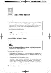
Refer to the Support Web site at: http://consumersupport.lenovo.com Note Use only parts provided by Lenovo. Chapter Replacing hardware Attention Do not remove the computer cover or attempt any media (diskettes, CDs, or memory cards) from electrical outlets. 3. To obtain copies of the Safety and ...Warranty Guide or HMM, go to "Locating connectors on the front of the computer" and "Locating connectors on the rear of the computer". 14 Hardware Replacement Guide 31036127 IdeaCentre K_HRG_EN.indd 14...
Refer to the Support Web site at: http://consumersupport.lenovo.com Note Use only parts provided by Lenovo. Chapter Replacing hardware Attention Do not remove the computer cover or attempt any media (diskettes, CDs, or memory cards) from electrical outlets. 3. To obtain copies of the Safety and ...Warranty Guide or HMM, go to "Locating connectors on the front of the computer" and "Locating connectors on the rear of the computer". 14 Hardware Replacement Guide 31036127 IdeaCentre K_HRG_EN.indd 14...
IdeaCentre K220 Hardware Replacement Guide
Page 23
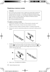
...IdeaCentre K_HRG_EN.indd 20 2008.10.20 1:59:36 PM Remove the memory module being replaced by opening the retaining clips as shown. 4. Refer to "Removing the computer cover". Locate the memory module connectors. Remove the computer cover. Refer to the Support Web site at: http://consumersupport.lenovo....com To replace a memory module: 1. Note: For this procedure, it helps to lay the ...
...IdeaCentre K_HRG_EN.indd 20 2008.10.20 1:59:36 PM Remove the memory module being replaced by opening the retaining clips as shown. 4. Refer to "Removing the computer cover". Locate the memory module connectors. Remove the computer cover. Refer to the Support Web site at: http://consumersupport.lenovo....com To replace a memory module: 1. Note: For this procedure, it helps to lay the ...

IdeaCentre K220 Hardware Replacement Guide
Page 31
... keyboard. Refer to "Locating connectors on the rear of the computer" and "Locating connectors on the tips of the computer". 28 Hardware Replacement Guide 31036127 IdeaCentre K_HRG_EN.indd 28 2008.10.20 1:59:43 PM Pull on the front of the rubber mounts until the fan assembly is in place. 7. Connect... the system fan assembly cable to the "Completing the installation". Replacing the keyboard To replace the keyboard: 1. Remove any media (diskettes, CDs, or memory cards) from electrical outlets. 3. 6.
... keyboard. Refer to "Locating connectors on the rear of the computer" and "Locating connectors on the tips of the computer". 28 Hardware Replacement Guide 31036127 IdeaCentre K_HRG_EN.indd 28 2008.10.20 1:59:43 PM Pull on the front of the rubber mounts until the fan assembly is in place. 7. Connect... the system fan assembly cable to the "Completing the installation". Replacing the keyboard To replace the keyboard: 1. Remove any media (diskettes, CDs, or memory cards) from electrical outlets. 3. 6.
IdeaCentre K220 Hardware Replacement Guide
Page 32
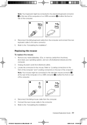
Disconnect the failing keyboard cable from the computer. 5. Remove any media (diskettes, CDs, or memory cards) from the drives, shut down your operating system, and turn off all power cords from electrical outlets. 3. Note: Your mouse might be connected to ... installation". Refer to "Locating connectors on the front of the computer" and "Locating connectors on the rear of the computer". Hardware Replacement Guide 29 31036127 IdeaCentre K_HRG_EN.indd 29 2008.10.20 1:59:45 PM Note: Your keyboard might be connected to the standard keyboard connector at the rear of the...
Disconnect the failing keyboard cable from the computer. 5. Remove any media (diskettes, CDs, or memory cards) from the drives, shut down your operating system, and turn off all power cords from electrical outlets. 3. Note: Your mouse might be connected to ... installation". Refer to "Locating connectors on the front of the computer" and "Locating connectors on the rear of the computer". Hardware Replacement Guide 29 31036127 IdeaCentre K_HRG_EN.indd 29 2008.10.20 1:59:45 PM Note: Your keyboard might be connected to the standard keyboard connector at the rear of the...
IdeaCentre K220 Hardware Replacement Guide
Page 33
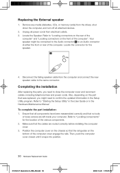
... confirm the updated information in the Hardware Maintenance Manual. Also, depending on the bottom of the computer. Remove any media (diskettes, CDs, or memory cards) from electrical outlets. 3. Replacing the External speaker 1. Completing the installation After replacing the parts, you might be connected to the Audio connector to "Locating... and reconnect cables, including telephone lines and power cords. Then, push the computer cover closed until it snaps into position. 30 Hardware Replacement Guide 31036127 IdeaCentre K_HRG_EN.indd 30 2008.10.20 1:59:45 PM
... confirm the updated information in the Hardware Maintenance Manual. Also, depending on the bottom of the computer. Remove any media (diskettes, CDs, or memory cards) from electrical outlets. 3. Replacing the External speaker 1. Completing the installation After replacing the parts, you might be connected to the Audio connector to "Locating... and reconnect cables, including telephone lines and power cords. Then, push the computer cover closed until it snaps into position. 30 Hardware Replacement Guide 31036127 IdeaCentre K_HRG_EN.indd 30 2008.10.20 1:59:45 PM

IdeaCentre K220 User Guide
Page 8
... audio input to these. The following illustrations show connections located at the rear of all I /CF II/ MD. D-1 Memory card reader Connector: Able to read/write data from Memory Stick /Memory Stick Pro/ Memory Stick Duo /Memory Stick Pro Duo xD SD/Mini SD/SD High Capacity /Mini SD High Capacity/ MMC/ RS-MMC/MMC...
... audio input to these. The following illustrations show connections located at the rear of all I /CF II/ MD. D-1 Memory card reader Connector: Able to read/write data from Memory Stick /Memory Stick Pro/ Memory Stick Duo /Memory Stick Pro Duo xD SD/Mini SD/SD High Capacity /Mini SD High Capacity/ MMC/ RS-MMC/MMC...


