Safety and Warranty guide
Page 9
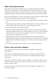
...: • Limit your body. • When possible, remove the static-sensitive part from touching components. • When you . • Always handle components carefully. Handle adapters, memory modules, and other countries, the suitable types shall be walked on the computer for at least two seconds. When you unpack an option or CRU...
...: • Limit your body. • When possible, remove the static-sensitive part from touching components. • When you . • Always handle components carefully. Handle adapters, memory modules, and other countries, the suitable types shall be walked on the computer for at least two seconds. When you unpack an option or CRU...
Lenovo C3/C4/C5 Series User Guide
Page 8
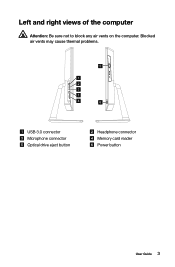
Left and right views of the computer Attention: Be sure not to block any air vents on the computer. Blocked air vents may cause thermal problems. 5 1 2 3 1 4 6 USB 3.0 connector Microphone connector Optical drive eject button Headphone connector Memory card reader Power button User Guide 3
Left and right views of the computer Attention: Be sure not to block any air vents on the computer. Blocked air vents may cause thermal problems. 5 1 2 3 1 4 6 USB 3.0 connector Microphone connector Optical drive eject button Headphone connector Memory card reader Power button User Guide 3
Lenovo C3/C4/C5 Series User Guide
Page 42
Hardware Replacement Guide This chapter contains the following topics: Ø Removing the stand base Ø Removing the foot cover Ø Replacing a memory module Ø Replacing the hard disk drive Ø Replacing the optical drive Ø Replacing the adapter Ø Replacing the keyboard and mouse User Guide 37
Hardware Replacement Guide This chapter contains the following topics: Ø Removing the stand base Ø Removing the foot cover Ø Replacing a memory module Ø Replacing the hard disk drive Ø Replacing the optical drive Ø Replacing the adapter Ø Replacing the keyboard and mouse User Guide 37
Lenovo C3/C4/C5 Series User Guide
Page 43
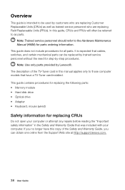
...of the Safety and Warranty Guide, you no longer have a TV-Tuner card installed. This guide contains procedures for replacing the following parts: • Memory module • Hard disk drive • Optical drive • Adapter • Keyboard, mouse (wired) Safety information for replacing CRUs Do not open... and Warranty Guide that cables, switches, and certain mechanical parts can obtain one online from the Support Web site at http://support.lenovo.com. 38 User Guide Overview This guide is expected that was included with your computer or attempt any repairs before reading the "...
...of the Safety and Warranty Guide, you no longer have a TV-Tuner card installed. This guide contains procedures for replacing the following parts: • Memory module • Hard disk drive • Optical drive • Adapter • Keyboard, mouse (wired) Safety information for replacing CRUs Do not open... and Warranty Guide that cables, switches, and certain mechanical parts can obtain one online from the Support Web site at http://support.lenovo.com. 38 User Guide Overview This guide is expected that was included with your computer or attempt any repairs before reading the "...

Lenovo C3/C4/C5 Series User Guide
Page 45
Handle adapters, memory modules, system boards, and microprocessors by the edges. Never touch any exposed circuitry. • Prevent others from touching the parts and other computer components. • ...
Handle adapters, memory modules, system boards, and microprocessors by the edges. Never touch any exposed circuitry. • Prevent others from touching the parts and other computer components. • ...
Lenovo C3/C4/C5 Series User Guide
Page 46
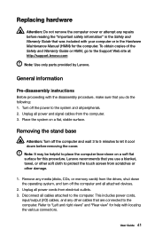
... Guide that was included with locating the various connectors. Note: It may be helpful to the Support Web site at: http://support.lenovo.com Note: Use only parts provided by Lenovo. Unplug all power and signal cables from electrical outlets. 3. Refer to the computer. Unplug all power cords from the computer. 3....Remove any other cables that you use a blanket, towel, or other damage. 1. This includes power cords, input/output (I/O) cables, and any media (disks, CDs, or memory cards) from scratches or other soft cloth to the computer. Disconnect all attached devices...
... Guide that was included with locating the various connectors. Note: It may be helpful to the Support Web site at: http://support.lenovo.com Note: Use only parts provided by Lenovo. Unplug all power and signal cables from electrical outlets. 3. Refer to the computer. Unplug all power cords from the computer. 3....Remove any other cables that you use a blanket, towel, or other damage. 1. This includes power cords, input/output (I/O) cables, and any media (disks, CDs, or memory cards) from scratches or other soft cloth to the computer. Disconnect all attached devices...
Lenovo C3/C4/C5 Series User Guide
Page 47
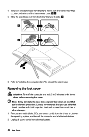
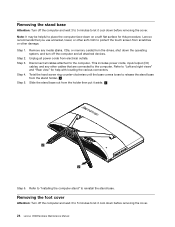
... from scratches or other damage. 1. Unplug all attached devices. 2. 4. Refer to "Installing the computer stand" to place the computer face-down before removing the cover. Lenovo recommends that you use a blanket, towel, or other soft cloth to let it aside. 1 2 3 6. To release the stand base from the stand holder, turn off... cool down on a soft flat surface for this procedure. Note: It may be helpful to reinstall the stand base. Remove any media (disks, CDs, or memory cards) from electrical outlets. 42 User Guide
... from scratches or other damage. 1. Unplug all attached devices. 2. 4. Refer to "Installing the computer stand" to place the computer face-down before removing the cover. Lenovo recommends that you use a blanket, towel, or other soft cloth to let it aside. 1 2 3 6. To release the stand base from the stand holder, turn off... cool down on a soft flat surface for this procedure. Note: It may be helpful to reinstall the stand base. Remove any media (disks, CDs, or memory cards) from electrical outlets. 42 User Guide
Lenovo C3/C4/C5 Series User Guide
Page 48
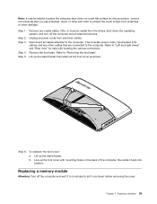
...computer and wait 3 to 5 minutes to let it back into position. Note: It may be helpful to "Removing the foot base". 5. Lenovo recommends that are connected to protect the touch screen from scratches or other soft cloth to the computer. Lift up the stand holder then slide...Remove the foot base. b. Remove any other cables that you use a blanket, towel, or other damage. 1. Lift up the stand holder. Replacing a memory module Attention: Turn off the computer and all cables attached to "Left and right views" and "Rear view" for help with mounting holes on a soft...
...computer and wait 3 to 5 minutes to let it back into position. Note: It may be helpful to "Removing the foot base". 5. Lenovo recommends that are connected to protect the touch screen from scratches or other soft cloth to the computer. Lift up the stand holder then slide...Remove the foot base. b. Remove any other cables that you use a blanket, towel, or other damage. 1. Lift up the stand holder. Replacing a memory module Attention: Turn off the computer and all cables attached to "Left and right views" and "Rear view" for help with mounting holes on a soft...

Lenovo C3/C4/C5 Series User Guide
Page 49
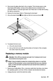
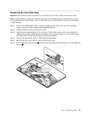
...foot cover and stand base. 44 User Guide Disconnect all cables attached to "Left and right views" and "Rear view" for help with the memory socket, then insert it from its socket. Refer to the computer. Push out the latches on the top edge. Make sure the latches lock ...3. This includes power cords, input/output (I/O) cables, and any other cables that are connected to "Removing the stand base". 5. All of the memory socket to release the memory module and gently pull the memory module upward to "Removing the foot cover". 6. Refer to remove it and push down on both sides of the...
...foot cover and stand base. 44 User Guide Disconnect all cables attached to "Left and right views" and "Rear view" for help with the memory socket, then insert it from its socket. Refer to the computer. Push out the latches on the top edge. Make sure the latches lock ...3. This includes power cords, input/output (I/O) cables, and any other cables that are connected to "Removing the stand base". 5. All of the memory socket to release the memory module and gently pull the memory module upward to "Removing the foot cover". 6. Refer to remove it and push down on both sides of the...
Lenovo C3/C4/C5 Series User Guide
Page 50
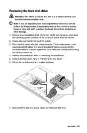
... devices. 2. Disconnect all power cords from electrical outlets. 3. This includes power cords, input/output (I/O) cables, and any media (disks, CDs, or memory cards) from the drives, shut down the operating system, and turn off the computer and wait 3 to 5 minutes to protect the touch screen from...be helpful to the computer. Refer to the computer. Unplug all cables attached to place the computer face-down before removing the cover. Lenovo recommends that are connected to "Left and right views" and "Rear view" for this procedure. Disconnect the data and power cables from ...
... devices. 2. Disconnect all power cords from electrical outlets. 3. This includes power cords, input/output (I/O) cables, and any media (disks, CDs, or memory cards) from the drives, shut down the operating system, and turn off the computer and wait 3 to 5 minutes to protect the touch screen from...be helpful to the computer. Refer to the computer. Unplug all cables attached to place the computer face-down before removing the cover. Lenovo recommends that are connected to "Left and right views" and "Rear view" for this procedure. Disconnect the data and power cables from ...
Lenovo C3/C4/C5 Series User Guide
Page 52
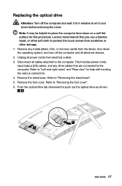
...Disconnect all cables attached to push out the optical drive as shown. 1 2 User Guide 47 Refer to "Removing the foot cover". 6. Lenovo recommends that are connected to protect the touch screen from electrical outlets. 3. Replacing the optical drive Attention: Turn off the computer and all ... flat surface for help with locating the various connectors. 4. This includes power cords, input/output (I/O) cables, and any media (disks, CDs, or memory cards) from the drives, shut down the operating system, and turn off the computer and wait 3 to 5 minutes to "Left and right views"...
...Disconnect all cables attached to push out the optical drive as shown. 1 2 User Guide 47 Refer to "Removing the foot cover". 6. Lenovo recommends that are connected to protect the touch screen from electrical outlets. 3. Replacing the optical drive Attention: Turn off the computer and all ... flat surface for help with locating the various connectors. 4. This includes power cords, input/output (I/O) cables, and any media (disks, CDs, or memory cards) from the drives, shut down the operating system, and turn off the computer and wait 3 to 5 minutes to "Left and right views"...

Lenovo C3/C4/C5 Series User Guide
Page 55
Disconnect the adapter cable from the computer, then unplug the power cord from the drives, shut down the operating system, and turn off the computer and wait 3 to 5 minutes to let it cool down before removing the cover. 1. Connect the new adapter as shown. 50 User Guide Replacing the adapter Attention: Turn off the computer and all attached devices. 2. Remove any media (disks, CDs, or memory cards) from the electrical outlet. 3.
Disconnect the adapter cable from the computer, then unplug the power cord from the drives, shut down the operating system, and turn off the computer and wait 3 to 5 minutes to let it cool down before removing the cover. 1. Connect the new adapter as shown. 50 User Guide Replacing the adapter Attention: Turn off the computer and all attached devices. 2. Remove any media (disks, CDs, or memory cards) from the electrical outlet. 3.

Lenovo C3/C4/C5 Series User Guide
Page 56
... the keyboard: 1. Refer to a USB connector at either side or at the rear of the computer" for the keyboard. Remove any media (disks, CDs, or memory cards) from the drives, shut down the computer, and turn off all power cords from the computer and connect the new keyboard cable to the...
... the keyboard: 1. Refer to a USB connector at either side or at the rear of the computer" for the keyboard. Remove any media (disks, CDs, or memory cards) from the drives, shut down the computer, and turn off all power cords from the computer and connect the new keyboard cable to the...
Lenovo C560 Hardware Maintenance Manual
Page 5
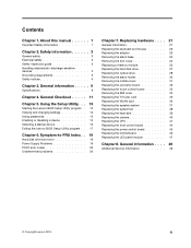
... Replacing the keyboard and mouse 22 Replacing the adapter 22 Removing the stand base 24 Removing the foot cover 24 Replacing a memory module 25 Replacing the hard disk drive 27 Replacing the optical drive 28 Removing the stand holder 30 Removing the middle cover ...Replacing the motherboard 46 Replacing the LED panel module 47 Chapter 8. General information . . . . 49 Additional Service Information 49 © Copyright Lenovo 2013 iii General Checkout . . . . . 11 Chapter 5. Contents Chapter 1. About this manual 1 Important Safety Information 1 Chapter 2. Using the Setup Utility...
... Replacing the keyboard and mouse 22 Replacing the adapter 22 Removing the stand base 24 Removing the foot cover 24 Replacing a memory module 25 Replacing the hard disk drive 27 Replacing the optical drive 28 Removing the stand holder 30 Removing the middle cover ...Replacing the motherboard 46 Replacing the LED panel module 47 Chapter 8. General information . . . . 49 Additional Service Information 49 © Copyright Lenovo 2013 iii General Checkout . . . . . 11 Chapter 5. Contents Chapter 1. About this manual 1 Important Safety Information 1 Chapter 2. Using the Setup Utility...
Lenovo C560 Hardware Maintenance Manual
Page 26
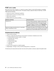
...failing device or component. Undetermined problems 1. a. Repeat steps 1 through 3 until you find a suitable boot device. Extended video memory c. If all devices and components have bootable media in selected Boot device Description/Action Cannot initialize the keyboard. Make sure the ...removed and the problem continues, replace the system board. 20 Lenovo C560Hardware Maintenance Manual Remove or disconnect the following : • Checks some basic motherboard operations • Checks that the memory is working POST Error Message Keyboard error Reboot and Select proper ...
...failing device or component. Undetermined problems 1. a. Repeat steps 1 through 3 until you find a suitable boot device. Extended video memory c. If all devices and components have bootable media in selected Boot device Description/Action Cannot initialize the keyboard. Make sure the ...removed and the problem continues, replace the system board. 20 Lenovo C560Hardware Maintenance Manual Remove or disconnect the following : • Checks some basic motherboard operations • Checks that the memory is working POST Error Message Keyboard error Reboot and Select proper ...

Lenovo C560 Hardware Maintenance Manual
Page 28
..." and "Rear view of the computer. The mouse can be connected to the same connector. Remove any media (disks, CDs, or memory cards) from the computer and connect the new keyboard cable to a USB connector at either side or at the rear of the computer".... Step 2. Step 3. Step 4. Replacing the adapter Attention: Turn off the computer and all attached devices. 22 Lenovo C560Hardware Maintenance Manual Disconnect the defective keyboard cable from the drives, shut down before removing the cover. Step 1. Step 5. Unplug all attached devices...
..." and "Rear view of the computer. The mouse can be connected to the same connector. Remove any media (disks, CDs, or memory cards) from the computer and connect the new keyboard cable to a USB connector at either side or at the rear of the computer".... Step 2. Step 3. Step 4. Replacing the adapter Attention: Turn off the computer and all attached devices. 22 Lenovo C560Hardware Maintenance Manual Disconnect the defective keyboard cable from the drives, shut down before removing the cover. Step 1. Step 5. Unplug all attached devices...
Lenovo C560 Hardware Maintenance Manual
Page 30
..., input/output (I/O) cables, and any media (disks, CDs, or memory cards) from electrical outlets. Step 2. Step 5. Removing the foot cover Attention: Turn off the computer and wait 3 to 5 minutes to let it cool down before removing the cover. 24 Lenovo C560Hardware Maintenance Manual Lenovo recommends that are connected to the computer. Remove any...
..., input/output (I/O) cables, and any media (disks, CDs, or memory cards) from electrical outlets. Step 2. Step 5. Removing the foot cover Attention: Turn off the computer and wait 3 to 5 minutes to let it cool down before removing the cover. 24 Lenovo C560Hardware Maintenance Manual Lenovo recommends that are connected to the computer. Remove any...
Lenovo C560 Hardware Maintenance Manual
Page 31
...attached to the computer. This includes power cords, input/output (I/O) cables, and any media (disks, CDs, or memory cards) from electrical outlets. Note: It may be helpful to place the computer face-down on the back of the... 3. Step 5. Remove the foot base. Lift up the foot cover with locating the various connectors. Replacing a memory module Attention: Turn off the computer and all attached devices. Refer to let it back into position. Line up... the foot cover as shown. Step 2. Chapter 7. Step 4. Lenovo recommends that are connected to "Removing the foot base".
...attached to the computer. This includes power cords, input/output (I/O) cables, and any media (disks, CDs, or memory cards) from electrical outlets. Note: It may be helpful to place the computer face-down on the back of the... 3. Step 5. Remove the foot base. Lift up the foot cover with locating the various connectors. Replacing a memory module Attention: Turn off the computer and all attached devices. Refer to let it back into position. Line up... the foot cover as shown. Step 2. Chapter 7. Step 4. Lenovo recommends that are connected to "Removing the foot base".

Lenovo C560 Hardware Maintenance Manual
Page 32
...scratches or other damage. Refer to "Removing the stand base". Align the new memory module with locating the various connectors. Make sure the latches lock the memory module in place. Lenovo recommends that are connected to the computer. Step 5. Unplug all cables attached to... the computer. Refer to protect the touch screen from electrical outlets. To install a memory module: a. Reattach the foot cover and stand base. 26 Lenovo C560Hardware Maintenance Manual Step 3. Remove the stand base. Refer to "Removing the foot cover". Remove the ...
...scratches or other damage. Refer to "Removing the stand base". Align the new memory module with locating the various connectors. Make sure the latches lock the memory module in place. Lenovo recommends that are connected to the computer. Step 5. Unplug all cables attached to... the computer. Refer to protect the touch screen from electrical outlets. To install a memory module: a. Reattach the foot cover and stand base. 26 Lenovo C560Hardware Maintenance Manual Step 3. Remove the stand base. Refer to "Removing the foot cover". Remove the ...
Lenovo C560 Hardware Maintenance Manual
Page 33
... with locating the various connectors. Step 1. This includes power cords, input/output (I/O) cables, and any media (disks, CDs, or memory cards) from the drives, shut down before removing the cover. Step 4. Step 5. Lenovo recommends that are connected to "Removing the foot cover". Refer to protect the touch screen from electrical outlets. Replacing...
... with locating the various connectors. Step 1. This includes power cords, input/output (I/O) cables, and any media (disks, CDs, or memory cards) from the drives, shut down before removing the cover. Step 4. Step 5. Lenovo recommends that are connected to "Removing the foot cover". Refer to protect the touch screen from electrical outlets. Replacing...


