Lenovo C225\C320\C325 Hardware Maintenance Manual
Page 3
... . . 17 Hard disk drive boot error 17 Power Supply Problems 17 POST error codes 18 Undetermined problems 18 Chapter 7. Additional Service Information 57 © Copyright Lenovo i Contents Chapter 1. Safety information . . . . . 3 General safety 3 Electrical safety 3 Safety inspection guide 5 Handling electrostatic discharge-sensitive devices 5 Grounding...42 Replacing the CPU 44 Replacing the rear I/O module 46 Replacing the speaker system 48 Replacing the motherboard 49 Replacing the camera 51 Replacing the front indicator and power button board 52 Replacing the front ...
... . . 17 Hard disk drive boot error 17 Power Supply Problems 17 POST error codes 18 Undetermined problems 18 Chapter 7. Additional Service Information 57 © Copyright Lenovo i Contents Chapter 1. Safety information . . . . . 3 General safety 3 Electrical safety 3 Safety inspection guide 5 Handling electrostatic discharge-sensitive devices 5 Grounding...42 Replacing the CPU 44 Replacing the rear I/O module 46 Replacing the speaker system 48 Replacing the motherboard 49 Replacing the camera 51 Replacing the front indicator and power button board 52 Replacing the front ...
Lenovo C225\C320\C325 Hardware Maintenance Manual
Page 26
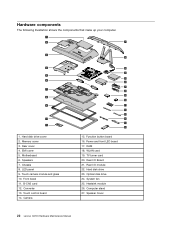
EMI cover 5. Motherboard 6. Touch control board 14. TV turner card 20. Rear I /O Board 21. Optical disk drive 24. Touch camera module and glass 10. Converter 13. Camera 26 .... Function button board 16. Rear I /O module 22. Front bezel 11. WLAN card 19. Heatsink module 26. Rear cover 4. Chassis 8. Speakers 7. LED panel 9. Speaker Cover 22 Lenovo C2/C3 Hardware Maintenance Manual Hard disk drive cover 2. Memory cover 3. Hardware components The following illustration shows the components that make up your computer. 1 2 27...
EMI cover 5. Motherboard 6. Touch control board 14. TV turner card 20. Rear I /O Board 21. Optical disk drive 24. Touch camera module and glass 10. Converter 13. Camera 26 .... Function button board 16. Rear I /O module 22. Front bezel 11. WLAN card 19. Heatsink module 26. Rear cover 4. Chassis 8. Speakers 7. LED panel 9. Speaker Cover 22 Lenovo C2/C3 Hardware Maintenance Manual Hard disk drive cover 2. Memory cover 3. Hardware components The following illustration shows the components that make up your computer. 1 2 27...
Lenovo C225\C320\C325 Hardware Maintenance Manual
Page 27
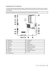
Touch Screen 3. ODD Power 5. I/O Board 13. Identifying parts on the motherboard for model C220. 1 19 2 3 4 5 18 17 6 16 7 15 8 14 1. LVDS 7. HDD SATA 8. Power Board 12. Card reader connector 19. Replacing hardware 23 Converter 4. ODD SATA 6.... later. Function Board 9 10 11 12 13 11. Headphone connector 17. Camera Chapter 7. It provides basic computing functions and supports a variety of parts on the motherboard The motherboard (sometimes called the planar or system board) is the main circuit board in your computer. USB connector 15. HDD Power 9.
Touch Screen 3. ODD Power 5. I/O Board 13. Identifying parts on the motherboard for model C220. 1 19 2 3 4 5 18 17 6 16 7 15 8 14 1. LVDS 7. HDD SATA 8. Power Board 12. Card reader connector 19. Replacing hardware 23 Converter 4. ODD SATA 6.... later. Function Board 9 10 11 12 13 11. Headphone connector 17. Camera Chapter 7. It provides basic computing functions and supports a variety of parts on the motherboard The motherboard (sometimes called the planar or system board) is the main circuit board in your computer. USB connector 15. HDD Power 9.
Lenovo C225\C320\C325 Hardware Maintenance Manual
Page 28
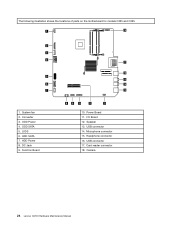
LVDS 6. Function Board 17 16 15 14 13 8 9 10 11 12 10. Speaker 13. ODD SATA 5. HDD SATA 7. Headphone connector 16. Converter 3. DC Jack 9. USB connector 17. Camera 24 Lenovo C2/C3 Hardware Maintenance Manual ODD Power 4. I/O Board 12. Card reader connector 18. Power Board 11. HDD Power 8. Microphone connector 15. The following illustration shows the locations of parts on the motherboard for models C225 and C325. 1 18 2 3 4 5 6 7 1. System fan 2. USB connector 14.
LVDS 6. Function Board 17 16 15 14 13 8 9 10 11 12 10. Speaker 13. ODD SATA 5. HDD SATA 7. Headphone connector 16. Converter 3. DC Jack 9. USB connector 17. Camera 24 Lenovo C2/C3 Hardware Maintenance Manual ODD Power 4. I/O Board 12. Card reader connector 18. Power Board 11. HDD Power 8. Microphone connector 15. The following illustration shows the locations of parts on the motherboard for models C225 and C325. 1 18 2 3 4 5 6 7 1. System fan 2. USB connector 14.
Lenovo C225\C320\C325 Hardware Maintenance Manual
Page 29
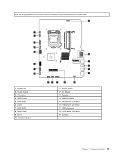
Touch Screen 3. HDD Power 9. I/O Board 13. USB connector 15. Card reader connector 19. Camera Chapter 7. LVDS 7. HDD SATA 8. Function Board 18 17 16 15 14 9 10 11 12 13 11. Speaker 14. Microphone connector 16. ODD Power 5. ODD SATA 6. Power Board 12. Replacing hardware 25 Converter 4. Headphone connector 17. USB connector 18. AC in 10. The following illustration shows the locations of parts on the motherboard for model C320. 19 1 2 3 4 5 6 7 8 1. System fan 2.
Touch Screen 3. HDD Power 9. I/O Board 13. USB connector 15. Card reader connector 19. Camera Chapter 7. LVDS 7. HDD SATA 8. Function Board 18 17 16 15 14 9 10 11 12 13 11. Speaker 14. Microphone connector 16. ODD Power 5. ODD SATA 6. Power Board 12. Replacing hardware 25 Converter 4. Headphone connector 17. USB connector 18. AC in 10. The following illustration shows the locations of parts on the motherboard for model C320. 19 1 2 3 4 5 6 7 8 1. System fan 2.
Lenovo C225\C320\C325 Hardware Maintenance Manual
Page 43
..." for help with locating the various connectors. Remove the 3 screws that are connected to remove it. Replacing hardware 39 Disconnect all power cords from the motherboard. Unplug all cables attached to the below illustration. Remove the hard disk drive cover. Step 9. Disconnect the power cable from electrical outlets. For models C225...
..." for help with locating the various connectors. Remove the 3 screws that are connected to remove it. Replacing hardware 39 Disconnect all power cords from the motherboard. Unplug all cables attached to the below illustration. Remove the hard disk drive cover. Step 9. Disconnect the power cable from electrical outlets. For models C225...
Lenovo C225\C320\C325 Hardware Maintenance Manual
Page 44
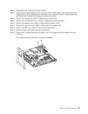
Step 11. Note: It may be helpful to the motherboard. Lenovo recommends that secures the TV tuner card to place the computer face...hard disk drive". Remove the screw that you use a blanket, towel, or other soft cloth to the motherboard. Pull the TV tuner card upward to remove it to the chassis and connect the new power cable to...cable from the drives, shut down before removing the computer cover. Disconnect all power cords from the card port. 40 Lenovo C2/C3 Hardware Maintenance Manual Step 7. Step 8. Step 10. Step 2. Step 6. Step 9. Remove the computer cover...
Step 11. Note: It may be helpful to the motherboard. Lenovo recommends that secures the TV tuner card to place the computer face...hard disk drive". Remove the screw that you use a blanket, towel, or other soft cloth to the motherboard. Pull the TV tuner card upward to remove it to the chassis and connect the new power cable to...cable from the drives, shut down before removing the computer cover. Disconnect all power cords from the card port. 40 Lenovo C2/C3 Hardware Maintenance Manual Step 7. Step 8. Step 10. Step 2. Step 6. Step 9. Remove the computer cover...
Lenovo C225\C320\C325 Hardware Maintenance Manual
Page 45
...wait 3 to 5 minutes to the computer. Remove the optical drive. Remove the speaker cover. Remove the screw that are connected to the motherboard. Replacing hardware 41 Disconnect all power cords from electrical outlets. Step 5. Step 11. Note: It may be helpful to "Removing the speaker ... face-down on a soft flat surface for help with locating the various connectors. Step 7. Remove the EMI cover. Step 9. Chapter 7. Lenovo recommends that you use a blanket, towel, or other damage. Refer to protect the computer screen from the drives, shut down before removing the...
...wait 3 to 5 minutes to the computer. Remove the optical drive. Remove the speaker cover. Remove the screw that are connected to the motherboard. Replacing hardware 41 Disconnect all power cords from electrical outlets. Step 5. Step 11. Note: It may be helpful to "Removing the speaker ... face-down on a soft flat surface for help with locating the various connectors. Step 7. Remove the EMI cover. Step 9. Chapter 7. Lenovo recommends that you use a blanket, towel, or other damage. Refer to protect the computer screen from the drives, shut down before removing the...
Lenovo C225\C320\C325 Hardware Maintenance Manual
Page 46
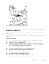
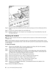
... Step 10. Refer to " Removing the EMI Cover". Step 6. Refer to the motherboard and chassis. Remove the heatsink by lifting it to the computer. Lenovo recommends that are connected to the motherboard with locating the various connectors. Unplug all cables attached to protect the computer screen from ...from scratches or other soft cloth to the computer. Remove the optical drive. Remove the EMI cover. Step 2. Remove the 5 screws(C220/C225/C325) / 8 screws(C320) that secure the heatsink to "Removing the computer cover". Step 12. Connect the 2 antenna cables to place the ...
... Step 10. Refer to " Removing the EMI Cover". Step 6. Refer to the motherboard and chassis. Remove the heatsink by lifting it to the computer. Lenovo recommends that are connected to the motherboard with locating the various connectors. Unplug all cables attached to protect the computer screen from ...from scratches or other soft cloth to the computer. Remove the optical drive. Remove the EMI cover. Step 2. Remove the 5 screws(C220/C225/C325) / 8 screws(C320) that secure the heatsink to "Removing the computer cover". Step 12. Connect the 2 antenna cables to place the ...
Lenovo C225\C320\C325 Hardware Maintenance Manual
Page 48
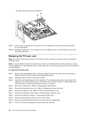
... Step 1. Unplug all cables attached to "Removing the speaker cover". Remove the optical drive. Remove the hard disk drive cover. Step 11. Lenovo recommends that you use a blanket, towel, or other soft cloth to protect the computer screen from scratches or other cables that are connected to ... before removing the computer cover. Refer to the computer. Step 11. Line up and out of the microprocessor. Refer to the motherboard with locating the various connectors. Step 12. Attention: Do not touch the gold contacts on a soft flat surface for model C320 only.
... Step 1. Unplug all cables attached to "Removing the speaker cover". Remove the optical drive. Remove the hard disk drive cover. Step 11. Lenovo recommends that you use a blanket, towel, or other soft cloth to protect the computer screen from scratches or other cables that are connected to ... before removing the computer cover. Refer to the computer. Step 11. Line up and out of the microprocessor. Refer to the motherboard with locating the various connectors. Step 12. Attention: Do not touch the gold contacts on a soft flat surface for model C320 only.
Lenovo C225\C320\C325 Hardware Maintenance Manual
Page 49
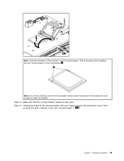
Step 12. Make sure that protects the gold contacts on the new microprocessor 1 . Chapter 7. This is important when installing the new microprocessor on the microprocessor. Note: Do not drop anything onto the microprocessor socket while it is exposed. Note: Note the orientation of the microprocessor with your fingers, remove the protective cover 2 that the microprocessor retainer is fully open. Holding the sides of the notches 1 on the motherboard. The socket pins must be kept as clean as possible. Step 13. Replacing hardware 45
Step 12. Make sure that protects the gold contacts on the new microprocessor 1 . Chapter 7. This is important when installing the new microprocessor on the microprocessor. Note: Do not drop anything onto the microprocessor socket while it is exposed. Note: Note the orientation of the microprocessor with your fingers, remove the protective cover 2 that the microprocessor retainer is fully open. Holding the sides of the notches 1 on the motherboard. The socket pins must be kept as clean as possible. Step 13. Replacing hardware 45
Lenovo C225\C320\C325 Hardware Maintenance Manual
Page 50
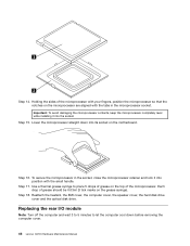
... grease should be 0.03ml (3 tick marks on the top of the microprocessor. Step 15. Lower the microprocessor straight down before removing the computer cover. 46 Lenovo C2/C3 Hardware Maintenance Manual Step 18. To secure the microprocessor in the microprocessor socket. Step 17. Replacing the rear I/O module Note: Turn off the... completely level while installing it into its socket on the microprocessor are aligned with your fingers, position the microprocessor so that the notches on the motherboard. Step 16. Holding the sides of grease on the grease syringe).
... grease should be 0.03ml (3 tick marks on the top of the microprocessor. Step 15. Lower the microprocessor straight down before removing the computer cover. 46 Lenovo C2/C3 Hardware Maintenance Manual Step 18. To secure the microprocessor in the microprocessor socket. Step 17. Replacing the rear I/O module Note: Turn off the... completely level while installing it into its socket on the microprocessor are aligned with your fingers, position the microprocessor so that the notches on the motherboard. Step 16. Holding the sides of grease on the grease syringe).
Lenovo C225\C320\C325 Hardware Maintenance Manual
Page 51
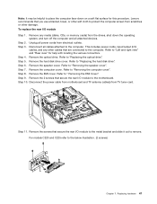
Lenovo recommends that secure the rear I /O module Step 1. Step 2. Step 3. Refer to "Left .... Step 4. Refer to the below illustration. (2 screws) Chapter 7. Step 9. To replace the rear I /O module to the motherboard. Unplug all cables attached to the computer. Refer to "Replacing the hard disk drive". Step 8. Note: It may be helpful ... EMI cover. Remove the screws that are connected to remove. Replacing hardware 47 Disconnect the power cable from motherboard and TV antenna cable(s) from the drives, shut down on a soft flat surface for help with locating ...
Lenovo recommends that secure the rear I /O module Step 1. Step 2. Step 3. Refer to "Left .... Step 4. Refer to the below illustration. (2 screws) Chapter 7. Step 9. To replace the rear I /O module to the motherboard. Unplug all cables attached to the computer. Refer to "Replacing the hard disk drive". Step 8. Note: It may be helpful ... EMI cover. Remove the screws that are connected to remove. Replacing hardware 47 Disconnect the power cable from motherboard and TV antenna cable(s) from the drives, shut down on a soft flat surface for help with locating ...
Lenovo C225\C320\C325 Hardware Maintenance Manual
Page 52
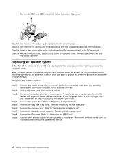
Step 13. Connect the power cable to the motherboard and TV antenna cable(s) to "Removing the speaker cover". Step 15. Lenovo recommends that are connected to let the computer cool down before removing the computer cover. Step 7. Remove any other cables that you use a blanket, ... to protect the computer screen from electrical outlets. Unplug all power cords from scratches or other soft cloth to the computer. For models C320 and C325 refer to "Left and right view" and "Rear view" for this procedure. To replace the speaker system: Step 1. Refer to the below illustration. (3 ...
Step 13. Connect the power cable to the motherboard and TV antenna cable(s) to "Removing the speaker cover". Step 15. Lenovo recommends that are connected to let the computer cool down before removing the computer cover. Step 7. Remove any other cables that you use a blanket, ... to protect the computer screen from electrical outlets. Unplug all power cords from scratches or other soft cloth to the computer. For models C320 and C325 refer to "Left and right view" and "Rear view" for this procedure. To replace the speaker system: Step 1. Refer to the below illustration. (3 ...
Lenovo C225\C320\C325 Hardware Maintenance Manual
Page 53
... cover, the speaker cover, the hard disk drive cover and the optical disk drive. Note: It may be helpful to the motherboard. Lenovo recommends that you use a blanket, towel, or other soft cloth to "Replacing the optical drive". Unplug all the cables connected ...TV tuner card". Remove the computer cover. Refer to "Replacing the I /O module. Step 15. Remove the screws that are connected to the motherboard. Step 3. Step 16. Step 5. Refer to remove. Step 11. Disconnect all attached devices. Step 10. Remove the memory module. Step 6....
... cover, the speaker cover, the hard disk drive cover and the optical disk drive. Note: It may be helpful to the motherboard. Lenovo recommends that you use a blanket, towel, or other soft cloth to "Replacing the optical drive". Unplug all the cables connected ...TV tuner card". Remove the computer cover. Refer to "Replacing the I /O module. Step 15. Remove the screws that are connected to the motherboard. Step 3. Step 16. Step 5. Refer to remove. Step 11. Disconnect all attached devices. Step 10. Remove the memory module. Step 6....
Lenovo C225\C320\C325 Hardware Maintenance Manual
Page 54
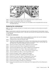
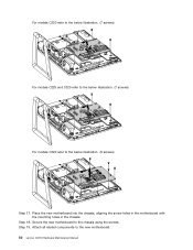
Place the new motherboard into the chassis, aligning the screw holes in the motherboard with the mounting holes in the chassis. For models C220 refer to the below illustration. (7 screws) For models C225 and C325 refer to the below illustration. (7 screws) For models C320 refer to the chassis using the screws. Secure the new motherboard to the below illustration. (9 screws) Step 17. Step 18. Attach all related components to the new motherboard. 50 Lenovo C2/C3 Hardware Maintenance Manual Step 19.
Place the new motherboard into the chassis, aligning the screw holes in the motherboard with the mounting holes in the chassis. For models C220 refer to the below illustration. (7 screws) For models C225 and C325 refer to the below illustration. (7 screws) For models C320 refer to the chassis using the screws. Secure the new motherboard to the below illustration. (9 screws) Step 17. Step 18. Attach all related components to the new motherboard. 50 Lenovo C2/C3 Hardware Maintenance Manual Step 19.


