Hardware Maintenance Manual
Page 5
...Lenovo Solution Center 30 ThinkVantage Productivity Center 30 Access Help 30 Additional information resources 31 Specifications 32 For machine types: 3063, 3231, 3285, 4084, 4085, 4086, 4087, 6138, 6209, 6239, 6302, 7188, 7244, 7347, 7355, 7358, 7373, 7484, 7571, 7628, 7635, 7639, 8494, 8854, 9728, 9960... cover 73 Locating components 75 Locating parts on the system board 76 Removing and reinstalling the front bezel . . . . 77 Replacing a memory module 78 Replacing the power supply 79 Replacing the heat sink and fan assembly . . . . 80 Replacing the microprocessor 81 Replacing the ...
...Lenovo Solution Center 30 ThinkVantage Productivity Center 30 Access Help 30 Additional information resources 31 Specifications 32 For machine types: 3063, 3231, 3285, 4084, 4085, 4086, 4087, 6138, 6209, 6239, 6302, 7188, 7244, 7347, 7355, 7358, 7373, 7484, 7571, 7628, 7635, 7639, 8494, 8854, 9728, 9960... cover 73 Locating components 75 Locating parts on the system board 76 Removing and reinstalling the front bezel . . . . 77 Replacing a memory module 78 Replacing the power supply 79 Replacing the heat sink and fan assembly . . . . 80 Replacing the microprocessor 81 Replacing the ...
Hardware Maintenance Manual
Page 6
..., 7347, 7355, 7358, 7373, 7484, 7571, 7628, 7635, 7639, 8494, 8854, 9728, 9960, and 9965 133 Mechanical FRUs 168 Keyboard and Mouse 180 Adapters and miscellaneous FRUs 214 Power Cords 221 ... Professional 32 SP1 Recovery CD 529 Windows 7 Professional 64 Recovery CD . . 539 iv ThinkCentre Hardware Maintenance Manual Replacing the diskette drive 95 Replacing the front fan assembly 96 Replacing the... components 109 Locating parts on the system board 110 Replacing the battery 110 Replacing a memory module 112 Replacing an adapter card 113 Replacing the power supply 115 Replacing the heat...
..., 7347, 7355, 7358, 7373, 7484, 7571, 7628, 7635, 7639, 8494, 8854, 9728, 9960, and 9965 133 Mechanical FRUs 168 Keyboard and Mouse 180 Adapters and miscellaneous FRUs 214 Power Cords 221 ... Professional 32 SP1 Recovery CD 529 Windows 7 Professional 64 Recovery CD . . 539 iv ThinkCentre Hardware Maintenance Manual Replacing the diskette drive 95 Replacing the front fan assembly 96 Replacing the... components 109 Locating parts on the system board 110 Replacing the battery 110 Replacing a memory module 112 Replacing an adapter card 113 Replacing the power supply 115 Replacing the heat...
Hardware Maintenance Manual
Page 56
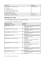
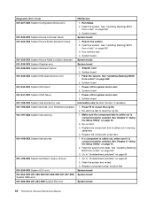
... board 1. See "Updating (flashing) BIOS from a disc" on switch for continuity. Run Setup 2. Flash the system. Reboot the system 2. Run memory test 4. System board 1. System board 1. Check/Verify Check the following index, X can represent any number. Check the power-on page 560 2. ...the diagnostic tests. Flash the system. See "Updating (flashing) BIOS from a disc" on page 560 3. System board 1. System board 48 ThinkCentre Hardware Maintenance Manual See "Updating (flashing) BIOS from a disc" on page 560 3. Flash the system. See "Running tests" on page 39...
... board 1. See "Updating (flashing) BIOS from a disc" on switch for continuity. Run Setup 2. Flash the system. Reboot the system 2. Run memory test 4. System board 1. System board 1. Check/Verify Check the following index, X can represent any number. Check the power-on page 560 2. ...the diagnostic tests. Flash the system. See "Updating (flashing) BIOS from a disc" on page 560 3. System board 1. System board 48 ThinkCentre Hardware Maintenance Manual See "Updating (flashing) BIOS from a disc" on page 560 3. Flash the system. See "Running tests" on page 39...
Hardware Maintenance Manual
Page 58
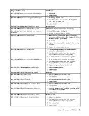
... 2. System board 1. Press F3 to reset the log file 1. See Chapter 6 "Using the Setup Utility" on system and re-test 2. Run memory test 4. System board System board System board 1. System board 1. Power-off /on page 560 3. Power-off /on page 43 2. Re-start ... BIOS from a disc" on page 69 2. Re-run test 3. Replace the component under function test System board System board System board 50 ThinkCentre Hardware Maintenance Manual Go to "Undetermined problems" on page 560 2. System board Information only Re-start the test to review the log file 2....
... 2. System board 1. Press F3 to reset the log file 1. See Chapter 6 "Using the Setup Utility" on system and re-test 2. Run memory test 4. System board System board System board 1. System board 1. Power-off /on page 560 3. Power-off /on page 43 2. Re-start ... BIOS from a disc" on page 69 2. Re-run test 3. Replace the component under function test System board System board System board 50 ThinkCentre Hardware Maintenance Manual Go to "Undetermined problems" on page 560 2. System board Information only Re-start the test to review the log file 2....
Hardware Maintenance Manual
Page 63
... 2. Wrap plug 2. See Chapter 6 "Using the Setup Utility" on page 560 2. System board No action 1. See "Updating (flashing) BIOS from a disc" on page 43 2. Run memory test 4. Symptom-to-FRU index 55
... 2. Wrap plug 2. See Chapter 6 "Using the Setup Utility" on page 560 2. System board No action 1. See "Updating (flashing) BIOS from a disc" on page 43 2. Run memory test 4. Symptom-to-FRU index 55
Hardware Maintenance Manual
Page 72
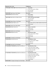
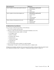
...board No action 1. CD-ROM Drive Cable 2. Hard Disk Drive Cable 2. System board 1. Hard Disk drive (SCSI) 5. System board 1. Assure Asset Security Enabled 2. Replace the memory module called out by the test 2. Cache, if removable 2. System board 3. Check power supply voltages 3. Check power supply voltages 3. CD-ROM drive 4. System board No... Cartridge Drive Test Passed FRU/Action 1. Reseat the hard disk drive cable 4. Hard Disk Drive Cable 2. Microprocessor No action 1. System board No action 64 ThinkCentre Hardware Maintenance Manual System board No action 1.
...board No action 1. CD-ROM Drive Cable 2. Hard Disk Drive Cable 2. System board 1. Hard Disk drive (SCSI) 5. System board 1. Assure Asset Security Enabled 2. Replace the memory module called out by the test 2. Cache, if removable 2. System board 3. Check power supply voltages 3. Check power supply voltages 3. CD-ROM drive 4. System board No... Cartridge Drive Test Passed FRU/Action 1. Reseat the hard disk drive cable 4. Hard Disk Drive Cable 2. Microprocessor No action 1. System board No action 64 ThinkCentre Hardware Maintenance Manual System board No action 1.
Hardware Maintenance Manual
Page 74
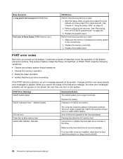
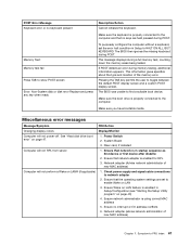
... settings. POST Error Message CMOS battery failed Description/Action The CMOS battery is set to NONE. 66 ThinkCentre Hardware Maintenance Manual CMOS checksum error - Checksum of three beeps DRAM memory error FRU/Action Perform the following actions in Setup is no longer functional. CPU at nnnn Press Esc...not appear on the screen the next time you correct the cause of the system and some basic system-board operations • Checks the memory operation • Starts the video operation • Verifies that CMOS has become corrupt due to Save and exit. When you turn on the...
... settings. POST Error Message CMOS battery failed Description/Action The CMOS battery is set to NONE. 66 ThinkCentre Hardware Maintenance Manual CMOS checksum error - Checksum of three beeps DRAM memory error FRU/Action Perform the following actions in Setup is no longer functional. CPU at nnnn Press Esc...not appear on the screen the next time you correct the cause of the system and some basic system-board operations • Checks the memory operation • Starts the video operation • Verifies that CMOS has become corrupt due to Save and exit. When you turn on the...
Hardware Maintenance Manual
Page 75
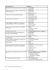
...drive is properly connected to the computer and that the operating system settings are held pressed during a full memory test, counting down the memory areas being tested. Make sure you have bootable media. Miscellaneous error messages Message/Symptom FRU/Action Changing display... the computer without a keyboard, set to find a suitable boot device. System Board 3. Network adapter (advise network administrator of the memory error. Riser card, if installed Computer will not power-off. Network adapter (Advise network administrator of new MAC address) Computer will not...
...drive is properly connected to the computer and that the operating system settings are held pressed during a full memory test, counting down the memory areas being tested. Make sure you have bootable media. Miscellaneous error messages Message/Symptom FRU/Action Changing display... the computer without a keyboard, set to find a suitable boot device. System Board 3. Network adapter (advise network administrator of the memory error. Riser card, if installed Computer will not power-off. Network adapter (Advise network administrator of new MAC address) Computer will not...
Hardware Maintenance Manual
Page 76
Power Supply 2. Diskette Drive Cable Flashing cursor with a known-good diagnostic diskette. 1. Hard Disk Drive Cable Incorrect memory size during POST 1. Network Adapter Intensity or color varies from server 1. Video adapter (if present) 3. Non-...If network administrator is active. 1. System Board Diskette drive in -use light remains on page 47. Memory Module 3. Display 2. Diskette Drive Cable 4. Check the network adapter LED status 68 ThinkCentre Hardware Maintenance Manual Diskette Drive 2. Diskette Drive Cable 3. Display 2. System Board Power-on indicator or ...
Power Supply 2. Diskette Drive Cable Flashing cursor with a known-good diagnostic diskette. 1. Hard Disk Drive Cable Incorrect memory size during POST 1. Network Adapter Intensity or color varies from server 1. Video adapter (if present) 3. Non-...If network administrator is active. 1. System Board Diskette drive in -use light remains on page 47. Memory Module 3. Display 2. Diskette Drive Cable 4. Check the network adapter LED status 68 ThinkCentre Hardware Maintenance Manual Diskette Drive 2. Diskette Drive Cable 3. Display 2. System Board Power-on indicator or ...
Hardware Maintenance Manual
Page 77
..." on the power and the computer to -FRU index 69 Cable 4. System Board 1. Keyboard Cable 3. Memory modules d. Extended video memory e. External Cache f. External Device Self-Test OK? 2. External Device 3. Symptom-to re-test the system. 4. External Cache RAM g. Hard disk drive h. Repeat steps 1 through 3 until you encounter undetermined problems, do not work FRU...
..." on the power and the computer to -FRU index 69 Cable 4. System Board 1. Keyboard Cable 3. Memory modules d. Extended video memory e. External Cache f. External Device Self-Test OK? 2. External Device 3. Symptom-to re-test the system. 4. External Cache RAM g. Hard disk drive h. Repeat steps 1 through 3 until you encounter undetermined problems, do not work FRU...
Hardware Maintenance Manual
Page 83
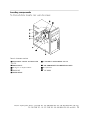
Component locations 1 Microprocessor, heat sink, and heat sink fan assembly 2 Memory slots (4) 3 PCI Express x1 adapter card slot 4 Adapter card 5 Adapter card slot 6 PCI Express x16 graphics adapter card slot 7 Cover presence switch (also called intrusion ...: 3063, 3231, 3285, 4084, 4085, 4086, 4087, 6138, 6209, 6239, 6302, 7188, 7244, 7347, 7355, 7358, 7373, 7484, 7571, 7628, 7635, 7639, 8494, 8854, 9728, 9960, and 9965.) 75
Component locations 1 Microprocessor, heat sink, and heat sink fan assembly 2 Memory slots (4) 3 PCI Express x1 adapter card slot 4 Adapter card 5 Adapter card slot 6 PCI Express x16 graphics adapter card slot 7 Cover presence switch (also called intrusion ...: 3063, 3231, 3285, 4084, 4085, 4086, 4087, 6138, 6209, 6239, 6302, 7188, 7244, 7347, 7355, 7358, 7373, 7484, 7571, 7628, 7635, 7639, 8494, 8854, 9728, 9960, and 9965.) 75
Hardware Maintenance Manual
Page 84
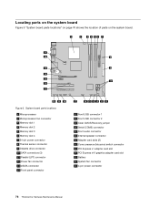
Figure 5. System board parts locations 1 Microprocessor 2 Microprocessor fan connector 3 Memory slot 1 4 Memory slot 2 5 Memory slot 3 6 Memory slot 4 7 24-pin power connector 8 Thermal sensor connector 9 Diskette drive connector 10 SATA connectors (3) 11 Parallel (LPT) connector 12 Power fan ...Express x1 adapter card slot 24 PCI Express x16 graphics adapter card slot 25 Battery 26 System fan connector 27 4-pin power connector 76 ThinkCentre Hardware Maintenance Manual Locating parts on the system board Figure 5 "System board parts locations" on page 76 shows the location of parts on...
Figure 5. System board parts locations 1 Microprocessor 2 Microprocessor fan connector 3 Memory slot 1 4 Memory slot 2 5 Memory slot 3 6 Memory slot 4 7 24-pin power connector 8 Thermal sensor connector 9 Diskette drive connector 10 SATA connectors (3) 11 Parallel (LPT) connector 12 Power fan ...Express x1 adapter card slot 24 PCI Express x16 graphics adapter card slot 25 Battery 26 System fan connector 27 4-pin power connector 76 ThinkCentre Hardware Maintenance Manual Locating parts on the system board Figure 5 "System board parts locations" on page 76 shows the location of parts on...
Hardware Maintenance Manual
Page 86
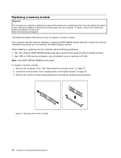
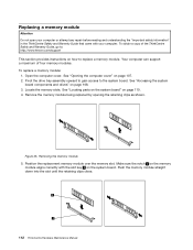
...or replacing DDR3 DIMMs (double data rate 3 dual inline memory modules) that came with your computer or attempt any combination up to a maximum of 8 GB of the ThinkCentre Safety and Warranty Guide, go to: http://www.lenovo.com/support This section provides instructions on how to a... maximum of 8 GB. To obtain a copy of system memory. To replace a memory module: 1. Remove the memory module being replaced by opening the ...
...or replacing DDR3 DIMMs (double data rate 3 dual inline memory modules) that came with your computer or attempt any combination up to a maximum of 8 GB of the ThinkCentre Safety and Warranty Guide, go to: http://www.lenovo.com/support This section provides instructions on how to a... maximum of 8 GB. To obtain a copy of system memory. To replace a memory module: 1. Remove the memory module being replaced by opening the ...
Hardware Maintenance Manual
Page 87
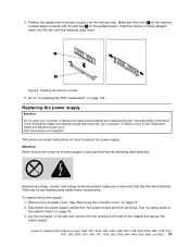
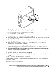
... the notch 1 on the memory module aligns correctly with your computer or attempt any part that came with the slot key 2 on its side and remove the four screws at the rear of the ThinkCentre Safety and Warranty Guide, go to: http://www.lenovo.com/support This section provides ...3285, 4084, 4085, 4086, 4087, 6138, 6209, 6239, 6302, 7188, 7244, 7347, 7355, 7358, 7373, 7484, 7571, 7628, 7635, 7639, 8494, 8854, 9728, 9960, and 9965.) 79 Replacing the power supply Attention Do not open your computer. There are present inside these components. Remove the computer cover. Disconnect the...
... the notch 1 on the memory module aligns correctly with your computer or attempt any part that came with the slot key 2 on its side and remove the four screws at the rear of the ThinkCentre Safety and Warranty Guide, go to: http://www.lenovo.com/support This section provides ...3285, 4084, 4085, 4086, 4087, 6138, 6209, 6239, 6302, 7188, 7244, 7347, 7355, 7358, 7373, 7484, 7571, 7628, 7635, 7639, 8494, 8854, 9728, 9960, and 9965.) 79 Replacing the power supply Attention Do not open your computer. There are present inside these components. Remove the computer cover. Disconnect the...
Hardware Maintenance Manual
Page 93
... parts on the system board" on page 78. 10. Go to the system board. Carefully take note of the location of the chassis. 9. Remove the memory modules from the failing system board and install it in the chassis. Reinstall the heat sink and fan assembly. Reconnect all cables. The failing system...: 3063, 3231, 3285, 4084, 4085, 4086, 4087, 6138, 6209, 6239, 6302, 7188, 7244, 7347, 7355, 7358, 7373, 7484, 7571, 7628, 7635, 7639, 8494, 8854, 9728, 9960, and 9965.) 85 Remove the heat sink and fan assembly from the rear of the failing system board and install it on the new system...
... parts on the system board" on page 78. 10. Go to the system board. Carefully take note of the location of the chassis. 9. Remove the memory modules from the failing system board and install it in the chassis. Reinstall the heat sink and fan assembly. Reconnect all cables. The failing system...: 3063, 3231, 3285, 4084, 4085, 4086, 4087, 6138, 6209, 6239, 6302, 7188, 7244, 7347, 7355, 7358, 7373, 7484, 7571, 7628, 7635, 7639, 8494, 8854, 9728, 9960, and 9965.) 85 Remove the heat sink and fan assembly from the rear of the failing system board and install it on the new system...
Hardware Maintenance Manual
Page 94
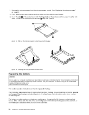
...retainer and lock it into position. The battery normally requires no battery lasts forever. Your computer has a special type of memory that came with the small handle. 3. If the battery fails, the date, time, and configuration information (including passwords)...parallel-port assignments (configuration). See "Replacing the microprocessor" on how to : http://www.lenovo.com/support This section provides instructions on page 81. 2. Tabs on the computer. 86 ThinkCentre Hardware Maintenance Manual however, no charging or maintenance throughout its life; 1. Remove the microprocessor...
...retainer and lock it into position. The battery normally requires no battery lasts forever. Your computer has a special type of memory that came with the small handle. 3. If the battery fails, the date, time, and configuration information (including passwords)...parallel-port assignments (configuration). See "Replacing the microprocessor" on how to : http://www.lenovo.com/support This section provides instructions on page 81. 2. Tabs on the computer. 86 ThinkCentre Hardware Maintenance Manual however, no charging or maintenance throughout its life; 1. Remove the microprocessor...
Hardware Maintenance Manual
Page 117
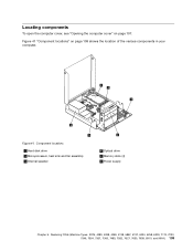
Figure 41 "Component locations" on page 107. Locating components To open the computer cover, see "Opening the computer cover" on page 109 shows the location of the various components in your computer. Figure 41. Replacing FRUs (Machine Types: 3379, 4083, 4088, 4099, 4138, 5897, 6137, 6234, 6258, 6303, 7174, 7220, 7346, 7354, 7357, 7360, 7483, 7582, 7627, 7630, 7638, 8910, and 9964.) 109 Component locations 1 Hard disk drive 2 Microprocessor, heat sink and fan assembly 3 Internal speaker 4 Optical drive 5 Memory slots (4) 6 Power supply Chapter 9.
Figure 41 "Component locations" on page 107. Locating components To open the computer cover, see "Opening the computer cover" on page 109 shows the location of the various components in your computer. Figure 41. Replacing FRUs (Machine Types: 3379, 4083, 4088, 4099, 4138, 5897, 6137, 6234, 6258, 6303, 7174, 7220, 7346, 7354, 7357, 7360, 7483, 7582, 7627, 7630, 7638, 8910, and 9964.) 109 Component locations 1 Hard disk drive 2 Microprocessor, heat sink and fan assembly 3 Internal speaker 4 Optical drive 5 Memory slots (4) 6 Power supply Chapter 9.
Hardware Maintenance Manual
Page 118
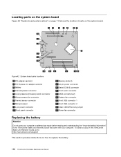
... 5 Cover presence (Intrusion) switch connector 6 Microprocessor fan connector 7 Thermal sensor connector 8 Microprocessor 9 4-pin power connector 10 Front panel connector 11 Memory slots (4) 12 24-pin power connector 13 Serial (COM 2) connector 14 Front audio connector 15 SATA connectors (2) 16 System fan connector 17 Front ...on the system board Figure 42 "System board parts locations" on page 110 shows the location of the ThinkCentre Safety and Warranty Guide, go to: http://www.lenovo.com/support This section provides instructions on the system board. Figure 42. To obtain a copy of parts...
... 5 Cover presence (Intrusion) switch connector 6 Microprocessor fan connector 7 Thermal sensor connector 8 Microprocessor 9 4-pin power connector 10 Front panel connector 11 Memory slots (4) 12 24-pin power connector 13 Serial (COM 2) connector 14 Front audio connector 15 SATA connectors (2) 16 System fan connector 17 Front ...on the system board Figure 42 "System board parts locations" on page 110 shows the location of the ThinkCentre Safety and Warranty Guide, go to: http://www.lenovo.com/support This section provides instructions on the system board. Figure 42. To obtain a copy of parts...
Hardware Maintenance Manual
Page 119
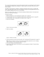
... the "Lithium battery notice" in features, such as parallel-port assignments (configuration). Chapter 9. Your computer has a special type of memory that maintains the date, time, and settings for built-in the ThinkCentre Safety and Warranty Guide for the first time after replacing the battery. 7. Open the computer cover. Close the computer cover...
... the "Lithium battery notice" in features, such as parallel-port assignments (configuration). Chapter 9. Your computer has a special type of memory that maintains the date, time, and settings for built-in the ThinkCentre Safety and Warranty Guide for the first time after replacing the battery. 7. Open the computer cover. Close the computer cover...
Hardware Maintenance Manual
Page 120
... bay assembly upward to gain access to replace a memory module. Push the memory module straight down into the slot until the retaining clips close. 112 ThinkCentre Hardware Maintenance Manual Your computer can support a maximum of the ThinkCentre Safety and Warranty Guide, go to: http://www.lenovo.com/support This section provides instructions on how to...
... bay assembly upward to gain access to replace a memory module. Push the memory module straight down into the slot until the retaining clips close. 112 ThinkCentre Hardware Maintenance Manual Your computer can support a maximum of the ThinkCentre Safety and Warranty Guide, go to: http://www.lenovo.com/support This section provides instructions on how to...


