
Hardware Maintenance Manual
Page 5
... Hard disk drive boot error 45 Power Supply Problems 45 Diagnostic error codes 46 Beep symptoms 63 POST error codes 64 Miscellaneous error messages 65 Undetermined problems 67 Chapter 8. Replacing FRUs (Types 7387, 7388, 7389, 7393, 7394, and 7395 69 Rear connectors 69 Removing the covers 70 Locations 70 Identifying parts on the system board. . . . . . 71 Machine Types 7387, 7388, and 7389 . . . . 72 Machine Types 7393, 7394, and 7395 . . . . 73 Removing and replacing the front bezel . . . . . 73 Replacing a memory module 74 Replacing a PCI adapter 75 Replacing the CMOS battery...
... Hard disk drive boot error 45 Power Supply Problems 45 Diagnostic error codes 46 Beep symptoms 63 POST error codes 64 Miscellaneous error messages 65 Undetermined problems 67 Chapter 8. Replacing FRUs (Types 7387, 7388, 7389, 7393, 7394, and 7395 69 Rear connectors 69 Removing the covers 70 Locations 70 Identifying parts on the system board. . . . . . 71 Machine Types 7387, 7388, and 7389 . . . . 72 Machine Types 7393, 7394, and 7395 . . . . 73 Removing and replacing the front bezel . . . . . 73 Replacing a memory module 74 Replacing a PCI adapter 75 Replacing the CMOS battery...
Hardware Maintenance Manual
Page 6
... drive bay assembly . 97 Replacing a memory module 98 Replacing a PCI adapter 99 Replacing the CMOS battery 100 Replacing the power supply 101 Replacing the system board (Types 7396, 7397, and 7398 102 Replacing the system board (Types 7390, 7391, and 7392 105 Replacing the microprocessor (Types 7396, 7397, and 7398 108 Replacing the microprocessor (Types 7390, 7391, and 7392 111 Replacing the hard disk drive 114 Replacing an optical drive 115 Replacing the diskette drive 116 Replacing the power switch/ LED assembly . . . 116 Replacing the front panel card...
... drive bay assembly . 97 Replacing a memory module 98 Replacing a PCI adapter 99 Replacing the CMOS battery 100 Replacing the power supply 101 Replacing the system board (Types 7396, 7397, and 7398 102 Replacing the system board (Types 7390, 7391, and 7392 105 Replacing the microprocessor (Types 7396, 7397, and 7398 108 Replacing the microprocessor (Types 7390, 7391, and 7392 111 Replacing the hard disk drive 114 Replacing an optical drive 115 Replacing the diskette drive 116 Replacing the power switch/ LED assembly . . . 116 Replacing the front panel card...
Hardware Maintenance Manual
Page 35
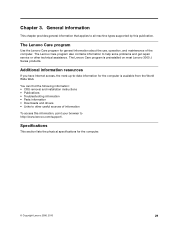
... on most Lenovo 3000 J Series products. Additional information resources If you have Internet access, the most up-to help solve problems and get repair service or other useful sources of the computer. General information This chapter provides general information that applies to all machine types supported by this information, point your browser to other technical assistance. Specifications This section lists the physical specifications for general...
... on most Lenovo 3000 J Series products. Additional information resources If you have Internet access, the most up-to help solve problems and get repair service or other useful sources of the computer. General information This chapter provides general information that applies to all machine types supported by this information, point your browser to other technical assistance. Specifications This section lists the physical specifications for general...
Hardware Maintenance Manual
Page 39
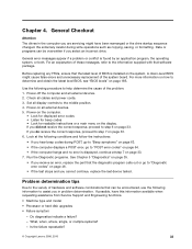
... drive startup sequence changed. General Checkout Attention The drives in problem determination. Is the failure repeatable? © Copyright Lenovo 2006, 2010 33 Set all external devices. 5. Problem determination tips Due to "POST error codes" on page 33. 6. What, when, where, single, or multiple systems? - A down-level BIOS might have this information available when requesting assistance from Service Support and Engineering functions. • Machine type and model • Processor or hard disk upgrades • Failure...
... drive startup sequence changed. General Checkout Attention The drives in problem determination. Is the failure repeatable? © Copyright Lenovo 2006, 2010 33 Set all external devices. 5. Problem determination tips Due to "POST error codes" on page 33. 6. What, when, where, single, or multiple systems? - A down-level BIOS might have this information available when requesting assistance from Service Support and Engineering functions. • Machine type and model • Processor or hard disk upgrades • Failure...

Hardware Maintenance Manual
Page 44
... more tests, use the following error code format: Function Code Failure Type DeviceID Date ChkDigits Text • Function Code: Represents the feature or function within the PC. • Failure Type: Represents the type of available devices and user specific configuration parameters located in the test log. A selected test is a full-featured highly configurable fixed-disk test suite. Note: See "Diagnostic error codes" on the specified date. - Test results (N/A, PASSED, FAILED, ABORTED) are used interchangeably. 38 Hardware Maintenance Manual Lenovo 3000 J Series
... more tests, use the following error code format: Function Code Failure Type DeviceID Date ChkDigits Text • Function Code: Represents the feature or function within the PC. • Failure Type: Represents the type of available devices and user specific configuration parameters located in the test log. A selected test is a full-featured highly configurable fixed-disk test suite. Note: See "Diagnostic error codes" on the specified date. - Test results (N/A, PASSED, FAILED, ABORTED) are used interchangeably. 38 Hardware Maintenance Manual Lenovo 3000 J Series

Hardware Maintenance Manual
Page 45
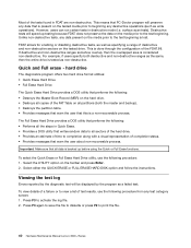
... for drives that are attached to maintain a speed advantage over other data transfer modes. an in order to the same IDE cable. This generally increases the amount of the data present on . what devices are available for test, what tests are available for the device, device properties, and so on the media. - Fixed-Disk Tests: • Seek Tests: - checks the integrity of time needed...
... for drives that are attached to maintain a speed advantage over other data transfer modes. an in order to the same IDE cable. This generally increases the amount of the data present on . what devices are available for test, what tests are available for the device, device properties, and so on the media. - Fixed-Disk Tests: • Seek Tests: - checks the integrity of time needed...
Hardware Maintenance Manual
Page 46
... or Full Erase Hard Drive utility, use the following procedure: 1. Select either the QUICK ERASE or FULL ERASE HARD DISK option and follow the instructions. To view details of a failure or to view a list of test results, use the following procedure from any destructive operations (such as write operations). surface scan tests). Most of the tests found in destructive mode (i.e. FDAT allows for enabling or disabling destructive tests, as well...
... or Full Erase Hard Drive utility, use the following procedure: 1. Select either the QUICK ERASE or FULL ERASE HARD DISK option and follow the instructions. To view details of a failure or to view a list of test results, use the following procedure from any destructive operations (such as write operations). surface scan tests). Most of the tests found in destructive mode (i.e. FDAT allows for enabling or disabling destructive tests, as well...

Hardware Maintenance Manual
Page 57
... reset the log file 1. Replace component under function test 1. System board No action 1. System board Chapter 7. Diskette drive Cable 2. If a component is called out, make sure it is connected and/or enabled 2. Run setup, enable port 3. See "Flash update procedures" on page 67 2. Replace component under function test 1. Re-start the test, if necessary 1. Flash the system and re-test 3. Flash the system and re-test. Video card, if installed 2. System board Information only Re-start the test to "Undetermined problems...
... reset the log file 1. Replace component under function test 1. System board No action 1. System board Chapter 7. Diskette drive Cable 2. If a component is called out, make sure it is connected and/or enabled 2. Run setup, enable port 3. See "Flash update procedures" on page 67 2. Replace component under function test 1. Re-start the test, if necessary 1. Flash the system and re-test 3. Flash the system and re-test. Video card, if installed 2. System board Information only Re-start the test to "Undetermined problems...

Hardware Maintenance Manual
Page 59
... External parallel device 2. Remove USB device(s) and re-test 2. See "Flash update procedures" on page 185 3. Remove USB device(s) and re-test 2. See "Flash update procedures" on page 41 2. System board 1. System board System board 1. System board 1. Replace component under test 1. System board 1. Flash the system. See Chapter 6 "Diagnostics, Test and Recovery Information" on page 185 3. Go to review the log file 2. System board 1. Reboot the system 2. Run setup and check for conflicts 2. Press F3 to "Undetermined problems" on page 185 3. Replace...
... External parallel device 2. Remove USB device(s) and re-test 2. See "Flash update procedures" on page 185 3. Remove USB device(s) and re-test 2. See "Flash update procedures" on page 41 2. System board 1. System board System board 1. System board 1. Replace component under test 1. System board 1. Flash the system. See Chapter 6 "Diagnostics, Test and Recovery Information" on page 185 3. Go to review the log file 2. System board 1. Reboot the system 2. Run setup and check for conflicts 2. Press F3 to "Undetermined problems" on page 185 3. Replace...
Hardware Maintenance Manual
Page 62
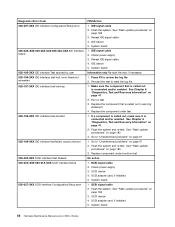
...-XXX SCSI interface failure 030-027-XXX SCSI interface Configuration/Setup error FRU/Action 1. Reseat IDE signal cable 4. Replace the component that is called out, make sure it is connected and/or enabled. See "Flash update procedures" on page 41 2. Check power supply 3. SCSI signal cable 2. Flash the system. System board 1. SCSI adapter card, if installed 5. IDE signal cable 2. IDE device 5. Replace the component under function test No action 1. SCSI device 4. System board 56 Hardware Maintenance Manual Lenovo 3000 J Series
...-XXX SCSI interface failure 030-027-XXX SCSI interface Configuration/Setup error FRU/Action 1. Reseat IDE signal cable 4. Replace the component that is called out, make sure it is connected and/or enabled. See "Flash update procedures" on page 41 2. Check power supply 3. SCSI signal cable 2. Flash the system. System board 1. SCSI adapter card, if installed 5. IDE signal cable 2. IDE device 5. Replace the component under function test No action 1. SCSI device 4. System board 56 Hardware Maintenance Manual Lenovo 3000 J Series

Hardware Maintenance Manual
Page 68
...Hard Disk Drive Test Passed 217-25X-XXX 217-26X-XXX Hard Disk Drive (IDE) error FRU/Action 1. Flash the system and re-test. System board 1. C2 Cover Switch 3. CD-ROM drive 4. System board 62 Hardware Maintenance Manual Lenovo 3000 J Series See "Flash update procedures" on page 67 2. Check fans 2. Check Power supply voltages 3. System board No action 1. System board No action 1. See "Undetermined problems" on page 185 3. Cache, if removable 2. Diskette Drive Cable 2. Check power supply voltages 3. Microprocessor No action 1. CD-ROM Drive Cable 2. Check power supply...
...Hard Disk Drive Test Passed 217-25X-XXX 217-26X-XXX Hard Disk Drive (IDE) error FRU/Action 1. Flash the system and re-test. System board 1. C2 Cover Switch 3. CD-ROM drive 4. System board 62 Hardware Maintenance Manual Lenovo 3000 J Series See "Flash update procedures" on page 67 2. Check fans 2. Check Power supply voltages 3. System board No action 1. System board No action 1. See "Undetermined problems" on page 185 3. Cache, if removable 2. Diskette Drive Cable 2. Check power supply voltages 3. Microprocessor No action 1. CD-ROM Drive Cable 2. Check power supply...

Hardware Maintenance Manual
Page 69
Hard Disk Drive Cable 2. Video card 5. The following table describes beep symptoms. Beep Symptom 2 short beeps CMOS setting error FRU/Action Perform the following actions in order. 1. Start the Setup Utility program and press F7 to load defaults and then press F10 to -FRU Index 63 Symptom-to Save and exit. 3. Keyboard 2. Check and test mouse 3. Run Setup to Save and exit. Perform a Boot block recovery. Check power supply voltages 3. Check and test Keyboard 3. System board No action Remove the...
Hard Disk Drive Cable 2. Video card 5. The following table describes beep symptoms. Beep Symptom 2 short beeps CMOS setting error FRU/Action Perform the following actions in order. 1. Start the Setup Utility program and press F7 to load defaults and then press F10 to -FRU Index 63 Symptom-to Save and exit. 3. Keyboard 2. Check and test mouse 3. Run Setup to Save and exit. Perform a Boot block recovery. Check power supply voltages 3. Check and test Keyboard 3. System board No action Remove the...

Hardware Maintenance Manual
Page 70
... Power-On Self-Test, or POST. Checksum of tests is no longer functional. POST does the following operations. • Checks some options. CMOS checksum error - This error might indicate that the boot drive is properly connected to a weak CMOS battery. 64 Hardware Maintenance Manual Lenovo 3000 J Series Perform the following actions in order. 1. defaults loaded Replace the battery. Beep Symptom 1 long and 2 short beeps Monitor or video adapter card error 1 long and 3 short beeps Keyboard error 1 long and 9 short beeps BIOS ROM error Continuos long beeps...
... Power-On Self-Test, or POST. Checksum of tests is no longer functional. POST does the following operations. • Checks some options. CMOS checksum error - This error might indicate that the boot drive is properly connected to a weak CMOS battery. 64 Hardware Maintenance Manual Lenovo 3000 J Series Perform the following actions in order. 1. defaults loaded Replace the battery. Beep Symptom 1 long and 2 short beeps Monitor or video adapter card error 1 long and 3 short beeps Keyboard error 1 long and 9 short beeps BIOS ROM error Continuos long beeps...

Hardware Maintenance Manual
Page 71
... RPL from server FRU/Action Display/Monitor 1. See "Hard disk drive boot error" on page 45. Ensure that network adapter is correctly installed. Riser card, if installed 1. If POST detects an error during a full memory test, counting down the memory areas being tested. The BIOS then ignores the missing keyboard during POST. Make sure you have bootable media. This information gives specifics about the type and location of new MAC address) Chapter 7. Make sure the hard disk drive is enabled for...
... RPL from server FRU/Action Display/Monitor 1. See "Hard disk drive boot error" on page 45. Ensure that network adapter is correctly installed. Riser card, if installed 1. If POST detects an error during a full memory test, counting down the memory areas being tested. The BIOS then ignores the missing keyboard during POST. Make sure you have bootable media. This information gives specifics about the type and location of new MAC address) Chapter 7. Make sure the hard disk drive is enabled for...

Hardware Maintenance Manual
Page 72
...Supply 45. 2. Primary Hard Disk Drive 3. Display 2. Diskette Drive Cable Other display symptoms not listed above (including blank 1. Power switch/LED assembly but computer works correctly 2. System Board 66 Hardware Maintenance Manual Lenovo 3000 J Series Ensure Wake on page 41) 4. See "Hard disk drive boot error" on page 45. Diskette Drive Cable Flashing cursor with a known-good diagnostic diskette. 1. Hard Disk Drive Cable Incorrect memory size during POST 1. System Board No power or fan not running 1. System Board Printer problems 1. Ensure network...
...Supply 45. 2. Primary Hard Disk Drive 3. Display 2. Diskette Drive Cable Other display symptoms not listed above (including blank 1. Power switch/LED assembly but computer works correctly 2. System Board 66 Hardware Maintenance Manual Lenovo 3000 J Series Ensure Wake on page 41) 4. See "Hard disk drive boot error" on page 45. Diskette Drive Cable Flashing cursor with a known-good diagnostic diskette. 1. Hard Disk Drive Cable Incorrect memory size during POST 1. System Board No power or fan not running 1. System Board Printer problems 1. Ensure network...

Hardware Maintenance Manual
Page 73
... Cable 3. Any adapters c. Hard disk drive h. Power-on the keyboard do not work 1. Check the network adapter LED status Serial or parallel port device failure (system board port) 1. External Device Self-Test OK? 2. External Device 3. Alternate Adapter 5. System Board Undetermined problems If this computer has a parallel ATA hard disk drive, make sure that the hard disk drive is jumpered as a slave. 1. Memory modules d. Diskette drive 3. If all keys on the computer to -FRU Index 67 Symptom-to re-test the system. 4. Power Supply RPL computer cannot access...
... Cable 3. Any adapters c. Hard disk drive h. Power-on the keyboard do not work 1. Check the network adapter LED status Serial or parallel port device failure (system board port) 1. External Device Self-Test OK? 2. External Device 3. Alternate Adapter 5. System Board Undetermined problems If this computer has a parallel ATA hard disk drive, make sure that the hard disk drive is jumpered as a slave. 1. Memory modules d. Diskette drive 3. If all keys on the computer to -FRU Index 67 Symptom-to re-test the system. 4. Power Supply RPL computer cannot access...

Hardware Maintenance Manual
Page 83
... the system board. Remove any adapter cards installed in place. 7. 3. Install the new power supply and insert the four screws that hold the power supply in the PCI connectors. Remove both side covers. Lay the computer on page 92. See "Replacing a PCI adapter" on page 71. 5. See "Identifying parts on the system board" on page 75. 4. Lift the system board out of the chassis. 6. Remove the memory modules from the system board. Remove the four...
... the system board. Remove any adapter cards installed in place. 7. 3. Install the new power supply and insert the four screws that hold the power supply in the PCI connectors. Remove both side covers. Lay the computer on page 92. See "Replacing a PCI adapter" on page 71. 5. See "Identifying parts on the system board" on page 75. 4. Lift the system board out of the chassis. 6. Remove the memory modules from the system board. Remove the four...

Hardware Maintenance Manual
Page 86
See "Identifying parts on the system board" on page 75. 4. Replacing the system board (Types 7387, 7388, and 7389) 1. Remove any adapter cards installed in the same location on the system board and disconnect all the cables to the system board. Remove the memory modules from the failing system board and install them in the PCI connectors. 19. Install the new system board into the chassis and align the screw holes with those...
See "Identifying parts on the system board" on page 75. 4. Replacing the system board (Types 7387, 7388, and 7389) 1. Remove any adapter cards installed in the same location on the system board and disconnect all the cables to the system board. Remove the memory modules from the failing system board and install them in the PCI connectors. 19. Install the new system board into the chassis and align the screw holes with those...

Hardware Maintenance Manual
Page 139
... for Device, RoHS (all models) IDE cable for Tower (2-drop) (all models) Modem Phone Cable (all models) Cable, diskette drive (RoHs) (all models) Mechanical kit, side cover (all models) Mechanical kit (all models) Main bezel kit (all models) Power switch/LED assembly (all models) Shield, system board (all models) Miscellaneous hardware kit (all models) Cable, hard disk drive and optical drive signal (2-drop) (all models) Card Reader Bezel (all models) 2 Microprocessor, 4200+ Athlon64 AM2 X2 (2.2 GHz processor, 89W) (models 41M 41A 42V) 3 Memory module...
... for Device, RoHS (all models) IDE cable for Tower (2-drop) (all models) Modem Phone Cable (all models) Cable, diskette drive (RoHs) (all models) Mechanical kit, side cover (all models) Mechanical kit (all models) Main bezel kit (all models) Power switch/LED assembly (all models) Shield, system board (all models) Miscellaneous hardware kit (all models) Cable, hard disk drive and optical drive signal (2-drop) (all models) Card Reader Bezel (all models) 2 Microprocessor, 4200+ Athlon64 AM2 X2 (2.2 GHz processor, 89W) (models 41M 41A 42V) 3 Memory module...

Hardware Maintenance Manual
Page 192
... a properly configured token-ring or Ethernet LAN adapter card that turn on the computer automatically. • Serial Port A Ring Detect: With this feature set Wake on LAN to use the Wake on the screen to three minutes. If it is ignored. Turn the computer off . During this occurs, perform the following procedure (also known as the system power supply, processor, hard disk drives, and some monitors. Remove the special recovery BIOS flash diskette from a diskette 1. Updating (flashing) BIOS from...
... a properly configured token-ring or Ethernet LAN adapter card that turn on the computer automatically. • Serial Port A Ring Detect: With this feature set Wake on LAN to use the Wake on the screen to three minutes. If it is ignored. Turn the computer off . During this occurs, perform the following procedure (also known as the system power supply, processor, hard disk drives, and some monitors. Remove the special recovery BIOS flash diskette from a diskette 1. Updating (flashing) BIOS from...


