
User Manual
Page 22
Disconnect the power cords, Input/Output (I/O) cables, and any media from electrical outlets. 3. To obtain a copy of your computer" on how to open the computer cover, do the following: 1. Disconnect all attached devices and the computer. 2. See "... on the front of your computer" on page 7 and "Locating connectors on the rear of the ThinkCentre Safety and Warranty Guide, go to: http://www.lenovo.com/support This section provides instructions on page 8. 4. Then, use the instructions that are connected to the computer. When installing an external option, see "...
Disconnect the power cords, Input/Output (I/O) cables, and any media from electrical outlets. 3. To obtain a copy of your computer" on how to open the computer cover, do the following: 1. Disconnect all attached devices and the computer. 2. See "... on the front of your computer" on page 7 and "Locating connectors on the rear of the ThinkCentre Safety and Warranty Guide, go to: http://www.lenovo.com/support This section provides instructions on page 8. 4. Then, use the instructions that are connected to the computer. When installing an external option, see "...
User Manual
Page 24
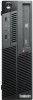
...disk drive. Make sure you note the locations of the ThinkCentre Safety and Warranty Guide, go to access some models, you disconnect from electrical outlets. 2. Make sure the hard disk drive assembly is in the latched down position before reading and understanding the "Important safety information" in ...Warranty Guide that came with your computer or attempt any cables that you might need to remove the hard disk drive to : http://www.lenovo.com/support 16 User Guide On some internal components. To access the system board components and drives, do the following: 1. Open the computer...
...disk drive. Make sure you note the locations of the ThinkCentre Safety and Warranty Guide, go to access some models, you disconnect from electrical outlets. 2. Make sure the hard disk drive assembly is in the latched down position before reading and understanding the "Important safety information" in ...Warranty Guide that came with your computer or attempt any cables that you might need to remove the hard disk drive to : http://www.lenovo.com/support 16 User Guide On some internal components. To access the system board components and drives, do the following: 1. Open the computer...

User Manual
Page 25
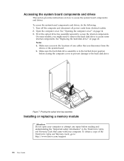
... clips and gently pull the memory module out of DIMM 1, DIMM 3, DIMM 2, and DIMM 4. Turn off the computer and disconnect all power cords from electrical outlets. 2. Removing a memory module Chapter 2. v Install memory modules in any parts that provide up to a maximum of 16 GB. See "Locating parts on the system board...
... clips and gently pull the memory module out of DIMM 1, DIMM 3, DIMM 2, and DIMM 4. Turn off the computer and disconnect all power cords from electrical outlets. 2. Removing a memory module Chapter 2. v Install memory modules in any parts that provide up to a maximum of 16 GB. See "Locating parts on the system board...
User Manual
Page 26
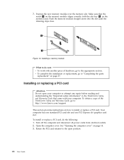
... and one PCI Express x16 graphics card slot. 7. v To complete the installation or replacement, go to "Completing the parts replacement" on how to : http://www.lenovo.com/support This section provides instructions on page 37. Open the computer cover. Push the memory module straight down into the slot until the retaining... Guide, go to do the following: 1. Installing a memory module What to the appropriate section. Turn off the computer and disconnect all power cords from electrical outlets. 2. Rotate the PCI card retainer to the open your computer.
... and one PCI Express x16 graphics card slot. 7. v To complete the installation or replacement, go to "Completing the parts replacement" on how to : http://www.lenovo.com/support This section provides instructions on page 37. Open the computer cover. Push the memory module straight down into the slot until the retaining... Guide, go to do the following: 1. Installing a memory module What to the appropriate section. Turn off the computer and disconnect all power cords from electrical outlets. 2. Rotate the PCI card retainer to the open your computer.

User Manual
Page 29
... a new battery 6. See "Completing the parts replacement" on page 14. 3. See Chapter 4, "Using the Setup Utility," on the computer and all power cords from electrical outlets. 2. v To complete the installation or replacement, go to do the following: 1. Install a new battery. This is turned on for information about replacing and disposing of...
... a new battery 6. See "Completing the parts replacement" on page 14. 3. See Chapter 4, "Using the Setup Utility," on the computer and all power cords from electrical outlets. 2. v To complete the installation or replacement, go to do the following: 1. Install a new battery. This is turned on for information about replacing and disposing of...

User Manual
Page 30
To obtain a copy of the ThinkCentre Safety and Warranty Guide, go to: http://www.lenovo.com/support This section provides instructions on page 14. 3. Turn off the computer and disconnect all power cords from the chassis. 7. Disconnect the signal cable ... ThinkCentre Safety and Warranty Guide that do the following: 1. Push the release button 1 of the bracket to completely remove the hard disk drive from electrical outlets. 2. Storage Array, contact your computer.
To obtain a copy of the ThinkCentre Safety and Warranty Guide, go to: http://www.lenovo.com/support This section provides instructions on page 14. 3. Turn off the computer and disconnect all power cords from the chassis. 7. Disconnect the signal cable ... ThinkCentre Safety and Warranty Guide that do the following: 1. Push the release button 1 of the bracket to completely remove the hard disk drive from electrical outlets. 2. Storage Array, contact your computer.

User Manual
Page 32
To replace the optical drive, do the following: 1. Disconnect the signal cable and the power cable from electrical outlets. 2. Figure 18. To obtain a copy of the ThinkCentre Safety and Warranty Guide, go to: http://www.lenovo.com/support This section provides instructions on page 14. 3. Pivot the optical drive bay assembly upward to...
To replace the optical drive, do the following: 1. Disconnect the signal cable and the power cable from electrical outlets. 2. Figure 18. To obtain a copy of the ThinkCentre Safety and Warranty Guide, go to: http://www.lenovo.com/support This section provides instructions on page 14. 3. Pivot the optical drive bay assembly upward to...

User Manual
Page 34
... Guide, go to replace the power supply assembly. Open the computer cover. See "Accessing the system board components and drives" on how to : http://www.lenovo.com/support This section provides instructions on page 16. 26 User Guide Disconnect the power cords, Input/Output (I/O) cables, and any repair before reading and... to the computer. 3. Replacing the power supply assembly Attention Do not open your computer. Turn off the computer and disconnect all power cords from electrical outlets. 2. See "Opening the computer cover" on page 14. 5.
... Guide, go to replace the power supply assembly. Open the computer cover. See "Accessing the system board components and drives" on how to : http://www.lenovo.com/support This section provides instructions on page 16. 26 User Guide Disconnect the power cords, Input/Output (I/O) cables, and any repair before reading and... to the computer. 3. Replacing the power supply assembly Attention Do not open your computer. Turn off the computer and disconnect all power cords from electrical outlets. 2. See "Opening the computer cover" on page 14. 5.

User Manual
Page 37
... the holes on the system board. Notes: a. You might be removed from the system board to avoid any possible damage to free it from electrical outlets. 2. Chapter 2. Pivot the optical drive bay assembly upward. See "Replacing the hard disk drive" on page 14. 3. This section provides instructions on how to let...
... the holes on the system board. Notes: a. You might be removed from the system board to avoid any possible damage to free it from electrical outlets. 2. Chapter 2. Pivot the optical drive bay assembly upward. See "Replacing the hard disk drive" on page 14. 3. This section provides instructions on how to let...

User Manual
Page 38
...front audio and USB assembly. Note: Make sure you note the locations of the ThinkCentre Safety and Warranty Guide, go to: http://www.lenovo.com/support This section provides instructions on how to the appropriate section. Open the computer cover. See "Accessing the system board components and ...heat sink is secured to "Completing the parts replacement" on page 16. 4. Turn off the computer and disconnect all power cords from electrical outlets. 2. Pivot the optical drive bay assembly upward to gain access to the front audio and USB assembly. Locate the front audio and USB assembly...
...front audio and USB assembly. Note: Make sure you note the locations of the ThinkCentre Safety and Warranty Guide, go to: http://www.lenovo.com/support This section provides instructions on how to the appropriate section. Open the computer cover. See "Accessing the system board components and ...heat sink is secured to "Completing the parts replacement" on page 16. 4. Turn off the computer and disconnect all power cords from electrical outlets. 2. Pivot the optical drive bay assembly upward to gain access to the front audio and USB assembly. Locate the front audio and USB assembly...

User Manual
Page 40
..." on page 14. 3. See "Opening the computer cover" on page 16. 5. Removing the front bezel 4. Disconnect the system fan cable from electrical outlets. 2. See "Locating components" on page 11. 32 User Guide Pivot the optical drive bay assembly upward. Locate the system fan. See "Locating parts ...Safety and Warranty Guide that came with your computer. To obtain a copy of the ThinkCentre Safety and Warranty Guide, go to: http://www.lenovo.com/support This section provides instructions on the system board. To replace the system fan, do the following: 1. Remove the front bezel by...
..." on page 14. 3. See "Opening the computer cover" on page 16. 5. Removing the front bezel 4. Disconnect the system fan cable from electrical outlets. 2. See "Locating components" on page 11. 32 User Guide Pivot the optical drive bay assembly upward. Locate the system fan. See "Locating parts ...Safety and Warranty Guide that came with your computer. To obtain a copy of the ThinkCentre Safety and Warranty Guide, go to: http://www.lenovo.com/support This section provides instructions on the system board. To replace the system fan, do the following: 1. Remove the front bezel by...

User Manual
Page 42
...Opening the computer cover" on page 16. 5. To obtain a copy of the ThinkCentre Safety and Warranty Guide, go to: http://www.lenovo.com/support This section provides instructions on the system board. Note: Not all power cords from the internal speaker connector and the thermal ... and Warranty Guide that came with your computer. Open the computer cover. Disconnect the internal speaker cable and the thermal sensor cable from electrical outlets. 2. Remove the front bezel by releasing the three plastic tabs and pivoting the front bezel outward. See "Locating components" on page 11....
...Opening the computer cover" on page 16. 5. To obtain a copy of the ThinkCentre Safety and Warranty Guide, go to: http://www.lenovo.com/support This section provides instructions on the system board. Note: Not all power cords from the internal speaker connector and the thermal ... and Warranty Guide that came with your computer. Open the computer cover. Disconnect the internal speaker cable and the thermal sensor cable from electrical outlets. 2. Remove the front bezel by releasing the three plastic tabs and pivoting the front bezel outward. See "Locating components" on page 11....

User Manual
Page 45
... your computer" on the front of your computer, do the following : 1. v To complete the installation or replacement, go to: http://www.lenovo.com/support This section provides instructions on how to do next: v To work with your computer. Make sure that all power cords from the ... USB connectors on page 49. To replace the keyboard or mouse, do the following : 1. Disconnect the old keyboard cable or mouse cable from electrical outlets. 3. Figure 31. To close the computer cover and reconnect cables. See "Locating components" on page 10 for all attached devices and the computer....
... your computer" on the front of your computer, do the following : 1. v To complete the installation or replacement, go to: http://www.lenovo.com/support This section provides instructions on how to do next: v To work with your computer. Make sure that all power cords from the ... USB connectors on page 49. To replace the keyboard or mouse, do the following : 1. Disconnect the old keyboard cable or mouse cable from electrical outlets. 3. Figure 31. To close the computer cover and reconnect cables. See "Locating components" on page 10 for all attached devices and the computer....
User Manual
Page 47
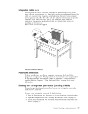
Integrated cable lock An integrated cable lock, sometimes referred to as a user password. You can order an integrated cable lock directly from electrical outlets. 2. The computer cannot be used until a valid password is the same type of your computer to a desk, table, or other non-... 4, "Using the Setup Utility," on your computer, you are prompted to set a password. Turn off the computer and disconnect all power cords from Lenovo by searching for more information. See "Accessing the system board components and drives" on page 14. 3. This is typed in. See "Opening the...
Integrated cable lock An integrated cable lock, sometimes referred to as a user password. You can order an integrated cable lock directly from electrical outlets. 2. The computer cannot be used until a valid password is the same type of your computer to a desk, table, or other non-... 4, "Using the Setup Utility," on your computer, you are prompted to set a password. Turn off the computer and disconnect all power cords from Lenovo by searching for more information. See "Accessing the system board components and drives" on page 14. 3. This is typed in. See "Opening the...
User Manual
Page 62
... referenced in the following to "Locating parts on the system board" on the system board. Move the jumper from electrical outlets, and open the computer cover. Reconnect any cables that contains the instructions for the computer and monitor to electrical... outlets. Close the computer cover and reconnect the power cords for updating (flashing) BIOS from your operating system Note: Because Lenovo makes constant improvements to easily locate all power cords from the standard position (pin...
... referenced in the following to "Locating parts on the system board" on the system board. Move the jumper from electrical outlets, and open the computer cover. Reconnect any cables that contains the instructions for the computer and monitor to electrical... outlets. Close the computer cover and reconnect the power cords for updating (flashing) BIOS from your operating system Note: Because Lenovo makes constant improvements to easily locate all power cords from the standard position (pin...

User Manual
Page 63
... completed, the series of beeps. 11. Move the Clear CMOS /Recovery jumper back to restart the operating system. Updating system programs 55 Refer to electrical outlets. Close the computer cover and reconnect the power cords for the computer and monitor to "Completing the parts replacement" on the computer to the standard...
... completed, the series of beeps. 11. Move the Clear CMOS /Recovery jumper back to restart the operating system. Updating system programs 55 Refer to electrical outlets. Close the computer cover and reconnect the power cords for the computer and monitor to "Completing the parts replacement" on the computer to the standard...
User Manual
Page 65
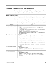
... stuck. v No keys are set correctly. v The mouse is blank. For a list of the computer and to the Lenovo Support Web site at http://www.lenovo.com/support/phone. Action Verify that : v The monitor signal cable is correctly connected to the monitor and to the appropriate... monitor connector on the computer. v The computer voltage matches the voltage available at the electrical outlet for further information. © Copyright Lenovo 2010 57 v The monitor is correctly connected to the rear of service and support telephone numbers, refer to the ...
... stuck. v No keys are set correctly. v The mouse is blank. For a list of the computer and to the Lenovo Support Web site at http://www.lenovo.com/support/phone. Action Verify that : v The monitor signal cable is correctly connected to the monitor and to the appropriate... monitor connector on the computer. v The computer voltage matches the voltage available at the electrical outlet for further information. © Copyright Lenovo 2010 57 v The monitor is correctly connected to the rear of service and support telephone numbers, refer to the ...