
UDS-10 - Product Brief
Page 2
... of their respective owners. All other trademarks are the property of Lantronix, Inc. Specifications subject to change without parity requiring Ethernet access Network Interface RJ45 (10Base-T) Ethernet (UDS-10) RJ45 (10Base-T/100Base-TX) Ethernet (UDS 100) Serial Interface DB25F, RS-232/RS-422/RS-485 serial...Irvine | CA 92618 | USA | Tel: 800.422.7055 | Fax: 949.450.7232 | www.lantronix.com ©2006 Lantronix, Inc. All rights reserved. 910-316 07/06 DGS2500 Device Server™ UDS-10/UDS100 Features Protocols Supported ARP, UDP, TCP, Telnet, ICMP, SNMP, DHCP, TFTP, and HTTP Device...
... of their respective owners. All other trademarks are the property of Lantronix, Inc. Specifications subject to change without parity requiring Ethernet access Network Interface RJ45 (10Base-T) Ethernet (UDS-10) RJ45 (10Base-T/100Base-TX) Ethernet (UDS 100) Serial Interface DB25F, RS-232/RS-422/RS-485 serial...Irvine | CA 92618 | USA | Tel: 800.422.7055 | Fax: 949.450.7232 | www.lantronix.com ©2006 Lantronix, Inc. All rights reserved. 910-316 07/06 DGS2500 Device Server™ UDS-10/UDS100 Features Protocols Supported ARP, UDP, TCP, Telnet, ICMP, SNMP, DHCP, TFTP, and HTTP Device...
UDS-10 / UDS100 / UDS200 - Quick Start Guide
Page 3
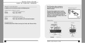
...and troubleshoot your unit using a network connection and our DeviceInstaller software. Ethernet, Power, and Serial Connections PINOUTS UDS-10 UDS100 UDS200 2 WWW.LANTRONIX.COM 3 The UDS products allow serial devices to the UDS, the box contains the following items: POWER SUPPLY (DOMESTIC UNITS) PART # COMPONENT DESCRIPTION 520-006 Power... international adapters DOCUMENTATION: CD-ROM and Quick Start Guide containing User Guides and software utilities. Quick Start Guide UDS-10, UDS100, UDS200 WHAT'S IN THE BOX In addition to connect and communicate over an Ethernet network.
...and troubleshoot your unit using a network connection and our DeviceInstaller software. Ethernet, Power, and Serial Connections PINOUTS UDS-10 UDS100 UDS200 2 WWW.LANTRONIX.COM 3 The UDS products allow serial devices to the UDS, the box contains the following items: POWER SUPPLY (DOMESTIC UNITS) PART # COMPONENT DESCRIPTION 520-006 Power... international adapters DOCUMENTATION: CD-ROM and Quick Start Guide containing User Guides and software utilities. Quick Start Guide UDS-10, UDS100, UDS200 WHAT'S IN THE BOX In addition to connect and communicate over an Ethernet network.
UDS-10 / UDS100 / UDS200 - Quick Start Guide
Page 4
The UDS looks for the IP your PC. Confirm that one of the Link LEDs lights up . b) Enter your CD-ROM drive. Insert the CD into your CD drive letter, colon, backslash, device_installer, backslash, DeviceInstaller.exe (e.g., E:\device_installer\.DeviceInstaller.exe). 2. WWW.LANTRONIX.COM ...IP address called DHCP. The systems administrator generally provides the IP address. Respond to 30 VDC, 2W maximum). 3. Quick Start Guide UDS-10, UDS100, UDS200 IP ADDRESSING Your unit must have a unique IP address on continuously. IP Address: Subnet Mask: Gateway: 4 ...
The UDS looks for the IP your PC. Confirm that one of the Link LEDs lights up . b) Enter your CD-ROM drive. Insert the CD into your CD drive letter, colon, backslash, device_installer, backslash, DeviceInstaller.exe (e.g., E:\device_installer\.DeviceInstaller.exe). 2. WWW.LANTRONIX.COM ...IP address called DHCP. The systems administrator generally provides the IP address. Respond to 30 VDC, 2W maximum). 3. Quick Start Guide UDS-10, UDS100, UDS200 IP ADDRESSING Your unit must have a unique IP address on continuously. IP Address: Subnet Mask: Gateway: 4 ...

UDS-10 / UDS100 / UDS200 - Quick Start Guide
Page 5
... the IP icon . Quick Start Guide UDS-10, UDS100, UDS200 ASSIGN IP ADDRESS AND NETWORK CLASS 1. Input the IP address, Subnet mask, and Gateway being assigned to enable BOOTP, DHCP or Auto IP on the Task Bar and select Programs ➜ Lantronix ➜ DeviceInstaller DeviceInstaller. Click Next. WWW.LANTRONIX.COM 7 Enter the Hardware or...
... the IP icon . Quick Start Guide UDS-10, UDS100, UDS200 ASSIGN IP ADDRESS AND NETWORK CLASS 1. Input the IP address, Subnet mask, and Gateway being assigned to enable BOOTP, DHCP or Auto IP on the Task Bar and select Programs ➜ Lantronix ➜ DeviceInstaller DeviceInstaller. Click Next. WWW.LANTRONIX.COM 7 Enter the Hardware or...

UDS-10 / UDS100 / UDS200 - Quick Start Guide
Page 6
Click the Assign button to open the UDS web configuration pages. Figure 5. Assign IP Address Window CONFIGURATION Once the UDS is in the device list it can be configured via telnet. Note: For details about configuration settings, see the UDS User Guide. 8 WWW.LANTRONIX.COM 9 Quick Start Guide UDS-10, UDS100, UDS200 ASSIGN IP ADDRESS CON'T. 6. Use the Web button to finalize the IP assignment. Use the Telnet button to connect to the unit via several options.
Click the Assign button to open the UDS web configuration pages. Figure 5. Assign IP Address Window CONFIGURATION Once the UDS is in the device list it can be configured via telnet. Note: For details about configuration settings, see the UDS User Guide. 8 WWW.LANTRONIX.COM 9 Quick Start Guide UDS-10, UDS100, UDS200 ASSIGN IP ADDRESS CON'T. 6. Use the Web button to finalize the IP assignment. Use the Telnet button to connect to the unit via several options.

UDS-10 / UDS100 / UDS200 - Quick Start Guide
Page 7
...times the green LED blinks between its pauses. Quick Start Guide UDS-10, UDS100, UDS200 LEDS/TROUBLESHOOT The unit contains the following table explains the LED functions. If... the red LED is wrong. SERIAL LEDS 10 Mbps link/activity steady green 10 Mbps link/activity blinking 100 Mbps link/activity steady green 100 Mbps ...green Diagnostic blinking red and status blinking green Status steady green Status blinking green MEANING Valid 10 Mbps network connection Network packets transmitting and receiving Valid 100 Mbps network connection Network packets transmitting...
...times the green LED blinks between its pauses. Quick Start Guide UDS-10, UDS100, UDS200 LEDS/TROUBLESHOOT The unit contains the following table explains the LED functions. If... the red LED is wrong. SERIAL LEDS 10 Mbps link/activity steady green 10 Mbps link/activity blinking 100 Mbps link/activity steady green 100 Mbps ...green Diagnostic blinking red and status blinking green Status steady green Status blinking green MEANING Valid 10 Mbps network connection Network packets transmitting and receiving Valid 100 Mbps network connection Network packets transmitting...

UDS-10 / UDS100 / UDS200 - Quick Start Guide
Page 8
Lantronix 15353 Barranca Parkway Irvine, CA 92618, USA Phone: (949) 453-3990 Fax: (949) 453-3995 www.lantronix.com 12 Quick Start Guide UDS-10, UDS100, UDS200 CONTACT For questions and technical support, please check our online knowledge base at www.lantronix.com/support If you need additional help call us at: (800) 422-7044 Domestic (949) 453-7198 International (949) 450-7226 Fax Our phone lines are open from 6:00 AM - 5:30 PM Pacific Time Monday through Friday excluding holidays.
Lantronix 15353 Barranca Parkway Irvine, CA 92618, USA Phone: (949) 453-3990 Fax: (949) 453-3995 www.lantronix.com 12 Quick Start Guide UDS-10, UDS100, UDS200 CONTACT For questions and technical support, please check our online knowledge base at www.lantronix.com/support If you need additional help call us at: (800) 422-7044 Domestic (949) 453-7198 International (949) 450-7226 Fax Our phone lines are open from 6:00 AM - 5:30 PM Pacific Time Monday through Friday excluding holidays.

UDS-10 / UDS100 - User Guide
Page 6
Lantronix Web Manager 20 Figure 4-4. Network Configuration 24 Figure 5-4. Channel 1... Device and Network 14 Figure 4-1. Serial Interface 51 Figure 9-2. DB25 Female DCE Interface RS232 52 Figure 9-3. UDS Connected to Another Unit 41 Figure 6-3. Server Properties Configuration on the Web Browser 21 Figure 5-1. Network Login ...Mode Using the Network 43 Figure 9-1. UDS10/UDS100 User Guide Network Port 53 Ethernet Connector Pinouts 54 10: Technical Specifications 55 UDS10 Technical Specifications 55 UDS100 Technical Specifications 56 A: Alternative Ways to Assign an...
Lantronix Web Manager 20 Figure 4-4. Network Configuration 24 Figure 5-4. Channel 1... Device and Network 14 Figure 4-1. Serial Interface 51 Figure 9-2. DB25 Female DCE Interface RS232 52 Figure 9-3. UDS Connected to Another Unit 41 Figure 6-3. Server Properties Configuration on the Web Browser 21 Figure 5-1. Network Login ...Mode Using the Network 43 Figure 9-1. UDS10/UDS100 User Guide Network Port 53 Ethernet Connector Pinouts 54 10: Technical Specifications 55 UDS10 Technical Specifications 55 UDS100 Technical Specifications 56 A: Alternative Ways to Assign an...

UDS-10 / UDS100 - User Guide
Page 8
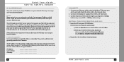
...common problems and error messages and how to contact Lantronix Technical Support. Lists technical specifications for installing and maintaining the UDS. Provides instructions on converting binary values to hexadecimals and tables listing all UDS configuration options in this guide include: 2: Introduction... Information 9: Connections and Pinouts 10: Technical Specifications A: Alternative Ways to Assign an IP Address B: Binary to configure settings for obtaining the latest firmware and updating the UDS. Provides descriptions and illustrations of the UDS and the protocols it up and...
...common problems and error messages and how to contact Lantronix Technical Support. Lists technical specifications for installing and maintaining the UDS. Provides instructions on converting binary values to hexadecimals and tables listing all UDS configuration options in this guide include: 2: Introduction... Information 9: Connections and Pinouts 10: Technical Specifications A: Alternative Ways to Assign an IP Address B: Binary to configure settings for obtaining the latest firmware and updating the UDS. Provides descriptions and illustrations of the UDS and the protocols it up and...
UDS-10 / UDS100 - User Guide
Page 29
... started with host 121.2.4.5, port 1 Connect to 129.1.2.5, port 1234 Connect to 129.1.28.10, port 12 Autostart (Automatic Connection): If you omit the port number from the serial port. ... address must be in the hostlist. 29 If the command string includes a partial IP address, the UDS interprets it connects to another IP in the command string. For example, C50.1/23 would connect to... in the range 1-65535, and must be in the hostlist table. If this option, the Lantronix unit scrolls through the table until it connects, the unit stops trying to connect to any others...
... started with host 121.2.4.5, port 1 Connect to 129.1.2.5, port 1234 Connect to 129.1.28.10, port 12 Autostart (Automatic Connection): If you omit the port number from the serial port. ... address must be in the hostlist. 29 If the command string includes a partial IP address, the UDS interprets it connects to another IP in the command string. For example, C50.1/23 would connect to... in the range 1-65535, and must be in the hostlist table. If this option, the Lantronix unit scrolls through the table until it connects, the unit stops trying to connect to any others...

UDS-10 / UDS100 - User Guide
Page 45
... connections (power cable, network cable, and serial cable) are secure. LEDs The UDS products contain the following table explains the LED functions: 45 Note: Some unexplained errors...might be caused by duplicate IP addresses on the network. The following LEDs, which help you diagnose problems. ‹ 10 Mbps Link/Activity (green) ‹ 100 Mbps Link/Activity (green) ‹ Collisions ‹ Diagnostics (red) ... quickly without having to contact a dealer or Lantronix. 8: Troubleshooting and Contact Information This chapter discusses how you can view summary messages that may display....
... connections (power cable, network cable, and serial cable) are secure. LEDs The UDS products contain the following table explains the LED functions: 45 Note: Some unexplained errors...might be caused by duplicate IP addresses on the network. The following LEDs, which help you diagnose problems. ‹ 10 Mbps Link/Activity (green) ‹ 100 Mbps Link/Activity (green) ‹ Collisions ‹ Diagnostics (red) ... quickly without having to contact a dealer or Lantronix. 8: Troubleshooting and Contact Information This chapter discusses how you can view summary messages that may display....
UDS-10 / UDS100 - User Guide
Page 53
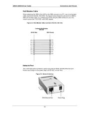
... Network Interface 53 Null-Modem Cable (Lantronix Part No. 500-163) Network Port The unit's back panel contains a power plug and an RJ45 (10/100) Ethernet port. UDS10/UDS100 User Guide Connectons and Pinouts Null-Modem Cable When attaching the DB9 of the UDS to DB9 null-modem cable. Power input... range on a PC, use a null-modem cable (Lantronix Part No. 500-163). The figure below...
... Network Interface 53 Null-Modem Cable (Lantronix Part No. 500-163) Network Port The unit's back panel contains a power plug and an RJ45 (10/100) Ethernet port. UDS10/UDS100 User Guide Connectons and Pinouts Null-Modem Cable When attaching the DB9 of the UDS to DB9 null-modem cable. Power input... range on a PC, use a null-modem cable (Lantronix Part No. 500-163). The figure below...


