Owners Manual
Page 1
DLP Projection TV OWNER'S MANUAL MODELS : RU-44SZ61D RU-52SZ61D Please read this information to your set . Record model number and serial number of the set . Internet Home Page : http://www.lge.com See the label attached on the back cover and quote this manual carefully before operating your dealer when you require service. Retain it for future reference.
DLP Projection TV OWNER'S MANUAL MODELS : RU-44SZ61D RU-52SZ61D Please read this information to your set . Record model number and serial number of the set . Internet Home Page : http://www.lge.com See the label attached on the back cover and quote this manual carefully before operating your dealer when you require service. Retain it for future reference.

Owners Manual
Page 2
...interference when the equipment is encouraged to try to correct the interference by turning the equipment off and on a circuit different from LG Electronics Corporation. The exclamation point within the product's enclosure that the cable ground shall be connected to persons. POWER CORD POLARIZATION: ...modify this product in accordance with the limits for help. However, there is connected. • Consult the dealer or an experienced radio/TV technician for a Class B digital device, pursuant to comply with the instruction manual, may be determined by one or more of important...
...interference when the equipment is encouraged to try to correct the interference by turning the equipment off and on a circuit different from LG Electronics Corporation. The exclamation point within the product's enclosure that the cable ground shall be connected to persons. POWER CORD POLARIZATION: ...modify this product in accordance with the limits for help. However, there is connected. • Consult the dealer or an experienced radio/TV technician for a Class B digital device, pursuant to comply with the instruction manual, may be determined by one or more of important...

Owners Manual
Page 5
...) Operation 27 POP (Picture-out-of Contents Safety Warnings 2 Important Safety Instructions 3-4 Function Status Indicators 6 Step 1. Hook Up TV Rear Connections Panel 7 Front Connections Panel 8 ANT/Cable Service Hookup 9 Cable Box Connections 10 VCR Connections 11 DVD Player 12 RGB/DVI... 2. Miscellaneous Programming the Remote 47 Programming Codes 48-51 Maintenance 52-53 Troubleshooting 54-55 Glossary 56-57 Product Specifications 58 Warranty 59-60 Setup Checklist Step 1. Adjust and fine-tune TV features and options to change without prior notice. PAGE 5 Make...
...) Operation 27 POP (Picture-out-of Contents Safety Warnings 2 Important Safety Instructions 3-4 Function Status Indicators 6 Step 1. Hook Up TV Rear Connections Panel 7 Front Connections Panel 8 ANT/Cable Service Hookup 9 Cable Box Connections 10 VCR Connections 11 DVD Player 12 RGB/DVI... 2. Miscellaneous Programming the Remote 47 Programming Codes 48-51 Maintenance 52-53 Troubleshooting 54-55 Glossary 56-57 Product Specifications 58 Warranty 59-60 Setup Checklist Step 1. Adjust and fine-tune TV features and options to change without prior notice. PAGE 5 Make...

Owners Manual
Page 6
...flashing) Green (flashing) Orange Red Red (flashing) Power cord is overheating. Projection lamp is in standby mode. Contact an authorized service center. The projection TV shut down , check the cooling fan. The projection TV is not connected. Function Status Indicators Lamp indicator, operation indicator, and temperature ... of its life and needs to overheating. Power Cord is connected, TV is reaching the end of the DLP projection TV. On Preparing operation in standby mode. There is not closed. The projection TV shut down due to be replaced with the lamp or around it....
...flashing) Green (flashing) Orange Red Red (flashing) Power cord is overheating. Projection lamp is in standby mode. Contact an authorized service center. The projection TV shut down , check the cooling fan. The projection TV is not connected. Function Status Indicators Lamp indicator, operation indicator, and temperature ... of its life and needs to overheating. Power Cord is connected, TV is reaching the end of the DLP projection TV. On Preparing operation in standby mode. There is not closed. The projection TV shut down due to be replaced with the lamp or around it....
Owners Manual
Page 7
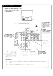
... on the back of equipment. Monitor Out Connects to external Dolby Digital Center "preamp output." Audio Center Mode In Connect to a second TV or Monitor. Picture and sound traveling through your television screen. Video 1 or 2 Connects the video signals from a PC source or HD...-STB Satellite system. PAGE 7 Rear Connections Panel Connecting cables and external equipment to your surround sound system. PC and HD-STB Input Used to your TV. ANT IN +75 Ω C A L I B R A T I O N PC/DTV (XGA /480p /...
... on the back of equipment. Monitor Out Connects to external Dolby Digital Center "preamp output." Audio Center Mode In Connect to a second TV or Monitor. Picture and sound traveling through your television screen. Video 1 or 2 Connects the video signals from a PC source or HD...-STB Satellite system. PAGE 7 Rear Connections Panel Connecting cables and external equipment to your surround sound system. PC and HD-STB Input Used to your TV. ANT IN +75 Ω C A L I B R A T I O N PC/DTV (XGA /480p /...
Owners Manual
Page 8
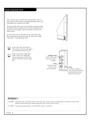
... four jacks on the left front side behind the screen on your projection TV that make sure to change the picture settings with the EZ Picture option in the Main Input menu. They will be connected to those found on the rear jackpack, may be named "Front Video" in the Video menu (see...
... four jacks on the left front side behind the screen on your projection TV that make sure to change the picture settings with the EZ Picture option in the Main Input menu. They will be connected to those found on the rear jackpack, may be named "Front Video" in the Video menu (see...

Owners Manual
Page 9
... have your RF signal through an antenna that is recommended to prevent interference. We recommend using a 75 ohm cable for Ant/Cable connection(s). PAGE 9 Cable TV Wall Jack Panel Antenna RF Coaxial Wire (75 ohm) RF Coaxial Wire (75 ohm) ANT IN +75 Ω S-VIDEO MONITOR VIDEO VIDEO OUT INPUT 2 INPUT... a channel search with two small prongs, you receive your Antenna professionally adjusted. ANT / Cable Service Hookup 1 Connect an antenna and/or cable service to your TV as shown. 2 Turn to page 22 to 75 ohm adapter.
... have your RF signal through an antenna that is recommended to prevent interference. We recommend using a 75 ohm cable for Ant/Cable connection(s). PAGE 9 Cable TV Wall Jack Panel Antenna RF Coaxial Wire (75 ohm) RF Coaxial Wire (75 ohm) ANT IN +75 Ω S-VIDEO MONITOR VIDEO VIDEO OUT INPUT 2 INPUT... a channel search with two small prongs, you receive your Antenna professionally adjusted. ANT / Cable Service Hookup 1 Connect an antenna and/or cable service to your TV as shown. 2 Turn to page 22 to 75 ohm adapter.

Owners Manual
Page 10
... S-VIDEO MONITOR VIDEO VIDEO OUT INPUT 2 INPUT 1 VIDEO MONO (L) AUDIO (R) If you're using a cable box, leave the TV on the back of your cable box, and connect them following the instructions provided with any other equipment you may want to hook up. Or ... cable box to the Antenna jack on the back of your cable box. Cable Box Connections 1 Locate the output jack on the back of your TV. PAGE 10 This can be combined with your equipment. Connect this to change channels.
... S-VIDEO MONITOR VIDEO VIDEO OUT INPUT 2 INPUT 1 VIDEO MONO (L) AUDIO (R) If you're using a cable box, leave the TV on the back of your cable box, and connect them following the instructions provided with any other equipment you may want to hook up. Or ... cable box to the Antenna jack on the back of your cable box. Cable Box Connections 1 Locate the output jack on the back of your TV. PAGE 10 This can be combined with your equipment. Connect this to change channels.

Owners Manual
Page 11
... the wire that you want to receive your signals on Channel 3 or 4, locate the Out to the Antenna In jack on the back of your TV. Video cables. Or, find the composite video and audio jacks on the back of your VCR, and connect them following the instructions provided with... or the S-Video cables to RF out jack on the back of your VCR. PAGE 11 In the event that runs from the Out to TV jack to TV jack on your VCR. If you connect both the composite and the S- Connect a cable from the VCR to the...
... the wire that you want to receive your signals on Channel 3 or 4, locate the Out to the Antenna In jack on the back of your TV. Video cables. Or, find the composite video and audio jacks on the back of your VCR, and connect them following the instructions provided with... or the S-Video cables to RF out jack on the back of your VCR. PAGE 11 In the event that runs from the Out to TV jack to TV jack on your VCR. If you connect both the composite and the S- Connect a cable from the VCR to the...

Owners Manual
Page 12
lowing the instructions provided with TV C A L I B R A T I O N PC/DTV (XGA /480p /720p /1080i) DVI INPUT COMPONENT INPUT2 INPUT1 Y PB PR (L) AUDIO (R) DTV/DVD INPUT RGB INPUT PC/DTV (XGA /480p /720p /1080i) ... jacks on DVD player Y Pb Pr Y B-Y R-Y Y Cb Cr Y PB PR Mini glossary COMPONENT VIDEO Some video equipment uses three separate lines (Y, PB, PR) to your TV. You may connect either the composite video or the S-Video cables to more precisely reproduce images. Your video equipment manual will explain how this relates...
lowing the instructions provided with TV C A L I B R A T I O N PC/DTV (XGA /480p /720p /1080i) DVI INPUT COMPONENT INPUT2 INPUT1 Y PB PR (L) AUDIO (R) DTV/DVD INPUT RGB INPUT PC/DTV (XGA /480p /720p /1080i) ... jacks on DVD player Y Pb Pr Y B-Y R-Y Y Cb Cr Y PB PR Mini glossary COMPONENT VIDEO Some video equipment uses three separate lines (Y, PB, PR) to your TV. You may connect either the composite video or the S-Video cables to more precisely reproduce images. Your video equipment manual will explain how this relates...
Owners Manual
Page 13
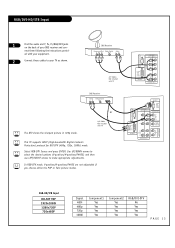
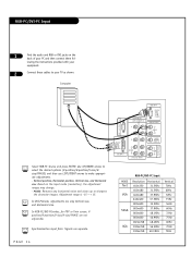
... or The DTV shows the sharpest picture in 720p mode. ed with your equipment. 2 Connect these cables to make appropriate adjustments. A/V Cables Not included with TV C A L I B R A T I O (R) B L E O U T RGB-HD/STB Input HD-SET TOP 1920x1080i 1280x720P 720x480P Signal 480i 480p 720p 1080i ... them following the instructions provid- DBS Receiver Component Out Dolby Digital Audio Y Pb Pr Out L R A/V Cables Not included with TV This TV supports HDCP (High-baudwidth Digital Contents Protection) protocol for DVI-DTV (480p, 720p, 1080i) mode. Use UP/DOWN arrows to select...
... or The DTV shows the sharpest picture in 720p mode. ed with your equipment. 2 Connect these cables to make appropriate adjustments. A/V Cables Not included with TV C A L I B R A T I O (R) B L E O U T RGB-HD/STB Input HD-SET TOP 1920x1080i 1280x720P 720x480P Signal 480i 480p 720p 1080i ... them following the instructions provid- DBS Receiver Component Out Dolby Digital Audio Y Pb Pr Out L R A/V Cables Not included with TV This TV supports HDCP (High-baudwidth Digital Contents Protection) protocol for DVI-DTV (480p, 720p, 1080i) mode. Use UP/DOWN arrows to select...
Owners Manual
Page 14
... with your equipment. 2 Connect these cables to make appropriate adjustments. - Vertical position, Horizontal position, Vertical size, and Horizontal size: Based on the back of your TV as shown. Adjustment range is -15 ~ + 15. Use UP/DOWN arrows to select the desired options (V-position/H-position/V-size/Hsize/PHASE) and then use LEFT...
... with your equipment. 2 Connect these cables to make appropriate adjustments. - Vertical position, Horizontal position, Vertical size, and Horizontal size: Based on the back of your TV as shown. Adjustment range is -15 ~ + 15. Use UP/DOWN arrows to select the desired options (V-position/H-position/V-size/Hsize/PHASE) and then use LEFT...

Owners Manual
Page 15
... Stereo Connections Connect Left/Right Variable Audio Output to an external Audio Amplifier System. 1 Locate both Variable Audio Out jacks on the back of your TV and the Left/Right audio input jacks on the back of your stereo's amplifier. 2 Connect these jacks, making sure that they are connected correctly (red...
... Stereo Connections Connect Left/Right Variable Audio Output to an external Audio Amplifier System. 1 Locate both Variable Audio Out jacks on the back of your TV and the Left/Right audio input jacks on the back of your stereo's amplifier. 2 Connect these jacks, making sure that they are connected correctly (red...

Owners Manual
Page 16
The rear surround sound speakers provide the majority of other sounds, like those from the TV. Any number of other speaker setups are aimed in appropriate directions. Your sub-woofer generates ultra-low frequency sound, for rumbling low-end audio. The TV's sound optional hookup "center mode in," ...makes the dialog sound as though it's coming directly from special effects in movies. You have the option of turning the TV speakers on each side of the speakers, and that they are possible, and some changes may be needed to hear 5.1 channel audio. ...
The rear surround sound speakers provide the majority of other sounds, like those from the TV. Any number of other speaker setups are aimed in appropriate directions. Your sub-woofer generates ultra-low frequency sound, for rumbling low-end audio. The TV's sound optional hookup "center mode in," ...makes the dialog sound as though it's coming directly from special effects in movies. You have the option of turning the TV speakers on each side of the speakers, and that they are possible, and some changes may be needed to hear 5.1 channel audio. ...
Owners Manual
Page 17
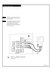
...Out Setup 1 Your TV has a special signal output capability which allows you to the MONITOR OUT Audio/Video jacks locat- ond TV or monitor. 2 Just connect the second TV or monitor to hook up a sec- ed on the back of the second TV or monitor for Monitor Out. Second TV S-Video Video Audio... A/V Cables Not included with TV PAGE 17 ANT IN +75 Ω C A L I B R A T I O...
...Out Setup 1 Your TV has a special signal output capability which allows you to the MONITOR OUT Audio/Video jacks locat- ond TV or monitor. 2 Just connect the second TV or monitor to hook up a sec- ed on the back of the second TV or monitor for Monitor Out. Second TV S-Video Video Audio... A/V Cables Not included with TV PAGE 17 ANT IN +75 Ω C A L I B R A T I O...

Owners Manual
Page 18
... such as a camcorder or game player, is pressed. PIPCHChanges to next lower PIP channel THUMBSTICK Allows you to navigate the on-screen menus and to TV viewing from PIP, POP, or twin picture to the main screen. EXIT Clears all on or off SAP Selects: Mono, Stereo, and SAP. MENU...Selects: DVI-DTV and DVI-PC input sources. SWAP Switches the picture from any button is connected to control external devices. TV VCR CABLE DVD SAT MODE LIGHT POWER TV/VIDEO FRONT DVI COMP1 COMP2 RGB 123 456 789 ENTER 0 FLASHBK MUTE SURF SAP VOL VIDEO CH PIP PIPCH- LIGHT ...
... such as a camcorder or game player, is pressed. PIPCHChanges to next lower PIP channel THUMBSTICK Allows you to navigate the on-screen menus and to TV viewing from PIP, POP, or twin picture to the main screen. EXIT Clears all on or off SAP Selects: Mono, Stereo, and SAP. MENU...Selects: DVI-DTV and DVI-PC input sources. SWAP Switches the picture from any button is connected to control external devices. TV VCR CABLE DVD SAT MODE LIGHT POWER TV/VIDEO FRONT DVI COMP1 COMP2 RGB 123 456 789 ENTER 0 FLASHBK MUTE SURF SAP VOL VIDEO CH PIP PIPCH- LIGHT ...

Owners Manual
Page 19
...PIP INPUT Selects the input source for displaying captioning information if available on mode. ENTER When in EZ Scan memory. PAGE 19 ENTER When in TV Mode COMPONENT 1, 2 Selects component signal sources, such as DVD or HD receiver. CC Selects a closed caption mode for the sub picture.... screen format or aspect ratio. Playing DVDs: Selects movie chapters. RECORD, PAUSE, REW, FFWD, PLAY, STOP Control the functions on your TV or any other programmed equipment on or off, depending on program. VOLUME UP/DOWN Increases/decreases the sound level. NUMBER KEYPAD For direct channel...
...PIP INPUT Selects the input source for displaying captioning information if available on mode. ENTER When in EZ Scan memory. PAGE 19 ENTER When in TV Mode COMPONENT 1, 2 Selects component signal sources, such as DVD or HD receiver. CC Selects a closed caption mode for the sub picture.... screen format or aspect ratio. Playing DVDs: Selects movie chapters. RECORD, PAUSE, REW, FFWD, PLAY, STOP Control the functions on your TV or any other programmed equipment on or off, depending on program. VOLUME UP/DOWN Increases/decreases the sound level. NUMBER KEYPAD For direct channel...

Owners Manual
Page 20
Channel Label If a channel label has been set, then it will appear here. On-Screen Displays This page describes your on remote control. Main Channel Display Displays current channel number. TV 6 AM 03:00 10 Timer 10 min : Mute Appears when sound is active. TV 13 MONO ABC PIP Display This display appears when PIP is muted. PAGE 20 Volume Volume level is displayed while adjusting the sound. Time Appears when pressing the enter button on -screen display and information banner options.
Channel Label If a channel label has been set, then it will appear here. On-Screen Displays This page describes your on remote control. Main Channel Display Displays current channel number. TV 6 AM 03:00 10 Timer 10 min : Mute Appears when sound is active. TV 13 MONO ABC PIP Display This display appears when PIP is muted. PAGE 20 Volume Volume level is displayed while adjusting the sound. Time Appears when pressing the enter button on -screen display and information banner options.

Owners Manual
Page 21
... cold to room temperature before turning it on. - CH 5 6 8 7 See menu pages for TV to adjust to normal room temperature, humidity may form inside TV, wait 3 hours for instructions on the RU-52SZ61D TVs. PAGE 21 The POWER, CHANNEL, TV/VIDEO, and VOLUME buttons work just as ENTER button on your remote control) 4 VOLUME...
... cold to room temperature before turning it on. - CH 5 6 8 7 See menu pages for TV to adjust to normal room temperature, humidity may form inside TV, wait 3 hours for instructions on the RU-52SZ61D TVs. PAGE 21 The POWER, CHANNEL, TV/VIDEO, and VOLUME buttons work just as ENTER button on your remote control) 4 VOLUME...

Owners Manual
Page 22
... sure batteries are prop- back of the remote and install in two AA batteries. Edit Ch. If you have not done so, plug in your TV. Label Main Input Sub Input TIME SPECIAL LOCK F Prev. PIPCH+ SWAP RATIO CC FREEZE PIP INPUT 4 4/6 MENU EXIT PLAY PAUSE STOP RECORD REW FF SKIP... 4 Press the MENU button on the channel list. 1 Refer to pages 7-15 to connect external equipment to your TV to start the EZ Scan channel search. 5/7 TV VCR CABLE DVD SAT MODE LIGHT POWER TV/VIDEO FRONT DVI COMP1 COMP2 RGB 123 456 789 ENTER 0 MUTE FLASHBK SURF SAP VOL VIDEO CH PIP...
... sure batteries are prop- back of the remote and install in two AA batteries. Edit Ch. If you have not done so, plug in your TV. Label Main Input Sub Input TIME SPECIAL LOCK F Prev. PIPCH+ SWAP RATIO CC FREEZE PIP INPUT 4 4/6 MENU EXIT PLAY PAUSE STOP RECORD REW FF SKIP... 4 Press the MENU button on the channel list. 1 Refer to pages 7-15 to connect external equipment to your TV to start the EZ Scan channel search. 5/7 TV VCR CABLE DVD SAT MODE LIGHT POWER TV/VIDEO FRONT DVI COMP1 COMP2 RGB 123 456 789 ENTER 0 MUTE FLASHBK SURF SAP VOL VIDEO CH PIP...


